EP0065250A2 - Bobine de film avec goupille de blocage - Google Patents
Bobine de film avec goupille de blocage Download PDFInfo
- Publication number
- EP0065250A2 EP0065250A2 EP82104031A EP82104031A EP0065250A2 EP 0065250 A2 EP0065250 A2 EP 0065250A2 EP 82104031 A EP82104031 A EP 82104031A EP 82104031 A EP82104031 A EP 82104031A EP 0065250 A2 EP0065250 A2 EP 0065250A2
- Authority
- EP
- European Patent Office
- Prior art keywords
- slot
- film
- clamping plate
- clamping
- spool
- Prior art date
- Legal status (The legal status is an assumption and is not a legal conclusion. Google has not performed a legal analysis and makes no representation as to the accuracy of the status listed.)
- Granted
Links
Images

Classifications
-
- G—PHYSICS
- G03—PHOTOGRAPHY; CINEMATOGRAPHY; ANALOGOUS TECHNIQUES USING WAVES OTHER THAN OPTICAL WAVES; ELECTROGRAPHY; HOLOGRAPHY
- G03B—APPARATUS OR ARRANGEMENTS FOR TAKING PHOTOGRAPHS OR FOR PROJECTING OR VIEWING THEM; APPARATUS OR ARRANGEMENTS EMPLOYING ANALOGOUS TECHNIQUES USING WAVES OTHER THAN OPTICAL WAVES; ACCESSORIES THEREFOR
- G03B17/00—Details of cameras or camera bodies; Accessories therefor
- G03B17/28—Locating light-sensitive material within camera
- G03B17/30—Locating spools or other rotatable holders of coiled film
-
- G—PHYSICS
- G03—PHOTOGRAPHY; CINEMATOGRAPHY; ANALOGOUS TECHNIQUES USING WAVES OTHER THAN OPTICAL WAVES; ELECTROGRAPHY; HOLOGRAPHY
- G03B—APPARATUS OR ARRANGEMENTS FOR TAKING PHOTOGRAPHS OR FOR PROJECTING OR VIEWING THEM; APPARATUS OR ARRANGEMENTS EMPLOYING ANALOGOUS TECHNIQUES USING WAVES OTHER THAN OPTICAL WAVES; ACCESSORIES THEREFOR
- G03B2217/00—Details of cameras or camera bodies; Accessories therefor
- G03B2217/26—Holders for containing light-sensitive material and adapted to be inserted within the camera
- G03B2217/261—Details of spools
Definitions
- the present invention relates to a film spool with retaining pins for fastening a perforated film end in the slot of a spool core of a 35 mm film spool.
- a large number of reel designs are known which are used to wind up various types of tape materials. These reels have the tape attached to the reels for winding in a variety of ways, e.g. by looping, gluing, riveting, clamping or hooking on or in a slot in the coil core.
- the object of the invention is concerned with spools into which the film tape provided with holes is hooked.
- coils are known from DE-PS 1 272 707, which are referred to, for example, as double hook coils. These coils have a slot in the coil spar in which molded hooks and separate guide surfaces are attached. The end of the film with a hole is inserted into this slot, the guide surfaces on both sides of the Hook the film around the hook until the hole in the film snaps into the hook. The guide surfaces prevent the film tape from automatically unhooking from the spool after the hole snaps into the hook due to the film stiffness.
- This known spool shape has the disadvantage that only relatively low tensile forces can be transferred to the film tape materials, which often has the consequence that the film pulls out of the spool and thus becomes unusable or at least can no longer be rewound into the light-proof cartridge.
- US Pat. No. 3,361,380 describes a combination spool-film tape in which two hooks are made in a spool slot and two holes are made in the film bar to improve the holding force.
- This spool is also only of limited suitability for securely attaching the film to the spool and only slightly increases the holding force with which the film can be held in the hook of the spool in the spool slot when a high tensile force acts on the film strip.
- the invention is therefore based on the object to provide a fastening device of the type mentioned with which it is possible in a simple manner to fasten a film end secured against unthreading in a spool in such a way that the fastening withstands a great tensile force and the film end is easy to thread .
- a clamping plate is arranged in the slot of the coil core at an angle to the axially parallel slot surfaces and is pivotably mounted and the clamping plate for hooking the perforated film end with at least one in a groove of the slot movable holding pin is provided.
- This fastening device solves the essential problems of the task in a surprisingly simple manner, namely a hooking of the film end into the slot of the film spool which is secure against unthreading, easy threading which can be carried out mechanically and a high holding force when tensile stress occurs due to the clamping plate which is activated by the retaining pin which engages in a hole in the end of the film and is pivoted into a position in which it clamps the non-perforated part of the end of the film firmly over the entire width with the spool.
- the pull-out strength of the hole in the film end is no longer the only decisive factor, but also the tear resistance of the cross-section of the film end. It was surprising to the person skilled in the art that the tensile force required to pull the film out of the spool was far higher in the spool according to the invention than in the previously used spool Double hook spool and that the end of the film could no longer be threaded out of the holding pin.
- a special embodiment of the fastening device is characterized in that the clamping plate is fastened with at least two hinges to a surface of the slot parallel to the axis of the coil and has a retaining pin and clamping surfaces on the side opposite the hinges, the retaining pin in one, in the Slot machined groove is movable and the clamping surfaces are parallel to the clamping surfaces provided in the slot of the coil.
- this fastening device requires only a small tensile force on the holding pin when it is fastened on one side with hinges in order to be activated and to clamp the width of the film end.
- the end of the filmstrip is pushed against the inclined clamping plate for threading and slips easily between the clamping plate holding pins and the groove in the slot under the holding pins. If the holding pin reaches the elongated hole of the film end, it jumps into the hole, the film end lying straight again due to the elasticity, so that it can no longer be unhooked.
- the end of the film can be threaded into the spool from one side only, so that the spool must be brought into a threading position, which can be almost 360 ° in one direction of rotation for the spool.
- Another advantageous embodiment of the fastening device is characterized in that the clamping plate is provided on the side opposite the hinges with a plurality of retaining pins which are movable in the corresponding grooves machined into the slot.
- the clamping force can be increased, for example, by two holding pins which engage in two holes in the film end.
- the two holding pins center the filmstrip in the winding direction and, after threading, cannot run obliquely onto the spool or be pulled in front of the spool.
- the clamping plate is pulled evenly on two sides against the film lying on the clamping surface of the coil slot and clamps it evenly over the entire width.
- there are also more than two holding pins with a corresponding number of perforations in the film strips can be used, but the number of perforations reduces the clampable area.
- the clamping plate is rotatable about the axis of the coil and has holding pins and clamping surfaces on each of its rotatable longitudinal edges, the holding pins being movable in the grooves machined into the two longitudinal surfaces of the slot and the clamping surfaces of the Clamping plate with the clamping surfaces arranged in the longitudinal surfaces of the slot are parallel.
- This embodiment has the advantage that the film end can be inserted into the bobbin slot from both sides and the bobbin must be brought into a threading position of only 180 °. Because of the smaller lever arm of the clamping plate, the tensile force for activating the clamping force is greater, so that it can be advantageous in this embodiment if the clamping plate has a plurality of retaining pins on each of its rotatable longitudinal sides, which are movable in the grooves machined into the slots.
- the clamping plate can be manufactured separately, but is advantageously injected into the slot by the manufacturer of the coil, the clamping plate being rotatably fastened with torsion bars. To be a good one To maintain the rotatability of the clamping plate, the torsion bars can protrude into a recess in the clamping plate.
- the angle of attack of the clamping plate to the axially parallel surfaces of the slot depends on the design of the hinges or the torsion axes of the clamping plate and can be 5 ° to 45 °. In a preferred embodiment, the angle is 10 ° to 20 °.
- the film spool is provided with at least one mark on a part lying outside the cassette, which indicates the position of the threading slot.
- the coil with the fastening device described can be produced very economically from plastic as a molded part, the clamping plate being sprayed together with the fastening in the slot with the coil.
- the function of the fastening device is safe, so that the coil can be used several times without any interference.
- This security of the fastening device is achieved in that the clamping force for clamping the film end in the spool slot is only activated by pulling on the film and increases disproportionately with increasing pulling force. This process can be repeated any number of times, even if the clamping force has loosened, it is reactivated when the train is pulled again.
- a film spool 1 which consists in the usual manner of a spool core 2 with two flanges and on one side has a spool head which protrudes from the cartridge in a finished film.
- a film strip 3 is wound onto the spool 1, the end 4 of which is attached to the spool in order to be able to wind the film strip 3 back onto the spool in the light-proof cartridge after exposure in a camera.
- a clamping plate 7 is movably attached with at least two hinges or torsion bars 6.
- the clamping plate 7 carries on the movable side opposite the hinges 6 a holding pin 8 which is movable in a groove 9 of the coil slot 5 and clamping surfaces 11 '.
- Fig. 2 shows a section through the coil 1 of Fig. 1 along the line AB.
- the sectional view shows the cut coil core 2 and the clamping plate 7 fastened to it with hinges 6.
- the clamping plate 7 is arranged at an angle ⁇ perpendicular to the parallel surfaces of the slot 5 in the coil spar 2.
- the angle Z is about 25 ° here, but can also be chosen larger or smaller, for example, 6 5 ° to 10 ° for stable hinges or 6 10 ° to 30 ° for lighter hinges.
- the film strip 3 is pushed with its end 4 for threading against the clamping plate 7, bends the clamping plate 7 somewhat in the direction of threading and slips between the holding pin 8 and the groove 9, the film end 4 being deformed in a wave shape.
- an elongated hole 10 is punched (Fig. 6). As soon as the holding pin 8 passes through the elongated hole 10, it jumps into the elongated hole 10, the elastic film end 4 lying straight again and no longer being able to be threaded out without additional aids. The threading process is thus ended and the film end 4 is hooked in the spool 1.
- the elongated hole 10 bears against the holding pin 8 and transmits the tensile force to the latter.
- the clamping surface 11 'of the clamping plate 7 is pressed onto the surfaces of the film end 4 next to the elongated hole 10 and clamps the film strip end 4 against the clamping surfaces 11 of the slot 5.
- the clamping force activated in this way increases disproportionately with increasing tensile force, so that tearing out the slot 10 does not take place, but a separation of the film end from the spool can only be done by tearing the cross section of the film band.
- the holding force of a double hook spool described at the outset is between 3.5 and 5 Kp.
- the values vary depending on the tear and tear resistance of the film material used.
- the ISO standard requires one
- the tensile strength of the film end section is between 11 and 16 Kp for the usual types of film.
- the holding forces of the described fastening device are between 7 and 11 Kp and are therefore twice the known double hook spool and are far above that of the ISO standard of 4 Kp minimum holding force.
- FIG. 3 An equally advantageous embodiment of the fastening device is shown in FIG. 3.
- a clamping plate 7 is rotatably attached to two torsion bars 12 and can be moved about the axis of the coil 1.
- the clamping plate is provided on the two outer edges with a holding pin 8 and clamping surfaces 11 '.
- the holding pins 8 are freely rotatable in the grooves 9, which are incorporated in the slot 5 of the spool 2.
- FIG. 4 shows a sectional view along the line CD of FIG. 3.
- the clamping plate 7 is arranged at an angle in the coil slot 5 and is rotatably mounted on both sides about the coil axis 12.
- the film end 4 of the film strip 3 can advantageously be inserted into the coil slot 5 from both sides, deforms here and jumps into the holding pin 8, after which it lies flat again.
- the film end 4 is clamped between the clamping plate 7 and the clamping surface 11 'and is subjected to tensile strength. Because of the shorter
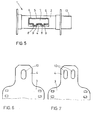
- FIG. 5 shows an embodiment of the fastening device in the slot 5 of the coil 1, in which the clamping plate 7 of FIG. 1 has been modified in that two holding pins 8 have been arranged instead of one holding pin 8.
- the holding pins 8 are freely movable in grooves 9 which are incorporated in the slot 5.
- the film end 4 is provided with two elongated holes 10 (FIG. 7) and, when it is threaded into the bobbin slot 5, it curls twice between the holding pins 8 and the grooves 9 until the holding pins 8 jump into the elongated holes 10 and the film end 4 glows .
- This embodiment has the advantage that the clamping plate is activated in parallel at two points at the same time, whereby the tensile force for activation is transmitted more evenly from the film 3 to the clamping plate 7.
- more than two retaining pins 8 can also be attached to the clamping plate 7, which are freely movable in a corresponding number of grooves 9 and work together with film ends 4 which have a corresponding number of elongated holes 10 (not shown).
- FIG. 5 The arrangement of a plurality of holding pins 8 shown in FIG. 5 can also be used in the embodiment of the fastening device according to FIGS. 3 and 4, the clamping plate 7 then being provided with a plurality of holding pins 8 on both longitudinal edges.
- FIGS. 6 and 7 show the film strips 3 with the elongated holes 10 in the film ends 4.
- round holes can also be used, but these do not penetrate the holding pins as well.
- the elongated holes 10 are kept as narrow as possible in order to keep the cross section of the film end 4 as large as possible and to increase the tear resistance.
- the spool is provided on a part that lies outside the light-proof cassette with a mark 13, which can consist of a flattening, notch or an attached knob and which is arranged so that the position of the threading slot 5 can be felt or felt even outside the closed cassette.
- a mark 13 which can consist of a flattening, notch or an attached knob and which is arranged so that the position of the threading slot 5 can be felt or felt even outside the closed cassette.
- the spool 1 is rotated until the mark 13 reaches a certain position which is favorable for threading and then completed the threading process.
- the coil 1 according to FIG. 1 (5) has an identifier 13 for this purpose and must be rotated by a maximum of almost 360 °, while the coil 1 according to FIG. 3 can have two opposite identifiers 13 or is positioned over the key driver and so only by a maximum must be turned almost 180 ° to reach the threading position.
Landscapes
- Physics & Mathematics (AREA)
- General Physics & Mathematics (AREA)
- Storage Of Web-Like Or Filamentary Materials (AREA)
- Details Of Cameras Including Film Mechanisms (AREA)
Applications Claiming Priority (2)
| Application Number | Priority Date | Filing Date | Title |
|---|---|---|---|
| DE19813119936 DE3119936A1 (de) | 1981-05-19 | 1981-05-19 | Filmspule mit haltezapfen |
| DE3119936 | 1981-05-19 |
Publications (3)
| Publication Number | Publication Date |
|---|---|
| EP0065250A2 true EP0065250A2 (fr) | 1982-11-24 |
| EP0065250A3 EP0065250A3 (en) | 1984-06-13 |
| EP0065250B1 EP0065250B1 (fr) | 1986-08-13 |
Family
ID=6132708
Family Applications (1)
| Application Number | Title | Priority Date | Filing Date |
|---|---|---|---|
| EP82104031A Expired EP0065250B1 (fr) | 1981-05-19 | 1982-05-10 | Bobine de film avec goupille de blocage |
Country Status (3)
| Country | Link |
|---|---|
| EP (1) | EP0065250B1 (fr) |
| JP (1) | JPS57196218A (fr) |
| DE (2) | DE3119936A1 (fr) |
Cited By (1)
| Publication number | Priority date | Publication date | Assignee | Title |
|---|---|---|---|---|
| EP0077972A1 (fr) * | 1981-10-24 | 1983-05-04 | Agfa-Gevaert AG | Bobine à serrer pourvue d'une dent d'attache |
Families Citing this family (1)
| Publication number | Priority date | Publication date | Assignee | Title |
|---|---|---|---|---|
| EP2365013A1 (fr) | 2010-03-12 | 2011-09-14 | Rhein Chemie Rheinau GmbH | Nouvelles masses de coulée de polyuréthane résistant aux intempéries, un procédé de fabrication et d'utilisation de celles-ci |
Family Cites Families (4)
| Publication number | Priority date | Publication date | Assignee | Title |
|---|---|---|---|---|
| US2477010A (en) * | 1946-12-21 | 1949-07-26 | Du Pont | Spool |
| US2911163A (en) * | 1956-01-24 | 1959-11-03 | Warrick Colin | Spools for photographic film and the like |
| US3361380A (en) * | 1966-01-25 | 1968-01-02 | Fuji Photo Film Co Ltd | Spool for photographic film |
| CH479084A (de) * | 1967-04-13 | 1969-09-30 | Agfa Gevaert Ag | Filmspule mit zugehöriger Filmpatrone insbesondere für Kleinbildfilme, zum Befestigen des Filmendes an der Spule innerhalb der Patrone |
-
1981
- 1981-05-19 DE DE19813119936 patent/DE3119936A1/de not_active Withdrawn
-
1982
- 1982-05-10 DE DE8282104031T patent/DE3272545D1/de not_active Expired
- 1982-05-10 EP EP82104031A patent/EP0065250B1/fr not_active Expired
- 1982-05-18 JP JP57082557A patent/JPS57196218A/ja active Pending
Cited By (1)
| Publication number | Priority date | Publication date | Assignee | Title |
|---|---|---|---|---|
| EP0077972A1 (fr) * | 1981-10-24 | 1983-05-04 | Agfa-Gevaert AG | Bobine à serrer pourvue d'une dent d'attache |
Also Published As
| Publication number | Publication date |
|---|---|
| DE3272545D1 (en) | 1986-09-18 |
| EP0065250B1 (fr) | 1986-08-13 |
| JPS57196218A (en) | 1982-12-02 |
| DE3119936A1 (de) | 1982-12-16 |
| EP0065250A3 (en) | 1984-06-13 |
Similar Documents
| Publication | Publication Date | Title |
|---|---|---|
| DE3214615A1 (de) | Kruemmungssteuerungsanordnung fuer ein endoskop | |
| DE2854194A1 (de) | Selbstspannende spule, insbesondere kabeltrommel | |
| DE2348994A1 (de) | Kleinkassette fuer ein magnetband | |
| EP0045428B1 (fr) | Crochet et bobine autopreneuse pour l'enroulement et le déroulement rotatifs | |
| DE8131086U1 (de) | Doppelhakenspule | |
| DE2212103A1 (de) | Vornchtung zum selbsttätigen Auf und Abwickeln von streifenförmigem Material fur Vorfuhrgerate, insbesondere Laufbild Projektoren und Tonbandgerate | |
| DE2945949A1 (de) | Rollo | |
| EP0077972B1 (fr) | Bobine à serrer pourvue d'une dent d'attache | |
| EP0065250B1 (fr) | Bobine de film avec goupille de blocage | |
| DE69617756T2 (de) | Vorrichtung zum blockieren des schlussfadens beim trennen zur zusammenarbeit mitschlussfadenmess-und liefervorrichtungen | |
| DE2429582C3 (de) | Bandkassette | |
| DE2928916C3 (de) | Einrichtung zum Befestigen des Magnetbandes an den Spulen in einer Magnetbandkassette | |
| CH646266A5 (de) | Magnetbandkassette. | |
| DE2326855A1 (de) | Bandabschneidvorrichtung | |
| DE2321782A1 (de) | Kassetten-verriegelungsmechanismus fuer tonbandgeraete | |
| EP0462660B1 (fr) | Appareil à bande magnétique | |
| DE2803758A1 (de) | Kassette fuer rollfilme mit einziehsperre fuer das filmende | |
| DE2444106A1 (de) | Filmspule fuer fotografischen rollfilm | |
| DE803576C (de) | Filmspule mit Friktion | |
| DE966436C (de) | Vorrichtung zum Befestigen von Aufzeichnungstraegern, z. B. Filmbaendern, am Kern vonSpulen | |
| DE2740637C2 (de) | Verfahren und Vorrichtung zum Wickeln von Schraubenfedern mit Vorspannung | |
| DE1963940C3 (de) | Filmspule für Kameras | |
| AT236789B (de) | Filmprojektor | |
| DE2555561C3 (de) | Bremsvorrichtung für die Filmabwickelspule einer Kamera | |
| DE800938C (de) | Kleinbildkamera |
Legal Events
| Date | Code | Title | Description |
|---|---|---|---|
| PUAI | Public reference made under article 153(3) epc to a published international application that has entered the european phase |
Free format text: ORIGINAL CODE: 0009012 |
|
| 17P | Request for examination filed |
Effective date: 19820510 |
|
| AK | Designated contracting states |
Designated state(s): DE FR GB |
|
| PUAL | Search report despatched |
Free format text: ORIGINAL CODE: 0009013 |
|
| AK | Designated contracting states |
Designated state(s): DE FR GB |
|
| GRAA | (expected) grant |
Free format text: ORIGINAL CODE: 0009210 |
|
| AK | Designated contracting states |
Kind code of ref document: B1 Designated state(s): DE FR GB |
|
| REF | Corresponds to: |
Ref document number: 3272545 Country of ref document: DE Date of ref document: 19860918 |
|
| ET | Fr: translation filed | ||
| RAP2 | Party data changed (patent owner data changed or rights of a patent transferred) |
Owner name: AGFA-GEVAERT AG |
|
| PLBE | No opposition filed within time limit |
Free format text: ORIGINAL CODE: 0009261 |
|
| STAA | Information on the status of an ep patent application or granted ep patent |
Free format text: STATUS: NO OPPOSITION FILED WITHIN TIME LIMIT |
|
| 26N | No opposition filed | ||
| PG25 | Lapsed in a contracting state [announced via postgrant information from national office to epo] |
Ref country code: GB Effective date: 19890510 |
|
| GBPC | Gb: european patent ceased through non-payment of renewal fee | ||
| PG25 | Lapsed in a contracting state [announced via postgrant information from national office to epo] |
Ref country code: FR Free format text: LAPSE BECAUSE OF NON-PAYMENT OF DUE FEES Effective date: 19900131 |
|
| PG25 | Lapsed in a contracting state [announced via postgrant information from national office to epo] |
Ref country code: DE Effective date: 19900201 |
|
| REG | Reference to a national code |
Ref country code: FR Ref legal event code: ST |