EP0065262B1 - Vorrichtung mit einer Leitschiene für Gegenstände, die sich um ein Rohr bewegen - Google Patents
Vorrichtung mit einer Leitschiene für Gegenstände, die sich um ein Rohr bewegen Download PDFInfo
- Publication number
- EP0065262B1 EP0065262B1 EP82104078A EP82104078A EP0065262B1 EP 0065262 B1 EP0065262 B1 EP 0065262B1 EP 82104078 A EP82104078 A EP 82104078A EP 82104078 A EP82104078 A EP 82104078A EP 0065262 B1 EP0065262 B1 EP 0065262B1
- Authority
- EP
- European Patent Office
- Prior art keywords
- guide rail
- holder
- piping
- arm
- probe
- Prior art date
- Legal status (The legal status is an assumption and is not a legal conclusion. Google has not performed a legal analysis and makes no representation as to the accuracy of the status listed.)
- Expired
Links
- 239000000523 sample Substances 0.000 claims description 51
- 230000002093 peripheral effect Effects 0.000 claims description 4
- 210000000078 claw Anatomy 0.000 description 22
- 230000007246 mechanism Effects 0.000 description 21
- 230000008859 change Effects 0.000 description 11
- 238000001514 detection method Methods 0.000 description 7
- 230000009471 action Effects 0.000 description 4
- 239000003638 chemical reducing agent Substances 0.000 description 4
- 230000000694 effects Effects 0.000 description 4
- 238000010276 construction Methods 0.000 description 3
- 230000008878 coupling Effects 0.000 description 3
- 238000010168 coupling process Methods 0.000 description 3
- 238000005859 coupling reaction Methods 0.000 description 3
- 230000003247 decreasing effect Effects 0.000 description 3
- 230000009467 reduction Effects 0.000 description 3
- 230000005540 biological transmission Effects 0.000 description 2
- 238000007689 inspection Methods 0.000 description 2
- 230000004048 modification Effects 0.000 description 2
- 238000012986 modification Methods 0.000 description 2
- 230000002441 reversible effect Effects 0.000 description 2
- 230000004323 axial length Effects 0.000 description 1
- 230000000295 complement effect Effects 0.000 description 1
- 230000003292 diminished effect Effects 0.000 description 1
- 230000003467 diminishing effect Effects 0.000 description 1
- 230000005484 gravity Effects 0.000 description 1
- 230000006872 improvement Effects 0.000 description 1
- 238000000034 method Methods 0.000 description 1
- 230000000737 periodic effect Effects 0.000 description 1
- 230000002285 radioactive effect Effects 0.000 description 1
- 230000004044 response Effects 0.000 description 1
- 230000000717 retained effect Effects 0.000 description 1
- 238000005096 rolling process Methods 0.000 description 1
Images





Classifications
-
- G—PHYSICS
- G01—MEASURING; TESTING
- G01N—INVESTIGATING OR ANALYSING MATERIALS BY DETERMINING THEIR CHEMICAL OR PHYSICAL PROPERTIES
- G01N29/00—Investigating or analysing materials by the use of ultrasonic, sonic or infrasonic waves; Visualisation of the interior of objects by transmitting ultrasonic or sonic waves through the object
- G01N29/22—Details, e.g. general constructional or apparatus details
- G01N29/26—Arrangements for orientation or scanning by relative movement of the head and the sensor
- G01N29/265—Arrangements for orientation or scanning by relative movement of the head and the sensor by moving the sensor relative to a stationary material
Definitions
- the present invention relates to a guide rail apparatus of the kind referred to in the precharacterizing portions of claims 1 and 4.
- Such guide rail apparatus are known from US-A-3 921 440 and DE-A-2 930 628, respectively.
- the guide rail apparatus of the invention can be applied, for example, to the guiding of running type ultrasonic flaw detector for examining weld parts of piping in nuclear power station.
- Non-destructive inspection particularly the ultrasonic flaw detection
- the ultrasonic flaw detection has been made mainly through manual work.
- the driving apparatus for driving the scanning probe is guided along a guide rail apparatus in the form of links previously arranged around the piping, in order to obtain correct information concerning the position of the probe.
- the guide rail apparatus heretofore proposed are designed for straight portions of the piping and, hence, can be applied only to several tens of percents of the whole portion of the piping, Namely, the weld parts of piping in nuclear power station are found mainly in the following portions; the portion where the axis is flexed, portion where the diameter of the pipe is varied, portion where an equipment is connected, and the portion where the pipe is branched or dispersed. In every part of a piping system there are portions where the axis is flexed or bent. Therefore, the rate of application of the automatic scanning system can be increased considerably by designing the guide rail apparatus for application to complicated portions of piping such as elbow.
- a split-ring type guide rail 1 embraces the straight portion 2 of a piping in such a manner that the circumferential line of the guide rail 1 extends in parallel with the weld line 3.
- a driving unit 4 is mounted on the guide rail 1 by engaging rollers 5 to be able to run along the guide rail 1 in the circumferential direction so that the probe 6 scans the pipe around the weld line 3 in both of circumferential and axial directions.
- the probe 6 is resiliently pressed against the surface to be examined by a holder 7 through a spring 8.
- FIG. 2 shows another conventional apparatus in which a guide rail 1 is attached to the outer surface of an elbow 11 for permitting the probe 6 to scan the portion in the vicinity of the weld line 3, wherein the axial length is varied in accordance with the movement of the guide rail 1.
- this known apparatus it is necessary to vary the angle between the guide rail 1 and the arm 9 around the axis 14 of rotation and also to vary the angle between the examined surface and the arm 9. For these reasons, various difficulties are caused such as complicated manipulation, uneasy handling and troublesome processing of signals for detecting the position of the probe 6.
- a driving unit 203 is attached to a track 207 secured to a straight pipe 201 by openable rollers 206.
- the driving unit 203 incorporates a motor the power of which is transmitted to a pinion 205 meshing with racks 208 formed on the track 207 so that the driving unit as a whole moves in the circumferential direction.
- another motor drives a screw (not shown) extending in parallel with an arm 204 so that a holder 211, incorporating a nut meshing with the screw, is moved accompanying the arm 204.
- the scanning probe 202 for transmitting/ receiving ultrasonic wave is made to run in both of circumferential and axial directions to thereby automatically conduct the examination.
- the scanning instruction is given from a remote plate by means of a cable.
- This apparatus cannot be applied to the pipe of complicated form such as an elbow 210, because the length of the arm 204 is too large and abuts the pipe surface and because the probe 202 cannot delicately follow the examined surface of complicated form.
- this apparatus also fails to improve the rate of application of automatic ultrasonic flaw detection to the inspection of piping.
- US-A-3 921 440 and DE-A-2 930 628 disclose ultrasonic pipe testing systems in which the scanning can be conducted with the probe moving in parallel with or perpendicularly to the weld line of the piping, while keeping the probe in contact with the piping, provided that the piping is straight.
- the primary object of the invention is to provide a guide rail apparatus for guiding an object running around piping, capable of securing a moving object such as a probe driving unit or the like even to pipes having no straight portion to widen the capability of attaching of the running body while improving the running stability and simplifying the signal processing and maneuverability, and further to provide a small-sized and light-weight probe driving unit capable of running smoothly and automatically following up the surface of the examination object having a complicated form such as an elbow pipe.
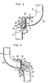
- a guide rail apparatus attached to a pair of continuous elbows bent in opposite directions, includes a guide rail designated 34 secured along a weld line 31 and fixed to the elbow by means of a holder 35 through a rib 36.
- the holder 35 is adapted to clamp the elbow by means of movable claws operatively related to movable claws on the guide rail 34 through a flexible shaft 43, such that the claws are pressed against the surface of the elbow by a manipulation of a handle 44.
- the length of the rib 36 is adjustable by means of a turn buckle which includes left and right handed threaded portions 38 and a nut so that the distance between the weld line 31 and the guide rail 34 is preadjustable.
- the openable ends of the holder 35 and the guide rail 34 are disposed at the same side of the elbow.
- a driving unit 32 is attached to the guide rail 34 and is moved along the latter to make a probe 33 thereon scan the elbow in the circumferential direction. At the same time, the probe 33 is moved along one arm 51 to scan the elbow also in the axial direction. As shown in Fig.
- a rear-side rib 49 is detachably connected to the holder 48 of the guide rail 34 by means of a hook 47.
- the holder 35 is formed as a split-type ring-like member composed of two segments 35a, 35b, hinged to each other by a hinge 39 and the two segments 35a, 35b are swingable around the hinge 39 to open and close the holder 35 for mounting on and removal from the elbow by the manipulation of a handle 40 which is rotatable around the axis of a rotary shaft 62.
- a handle 40 As the handle 40 is rotated to one position as shown by solid line, a deformed pin 66 (Fig. 6B), integral with the shaft 62, comes into an opening in a pin 65 to thereby lock the ends of the holder segments 35a, 35b.
- the handle 40 For opening the holder 35, the handle 40 is rotated to the position shown in phantom line (Figs. 5, 6A) so that the deformed pin 66 is rotated 180° to come out of engagement with the pin 65 thereby enabling the pin 66 to be withdrawn.
- the handle 40 By so doing, it is possible to swing the holder segments 35a, 35b away from each other to form the opening for mounting on and removal of the holder from the pipe.
- hinge 39 is adapted to open around a pin 73 and the opening angle thereof is limited by a wire fixed to the stationary shaft 71.
- the clamp mechanism has movable claws 60a, 60b and 60c (Fig. 5) adapted to be projected and retracted through rotation of flexible shafts 61a, 61b and 61c (Fig. 5) as the ratchet type handle 44 is rotated around the axis of the rotary shaft 63, thereby to clamp and unclamp the surface to be examined.
- the gear 81 is rotated only in one direction through the ratchet 80 so that the shaft 85 is rotated to rotate the flexible shafts 61 a, 61 b, 61c (Fig. 5) in the holder 35 to thereby project or retract the movable claws 60a, 60b, 60c.
- torque is transmitted from the shaft 85 to the flexible shaft 43 connected to the guide rail 34 to simultaneously project or retract the movable 100a, 100b, 100c (Fig. 11) claws adjacent to the guide rail 34.
- the handle 82 is swung in the reverse direction to change the position at which the pin 83 presses the ratchet 80 to thereby press another ratchet 80b to the gear 81 thereby enabling the shaft 85 to be turned in reverse.
- the transmission mechanism in the holder 35 includes, as shown in Fig. 9, a bevel gear 88 driven by the shaft 85, with the bevel gear 88 driving shafts 86a and 86b through bevel gears 87a and 87b. Furthermore, the rotation of the shaft 85 is transmitted to the flexible shafts 61a, 61 connected to the couplings 90a, 90b, so that rotation is imparted to the mechanism for projecting and retracting the movable claws 60a, 60b and 60c shown in Fig. 5.
- a flexible shaft 61c is adapted to rotate a screw 91 through a coupling 90c, to thereby move a nut 92 to change the angle of the arm 93 connected to the nut 92. Consequently, the movable claw 60c connected to the arm 93 is projected and retracted.
- the movable claw 60c is provided with a flexible joint 94 which can be deformed freely in accordance with the form of the surface to be examined to thereby optimumly orientate a claw portion 95 which is provided with an anti-slip rubber portion 96.
- the mechanisms for driving the other movable claws 60a, 60b are materially identical to that for the movable claw 60c.
- the guide rail 34 is formed as a split-type ring member consisting of two segments 35a, 35b is openable around a hinge 52 as in the case of the holder 35. Clamping and unclamping action of the guide rail 34 is accomplished by manipulation of a handle 41 by the same mechanism as that shown in Fig. 6.
- the hinge 52 is different from the hinge 39 of that holder 35 as shown in Figs. 12A and 12B, semicircular guide rail segments 35a and 35b are connected to each other by the hinge 52 to form a circle.
- the guide rail segments 35a, 35b are swung around the hinge 52 along the slide surfaces 107 and 108 to clamp and unclamp the object to be examined.
- the pin 105 fixed to the guide rail segment 35b, slides along the hole 106 so that the angle of the sliding movement is limited by the length of the hole 106.
- the rib 49 is detached from the holder 48 after removing the driving unit 32 from the guide rail 34, and the universal joint is rotated to the starting position and fixed at a position between the leaf springs 50.
- the handles 40 and 41 are manipulated to open the holder 35 and the guide rail 34 by swinging respective segments 35a, 35b around their hinges 39 and 52.
- the holder 35 and the guide rail 34 are opened by swinging their segments 35a, 35b around respective hinges 39, 52 and are secured to the external surface of the elbow pipe 30 and then the handles 40 and 41 are manipulated to close the segments 35a, 35b into a ring-like form.
- the hook 47 on the end of the rib 49 is retained by the holder 48.
- the length of the rib 49 is beforehand adjusted optimumly by means of a turn buckle consisting of a threaded portion 53 and nut 45.
- the handle 44 shown in Fig. 3 is manipulated to drive the movable claws 60a, 60b, 60c and 100a, 100b, 100c of the holder 35 and the guide rail 34 to thereby clamp the elbow pipe 30.
- the driving unit 32 is mounted on the guide rail 34.
- Fig. 13 shows the detail of the rotary shaft 101.
- the torque transmitted from the holder 34 through the flexible shaft 43 is then transmitted to a screw gear 112 through a shaft 110 and a screw gear 112 thereby to rotate the flexible shaft operatively connected to the movable claw.
- the driving unit 32 is secured to the guide rail 34 by means of rollers 113 on the arms 114.
- the driving power from the rollers 115,118 and motor (not shown) is transmitted to the pinion 116 meshing with the rack 117 so that the driving unit 32 runs along the guide rail 34.
- the driving unit 32 is safely carried by the rollers 113, 115 and 118, and is prevented by the roller 118 from being offset laterally.
- the torque from the holder 34 is transmitted to the shaft 110 and screw gears 111, 112 through the flexible shaft 43.
- the torque of the screws 111 and 112 is transmitted to the couplings 120a, 120b and the flexible shafts 102a, 102b and drives the right and left-hand screw similar to that shown in Fig. 10 thereby to project and retract the movable claws 100a, 100b, 100c to clamp and unclamp the object to be examined.
- the movable claw 100b shown in Fig. 11 is secured at a certain inclination due to the curvature of the outer surface of the elbow pipe, in contrast to the other movable claws 100a and 100c.
- the driving unit 32 secured to the outer periphery of the guide rail 34 is held by the rollers 113 connected to the arms 114 and the rollers 115, 118 contacting the outer surface, and is driven by the mutual engagement between the pinion and the rack 117.
- the driving unit 32 since the roller 118 is received by the V-shaped groove formed in the outer surface of the guide rail 34, the driving unit 32 is located in the direction perpendicular to the circumference of the guide rail 34.
- a guide rail apparatus applicable even to pipes having complicated form such as elbows, so that the applicability of the automatic flaw detection or the like is remarkably widened and the rate of adoption of automatic control can be increased as compared with the prior art.
- the guide rail 34 is mounted to extend in parallel with the weld line 31 the movement of the probe 33 achieved by the driving unit 32 can be advantageously simplified. This arrangement, therefore, offers various advantages such as reduction of number of drive shafts in the driving unit 32, simplification of the mechanism and reduction in number of the probes 33. The number of position signals and angle signals is also decreased to facilitate the processing of signals.
- the mounting/removing of the apparatus can be made by a simple operation, the time length required for the manipulation is very much shortened to decrease the exposure to radioactive rays.
- the invention it is possible to achieve remarkable improvement in the aspects of adaptability to piping having complicated form, maneuverability and accuracy of examination.
- the guide rail 34 and the holder 35 are connected to each other by means of an expandable rib 36.
- an expandable rib is not essential and it is possible to use a rigid rib 137 such as shown in Fig. 15.
- the movable claws, 60a, 60b, 60c and 100a, 100b, 100c on both of the holder 35 and the guide rail 34 are driven by the manipulation of a single handle 44 to effect the clamping and unclamping action of both members simultaneously.
- This arrangement is not exclusive. Namely, it is possible to arrange such that the holder 35 and the guide rail 34 are operated independently by respective handles. It is also possible to place a rubber or the like elastic member between the pipe surface and the members mounted on the pipe surface.
- the described construction of the guide rail can be substituted by any other suitable construction.
- each of the holder 35 and the guide rail 34 are divided into two semicircular segments such that the hinge and the opening diametrically oppose to each other, this is not exclusive and the angle of opening may be varied as desired provided that it permits each of the holder 35 and the guide rail 34 clear of the pipe during mounting and removal. In other words, the angular distance between the hinge and the opening may be greater or less than 180° as shown in Fig. 16.
- a holder 143 is secured to the portion near the juncture between the reducer pipe 140 and the valve 142 so that the guide rail 144 can be fixed more securely than the case where the guide rail 144 is disposed at the inclined portion. It is thus possible to secure a driving unit 147 even to such a pipe.
- the guide rail apparatus can be broadly used as guide rail apparatus for various types of automatic apparatus such as automatic welder, industrial robot or the like.
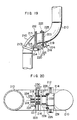
- Fig. 18 shows another embodiment of the invention wherein a driving unit 214 is mounted on a rail 212 secured to a piping 210 consisting of two elbows welded to each other.
- the axial scanning movement of the probe 219 is effected by means of a motor mounted on a truck 216 which moves on an arm 217 through a screw while transmitting the torque of the motor to a screw extending in parallel with the arm 224 to shift a holder 218.
- a mechanism is provided for making the probe 219 move following up the form of the surface of the piping 210 and the angle between the arms 217 and 224 around the shaft 220 is varied around the shaft 220.
- the circumferential scanning by the probe 219 is effected by means of the driving unit 214 which is adapted to move along the outer surface of the track 212 secured by means of a holder 213 through ribs 215.
- the holder 213 is of the same type as that shown in Figs. 3 and 4.
- the embodiment shown in Figs. 18 and 19 is provided with parts, as a hinge, handle and a clamp similar to those shown in Figs. 3 and 4.
- the driving unit 214 has a motor the output torque of which is transmitted to a pinion meshing with a rack on the rail 212 so that the driving unit as a whole runs along the track 212.
- the rollers 221 and 222 provided on the arms 223 are kept in contact with or away from the pipe surface depending on the shape of the latter to vary the angle of the arm 217 and the arm 224. For instance, as the driving unit 214 is moved to the lower part of the rail 212 as shown in Fig. 19, the arms 217 and 224 are lowered around the shaft 220 by the force of gravity, so that the driving unit 214 is held by rollers 222 provided on the ends of the arms 223 extending around the pipe 210.
- the driving unit 214 has a circumferential driving section 231 for the driving in the circumferential direction.
- various angles in the driving unit 214 are changeable.
- the mounting of the driving unit 214 on the rail 212 is made by the mounting removal mechanism 226 basically same as that shown in JP-A-92939/1978. The detail of this mechanism will be described later.
- the mounting/removal mechanism 226 and the motor 228 are projected in the same side as the arm 217.
- the axial driving is made by driving the truck 216 along the arm 217 by rotating a nut meshing with the screw 230 by means of the motor 227.
- the rotation of the motor 207 is transmitted also to a screw 229, so that the holder 218 with the probe 219 is moved along the arm 224. Consequently, the movement of the probe 219 is doubled by the truck 216 and by the holder 218.
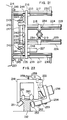
- the axial driving section is mounted on the track 232 which is mounted to freely change the angle between the driving unit 214 and the arms 217,224. At the same time, an arm 223 is secured to the end of the arm 217.
- the torque of the motor 227 is transmitted from a gear 236 to a gear 235 through a speed reducer 248 to thereby drive the nut 233 and, at the same time, a gear 246 is rotated through gears 241, 242, shaft 247 and gears 243, 244 to thereby drive another nut 233. Consequently, the nuts 233 are moved upon engagement with the screws 230 to drive the truck 216 along the arm 217.
- the rotation of the gear 236 is transmitted through a gear 237 to gears 238, 239 and 240. Consequently, two screws 229 are rotated to drive the nut 234 integral with the holder 218. As a result, the speed of movement of the probe 219 is doubled because the probe 219 moves along the arm 224 while the truck 216 moves along the arm 217.
- This axial driving section is secured to the truck 232 and also secured by the holder 245 of the driving unit 214. Namely, the axial driving section is held rotatably by a shaft 220 received by a hole formed in the holder 245.
- the driving unit 214 is held by means of rollers 251, 252 contacting with the inclined portion of the rail 212.
- a ratchet 258 is pressed to disengage the claw on the end of the ratchet 258 from the teeth of the arm 255, so that the arm 254 as a unit with the leaf spring 253 and the holder 262 is swung outwardly to open to thereby permit the removal of the driving unit 214.
- the arm 254 is pressed so that the claw on the end of the ratchet 258 successively move on the teeth of the arm 255 by the action of the spring 259 to thereby press the roller 252 onto the inclined surface of the rail 212.
- the joint surfaces of the arm 254 and the arm 255 are provided with complementary projections and recesses meshing with each other, and the two arms 254 and 255 are fastened in this state to each other by means of a screw 256.
- the length is adjusted in accordance with the change by means of the screw 256 in accordance with the change in the diameter of the rail 212.
- the outer peripheral surface of the rail 212 has a V-shaped groove and flat surfaces. Tow pairs of V-shaped rollers 260 and 261 make rolling contact with this outer peripheral surface to thereby axially locate the driving unit 214.
- the torque of the motor 228 is transmitted from the motor 228 to the pinion 263 through the speed reducer 266, so that the circumferential driving section is moved circumferentially through the mutual engagement between the rack 267 of the rail 212 and the pinion 263.
- Two sets of V-shaped rollers 260 and 261 located at another position serve to adjust the condition of meshing between the pinion 263 and the rack 267.
- a shaft 275 inserted into a groove 272 of a stopper 271 formed on the rotary shaft of the arm 223 is withdrawn from the same by a manipulation of a lever 276 to permit the arm 223 to rotate and, then, the shaft 275 is inserted into another groove 273, so that the arm 223 is fixed at the opening position.
- the closing of the arm 223 is made in the same manner by inserting the shaft 275 into the groove 272.
- the probe 219 is adapted to rotate around the axis of a shaft 305 interconnecting a ring 304 and the probe 219 until the ring 304 comes to interfere the probe 219.
- the probe 219 is connected to the ring 304 by means of a shaft 306 provided on the holder 310, to permit a rotation in the direction which is 90° offset from the direction of the shaft 305.
- a pneumatic cylinder 300 which is secured to the holder 218 through a shaft 302, is adapted to press the probe 219 resiliently against the surface of the piping 210.
- the pneumatic cylinder 300 is supplied with air of a predetermined pressure from air tubes 309, 308 through an air supply port 301. Consequently, as the surface to be examined is varied as in the case of the pipe 210A, the inner cylinder or plunger 307 of the pneumatic cylinder 300 is pressed by the air to resiliently press the probe 219A against the pipe surface following up the curvature of the same. As shown in Fig. 26, the pneumatic cylinder 300 accommodates a plurality of inner sleeves 307 which are housed completely by the pneumatic cylinder 300 when the latter is in a contracted condition.
- the inner sleeve 307 of the smallest diameter and, then, the inner sleeve of diameter next to the smallest and so forth are successively extended by the pressure of air supplied into the pneumatic cylinder 300 through the pneumatic tube 308 and the air supplying port 301 to follow up the change in the condition of the pipe surface.
- the inner sleeves 307 are forced into the pneumatic cylinder 300 in the following cases: namely, where the force is applied solely by the weight of members such as arm 217, arm 224, arm 223 and so forth as shown in Fig.
- the force required for contracting the inner sleeves 307 is increased as the diameter of the inner sleeves 307 becomes greater to increase the reactional force against the contracting force.
- the last described embodiment offers the following advantages.
- the apparatus is adaptable to piping having complicated form, the ratio of automation is very much increased. Namely, it is possible to vary the arm angle and arm length in accordance with the complicated form of the piping, and to control the pressing stroke and the pressing angle following up the change in the condition of the pipe surface.
- the pipe to be examined consists of elbows welded to each other, it is possible not only to effect the scanning following up the form of the pipe but also to effect such an automatic adjustment as to reduce the stroke on the portion of the elbow of small curvature to prevent the interference of the arm end while, on the portion of the elbow having a large curvature, the stroke is increased to a sufficiently large length.
- the running object can be retracted to the original position of the arm 217 and can be pushed forward to the position of the end of the arm 224. Consequently, it is possible to increase the length of the arm or the ratio of the effective stroke to the overall length of the apparatus, which in turn permits a reduction in the length of the apparatus. Furthermore, when there is an obstruction such as valve on the end of the pipe or when the examination is effected on the inward curvature of the elbow-elbow piping, it is possible to select beforehand the length in such a manner as to avoid interference with the arm 224. Thus, the -apparatus of the invention can be used with a large flexibility or adaptability to a large variety of condition around the piping.
- the torque is transmitted simultaneously from a single motor 227 to the nut 233 and the screw 229, it is possible to double the running speed of the running body. If there is any margin in the running speed of running body per revolution of the motor shaft, it is possible to increase the driving torque by reducing the running speed by an amount corresponding to the margin. It is thus possible to obtain either a higher speed or a greater torque depending on the purpose or use.
- the arm is adapted to be extended and retracted in two stages. This however, is not exclusive and it is possible to obtain a four-stage operation by adding the same combination of the motor, nut and the screw and applying an equal voltage to both motors.
- the number of stages of the expandable arm is not limited and can be varied as desired.
- the angle of the expandable arm can be varied as desired, the expandable arm may be used at a fixed angle in the examination of a pipe having a simple configuration such as a straight pipe.
- the expandable arm which is located at each side of the probe in the described embodiment may be provided only at one side of the probe if there is no sufficient room for mounting the arm or when the requirement for the precision of position is not so severe.
- the expandable arm is opened at its one end and cantilevered to reduce the height from the pipe surface, it is possible to connect the ends of two arms of the same stage in some uses.
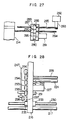
- Fig. 27 shows a modification of the expandable arm and, according to this figure, the torque of the motor 281 is transmitted to gears 287, 288 through a gear 286 to thereby rotate the nuts 290 and 289 meshing with the screws 284 and 285.
- the truck 280 is moved along the screw 284 and, at the same time, the screw 285 is moved, so that the probe attached to the holder 285 on the end of the screw 285 can be moved at a doubled speed for scanning.
- Fig. 28 provides an example of another embodiment for feeding two stages of arm simultaneously. More particularly, in Fig. 28, the torque of the motor 227 can be changed as desired by means of buttons 291, 292 and gears 294 and 295 are switched as desired to drive the screw 229 solely or the nut 233 solely. For instance, in the case where the arm cannot be sufficiently stretched due to the presence of an obstruction, the gear 295 is disengaged to permit the screw 229 solely, so that the arm is not elongated because the truck 216 does not move. In such a case, the probe moves only along the arm 224 and the screw 229.
- the mechanism 226 may be provided in duplicate for each driving section. Namely, the number of the mechanisms 226 may be increased or decreased depending on the uses and the shape and the position of the mechanisms may be selected freely. It is also possible to mount the roller 251 for free adjustment of angle, although it is fixed in the arrangement shown in Fig. 22.
- multi-staged pneumatic cylinder It is also possible to substitute the air relieving grooves in the inner surfaces of multi-staged pneumatic cylinder by valves or the like which automatically regulate or control the pneumatic pressure in the pneumatic cylinder which gradually increases in response to the reactional force from the probe or the like.
- valves or the like which automatically regulate or control the pneumatic pressure in the pneumatic cylinder which gradually increases in response to the reactional force from the probe or the like.
- the described multi-staged pneumatic cylinder can be used as an independent device for automatic flaw detector for other purposes or even to other applications.
Landscapes
- Physics & Mathematics (AREA)
- Health & Medical Sciences (AREA)
- Life Sciences & Earth Sciences (AREA)
- Chemical & Material Sciences (AREA)
- Analytical Chemistry (AREA)
- Biochemistry (AREA)
- General Health & Medical Sciences (AREA)
- General Physics & Mathematics (AREA)
- Immunology (AREA)
- Pathology (AREA)
- Investigating Or Analyzing Materials By The Use Of Ultrasonic Waves (AREA)
Claims (4)
Applications Claiming Priority (4)
| Application Number | Priority Date | Filing Date | Title |
|---|---|---|---|
| JP56070802A JPS57186165A (en) | 1981-05-13 | 1981-05-13 | Guide rail device for guiding body running around piping |
| JP70802/81 | 1981-05-13 | ||
| JP122960/81 | 1981-08-07 | ||
| JP56122960A JPS5824857A (ja) | 1981-08-07 | 1981-08-07 | 超音波探触子の駆動装置 |
Publications (3)
| Publication Number | Publication Date |
|---|---|
| EP0065262A2 EP0065262A2 (de) | 1982-11-24 |
| EP0065262A3 EP0065262A3 (en) | 1985-01-23 |
| EP0065262B1 true EP0065262B1 (de) | 1987-08-12 |
Family
ID=26411935
Family Applications (1)
| Application Number | Title | Priority Date | Filing Date |
|---|---|---|---|
| EP82104078A Expired EP0065262B1 (de) | 1981-05-13 | 1982-05-11 | Vorrichtung mit einer Leitschiene für Gegenstände, die sich um ein Rohr bewegen |
Country Status (3)
| Country | Link |
|---|---|
| US (1) | US4515018A (de) |
| EP (1) | EP0065262B1 (de) |
| DE (1) | DE3276967D1 (de) |
Families Citing this family (10)
| Publication number | Priority date | Publication date | Assignee | Title |
|---|---|---|---|---|
| DE3337635A1 (de) * | 1983-10-15 | 1985-04-25 | M.A.N. Maschinenfabrik Augsburg-Nürnberg AG, 8500 Nürnberg | Manipulator zur pruefung von rohrleitungs-kruemmerrund- und -laengsschweissnaehten in kernkraftanlagen |
| US4586379A (en) * | 1984-09-28 | 1986-05-06 | Virginia Corporation Of Richmond | Ultrasonic pipe inspection system |
| EP0646790B1 (de) * | 1987-09-21 | 2000-05-03 | Hitachi, Ltd. | Verfahren und Gerät zur Detektion der Versprödung von Metallen |
| US6222897B1 (en) * | 1998-02-27 | 2001-04-24 | General Electric Company | Wrist raster scan methods |
| DE10146340A1 (de) * | 2001-09-20 | 2003-04-10 | Eads Deutschland Gmbh | Ultraschall-Prüfvorrichtung und Prüfgerät zur Prüfung von Materialien und Verbindungsbereichen |
| JP4580913B2 (ja) | 2006-08-17 | 2010-11-17 | 株式会社東芝 | ジェットポンプライザの補強装置 |
| CN107917953B (zh) * | 2017-11-03 | 2021-07-02 | 中国石油天然气集团公司 | 一种压裂弯头活动部位检验方法 |
| CN110031551B (zh) * | 2019-05-17 | 2021-09-21 | 中国石油天然气第一建设有限公司 | 一种可双向扫查的自动化接管角焊缝相控阵检测装置 |
| CN114062395B (zh) * | 2021-11-18 | 2024-04-19 | 江苏科技大学 | 一种用于高温管道探伤的α射线无损检测装置 |
| CN114295616B (zh) * | 2022-03-11 | 2022-05-10 | 西南石油大学 | 基于图像识别的套管检测设备 |
Family Cites Families (6)
| Publication number | Priority date | Publication date | Assignee | Title |
|---|---|---|---|---|
| US3921440A (en) * | 1975-01-02 | 1975-11-25 | Air Prod & Chem | Ultrasonic pipe testing system |
| JPS5518987A (en) * | 1978-07-28 | 1980-02-09 | Hitachi Ltd | Ultrasonic flaw detecting drive device |
| JPS5920102B2 (ja) * | 1979-04-09 | 1984-05-10 | 中国電力株式会社 | 超音波探傷装置 |
| SU819706A1 (ru) * | 1979-05-25 | 1981-04-07 | Предприятие П/Я Р-6476 | Сканирующее устройство |
| JPS5619451A (en) * | 1979-07-27 | 1981-02-24 | Sumitomo Metal Ind Ltd | Scanner for ultrasonic flaw detection |
| JPS5952985B2 (ja) * | 1979-09-28 | 1984-12-22 | 中国電力株式会社 | 環状ガイドレ−ル装置 |
-
1982
- 1982-05-11 EP EP82104078A patent/EP0065262B1/de not_active Expired
- 1982-05-11 DE DE8282104078T patent/DE3276967D1/de not_active Expired
- 1982-05-11 US US06/377,159 patent/US4515018A/en not_active Expired - Fee Related
Also Published As
| Publication number | Publication date |
|---|---|
| EP0065262A2 (de) | 1982-11-24 |
| EP0065262A3 (en) | 1985-01-23 |
| US4515018A (en) | 1985-05-07 |
| DE3276967D1 (en) | 1987-09-17 |
Similar Documents
| Publication | Publication Date | Title |
|---|---|---|
| US4515018A (en) | Guide rail apparatus for an object running around piping | |
| US4084453A (en) | Power tongs | |
| US11364529B2 (en) | Variable-diameter full-support mandrel structure with slider-type cross section for preventing reverse rotation of ratchet wheel | |
| US4404876A (en) | Power tongs | |
| US4131018A (en) | Elbow or bent tube manipulator, especially for ultrasonic testing in nuclear reactor installation | |
| US4586379A (en) | Ultrasonic pipe inspection system | |
| JPS5920102B2 (ja) | 超音波探傷装置 | |
| US4389894A (en) | Cylindrical guide rail for detector | |
| GB1372327A (en) | Articulated manipulator | |
| GB1563437A (en) | Telemanipulator | |
| US4089240A (en) | Power tongs | |
| EP0081214A1 (de) | Führungsapparat | |
| US6019048A (en) | Internal manipulator for pipes | |
| US5203197A (en) | Clamp assembly | |
| US4750346A (en) | Link drive for bending arm of tube bending machine | |
| US4193607A (en) | Chuck with opposed gripping | |
| EP0856118A2 (de) | Rohrinnenmanipulator zum prüfen oder bearbeiten der innenoberfläche eines rohres | |
| JPH028657B2 (de) | ||
| JPH0156703B2 (de) | ||
| WO1997014910A2 (de) | Rohrinnenmanipulator zum prüfen oder bearbeiten der innenoberfläche eines rohres | |
| EP0775911A1 (de) | Vorrichtung und Verfahren zum Prüfen und/oder Bearbeiten eines rohrförmigen Werkstückes | |
| CA1310032C (en) | Articulated delivery system | |
| CA1088918A (en) | Power tong drive mechanism | |
| CN223438641U (zh) | 多关节自动固定支架 | |
| US20250018557A1 (en) | Insertion tool |
Legal Events
| Date | Code | Title | Description |
|---|---|---|---|
| PUAI | Public reference made under article 153(3) epc to a published international application that has entered the european phase |
Free format text: ORIGINAL CODE: 0009012 |
|
| AK | Designated contracting states |
Designated state(s): CH DE FR GB IT NL SE |
|
| PUAL | Search report despatched |
Free format text: ORIGINAL CODE: 0009013 |
|
| AK | Designated contracting states |
Designated state(s): CH DE FR GB IT LI NL SE |
|
| 17P | Request for examination filed |
Effective date: 19850226 |
|
| 17Q | First examination report despatched |
Effective date: 19860514 |
|
| GRAA | (expected) grant |
Free format text: ORIGINAL CODE: 0009210 |
|
| AK | Designated contracting states |
Kind code of ref document: B1 Designated state(s): DE FR GB SE |
|
| REF | Corresponds to: |
Ref document number: 3276967 Country of ref document: DE Date of ref document: 19870917 |
|
| ET | Fr: translation filed | ||
| PLBE | No opposition filed within time limit |
Free format text: ORIGINAL CODE: 0009261 |
|
| STAA | Information on the status of an ep patent application or granted ep patent |
Free format text: STATUS: NO OPPOSITION FILED WITHIN TIME LIMIT |
|
| 26N | No opposition filed | ||
| PGFP | Annual fee paid to national office [announced via postgrant information from national office to epo] |
Ref country code: SE Payment date: 19890403 Year of fee payment: 8 |
|
| PGFP | Annual fee paid to national office [announced via postgrant information from national office to epo] |
Ref country code: FR Payment date: 19890410 Year of fee payment: 8 |
|
| PGFP | Annual fee paid to national office [announced via postgrant information from national office to epo] |
Ref country code: GB Payment date: 19890531 Year of fee payment: 8 |
|
| PGFP | Annual fee paid to national office [announced via postgrant information from national office to epo] |
Ref country code: DE Payment date: 19890606 Year of fee payment: 8 |
|
| PG25 | Lapsed in a contracting state [announced via postgrant information from national office to epo] |
Ref country code: GB Effective date: 19900511 |
|
| PG25 | Lapsed in a contracting state [announced via postgrant information from national office to epo] |
Ref country code: SE Effective date: 19900512 |
|
| GBPC | Gb: european patent ceased through non-payment of renewal fee | ||
| PG25 | Lapsed in a contracting state [announced via postgrant information from national office to epo] |
Ref country code: FR Effective date: 19910131 |
|
| PG25 | Lapsed in a contracting state [announced via postgrant information from national office to epo] |
Ref country code: DE Effective date: 19910201 |
|
| REG | Reference to a national code |
Ref country code: FR Ref legal event code: ST |
|
| EUG | Se: european patent has lapsed |
Ref document number: 82104078.9 Effective date: 19910115 |