EP0065266A2 - Cartouche de robinet - Google Patents
Cartouche de robinet Download PDFInfo
- Publication number
- EP0065266A2 EP0065266A2 EP82104106A EP82104106A EP0065266A2 EP 0065266 A2 EP0065266 A2 EP 0065266A2 EP 82104106 A EP82104106 A EP 82104106A EP 82104106 A EP82104106 A EP 82104106A EP 0065266 A2 EP0065266 A2 EP 0065266A2
- Authority
- EP
- European Patent Office
- Prior art keywords
- housing
- valve
- valve spindle
- head piece
- spindle
- Prior art date
- Legal status (The legal status is an assumption and is not a legal conclusion. Google has not performed a legal analysis and makes no representation as to the accuracy of the status listed.)
- Granted
Links
- 239000000919 ceramic Substances 0.000 claims abstract description 27
- 238000007789 sealing Methods 0.000 claims abstract description 9
- 239000012530 fluid Substances 0.000 claims 2
- 230000037431 insertion Effects 0.000 claims 1
- 238000003780 insertion Methods 0.000 claims 1
- 230000008092 positive effect Effects 0.000 claims 1
- 230000000903 blocking effect Effects 0.000 description 6
- 230000000295 complement effect Effects 0.000 description 3
- XLYOFNOQVPJJNP-UHFFFAOYSA-N water Substances O XLYOFNOQVPJJNP-UHFFFAOYSA-N 0.000 description 3
- 239000003795 chemical substances by application Substances 0.000 description 1
- 230000007547 defect Effects 0.000 description 1
- 238000006073 displacement reaction Methods 0.000 description 1
- 239000013505 freshwater Substances 0.000 description 1
- 238000012423 maintenance Methods 0.000 description 1
- 230000001902 propagating effect Effects 0.000 description 1
- 230000000284 resting effect Effects 0.000 description 1
- 238000009827 uniform distribution Methods 0.000 description 1
Images
Classifications
-
- F—MECHANICAL ENGINEERING; LIGHTING; HEATING; WEAPONS; BLASTING
- F16—ENGINEERING ELEMENTS AND UNITS; GENERAL MEASURES FOR PRODUCING AND MAINTAINING EFFECTIVE FUNCTIONING OF MACHINES OR INSTALLATIONS; THERMAL INSULATION IN GENERAL
- F16K—VALVES; TAPS; COCKS; ACTUATING-FLOATS; DEVICES FOR VENTING OR AERATING
- F16K3/00—Gate valves or sliding valves, i.e. cut-off apparatus with closing members having a sliding movement along the seat for opening and closing
- F16K3/02—Gate valves or sliding valves, i.e. cut-off apparatus with closing members having a sliding movement along the seat for opening and closing with flat sealing faces; Packings therefor
- F16K3/04—Gate valves or sliding valves, i.e. cut-off apparatus with closing members having a sliding movement along the seat for opening and closing with flat sealing faces; Packings therefor with pivoted closure members
- F16K3/06—Gate valves or sliding valves, i.e. cut-off apparatus with closing members having a sliding movement along the seat for opening and closing with flat sealing faces; Packings therefor with pivoted closure members in the form of closure plates arranged between supply and discharge passages
- F16K3/08—Gate valves or sliding valves, i.e. cut-off apparatus with closing members having a sliding movement along the seat for opening and closing with flat sealing faces; Packings therefor with pivoted closure members in the form of closure plates arranged between supply and discharge passages with circular plates rotatable around their centres
-
- F—MECHANICAL ENGINEERING; LIGHTING; HEATING; WEAPONS; BLASTING
- F16—ENGINEERING ELEMENTS AND UNITS; GENERAL MEASURES FOR PRODUCING AND MAINTAINING EFFECTIVE FUNCTIONING OF MACHINES OR INSTALLATIONS; THERMAL INSULATION IN GENERAL
- F16K—VALVES; TAPS; COCKS; ACTUATING-FLOATS; DEVICES FOR VENTING OR AERATING
- F16K27/00—Construction of housing; Use of materials therefor
- F16K27/04—Construction of housing; Use of materials therefor of sliding valves
- F16K27/044—Construction of housing; Use of materials therefor of sliding valves slide valves with flat obturating members
- F16K27/045—Construction of housing; Use of materials therefor of sliding valves slide valves with flat obturating members with pivotal obturating members
Definitions
- Ceramic washers are a very tight and durable locking agent for valves, so only the O-rings need to be replaced if leaks occur along the valve stem over time. It is generally known to arrange the ceramic disks in a housing. This arrangement is disadvantageous in that the parts for replacing the O-rings have to be removed from the housing, which increases the assembly time and carries the risk of incorrect assembly, which can lead to the ceramic disks breaking or to an incorrect position thereof in relation to one another.
- the purpose of the present invention is to create a valve insert which is considerably more service-friendly than the known valve inserts, particularly with regard to the replacement of the mentioned 0-rings. This is done with a Valve insert with the features specified in the characterizing part of claim 1 achieved by which all previously known disadvantages are remedied by the ceramic disks can not fall out of the housing, which is designed so that it can be easily inserted into the valve without mutual predetermined positioning of the parts would have to be taken into account.
- a head piece with the features specified in claim 2 ensures that the 0-rings can be replaced without relieving the valve from the water pressure.
- valve housing is advantageous: can be produced from plastic, the recess mentioned in claim 3 being particularly simple to produce, which defines the end positions in connection with the pin in the threaded spindle.
- the pin serves to relieve the impact that would otherwise be transmitted to the ceramic disks, for example, when a handle is struck on the spindle.
- the uniform distribution of the outlet holes in the housing mentioned in claim 1 can preferably be achieved according to claim 4.
- the embodiment according to claim 4 is particularly well suited for producing the housing from plastic.
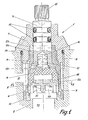
- valve insert 1 shows a valve insert 1 screwed into a fitting 2 with a valve spindle 3, which rotates a ceramic disk 5 in relation to another ceramic disk 6 via a driver 4.
- the parts mentioned are comprised on the one hand by a head piece designed as a union nut 7, screwed into the fitting 2 by means of a thread 8, and on the other hand by a housing 9 which, in the embodiment shown, is made of plastic.
- the ceramic disks 5 and 6 can be rotated between an open position and a blocking position for a flow, for example fresh water, which flows into the valve insert through an opening 10 and through an outlet opening 11 above the ceramic disk 5 again flows out.
- the outlet opening can be arranged elsewhere and can be configured differently than shown.
- the valve insert is described in more detail with reference to FIGS. 1 and 2.
- the insert consists of a preassembled unit in that the valve spindle 3 provided with O-rings 12, a thrust washer 13, the driver 4 and the ceramic disks 5 and 6 are inserted through the base 9 of the valve housing in the order given.
- the ceramic disk 6 is rotated into a position in which radially inwardly projecting projections 33 on the housing 9 come to rest in a recess 32 of the disk, in such a way that it is held in a rotationally fixed manner in relation to the housing 9.
- a stop ring 14 is pressed into the bottom of the valve housing 9, as a result of which the aforementioned parts are mutually fixed.
- valve housing 9 can be arranged in the fitting 2 and fastened by means of the union nut 7, whereby the valve partially is sealed by means of the O-rings 12 and partly by means of a further 0-ring 14.
- the stop ring 14 serves as a sealing ring between the fitting 2 and the ceramic disk 6. It follows from this that worn O-rings 12 can be replaced simply by removing the union nut 7 without the other parts of the valve insert becoming detached from one another.
- valve can be rotated between the open position and the blocking position, for which purpose a handle (not shown) is normally pressed onto a star groove 15 at the projecting end of the valve spindle 3.
- the opposite spindle end is formed with a square recess 16 for receiving a complementary pin 17 on the driver 4, which has projections 18 which engage in grooves in the ceramic disk 5.
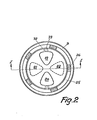
- FIG. 2 shows two complementary holes 21 and 22 in the ceramic disk 6 in broken lines.
- the valve is in its blocking position.
- the holes 19 and 20 are brought into a position aligned with one of the holes 21 and 22, which corresponds to the open valve position.
- the open position and the blocking position are defined by a pin 23 which projects radially outwards from the valve spindle and which receives a recess 24 in the head of the valve housing 9.
- the recess extends over a circular arc of 90 °.
- the pin rests on the bottom of the recess 24, which means that a handle can be opened onto the star groove 15 without the impact force propagating up to the ceramic disks 5 and 6, which could be destroyed as a result.
- the ceramic disks 5 and 6 are also secured against excessive stress by the free play between the recess 16 and the pin 17 and by the play between the projections 18 and the ceramic disk 5, which lies flat on the driver 4 outside the projections 18.
- the head of the valve housing 9 is preferably polygonal, for example hexagonal.
- the polygonal housing head interacts with complementary recesses in the union nut 7. If, for example, certain limit positions are desired for the handle when the valve is open and closed, it may be necessary in an embodiment with a square axis instead of the star groove 15 to provide an outlet opening aligned with the opening 11 in the housing 9. This limitation of the universal use of the valve insert is avoided according to the invention by a number of holes 25 (five holes are provided in FIG.
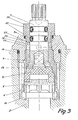
- valve insert can thus be used for fittings with an outlet opening 11 arranged in any manner above the ceramic disk 5. In Fig. 3, the outlet opening is not visible behind the driver.
- the embodiment of the valve insert according to the invention shown in FIG. 3 differs from the embodiment shown in FIG. 1 only in that the head piece consists of two parts, namely a part 27 provided with the thread cooperating with the fitting and one by means of a thread 29 part 28 which can be screwed into part 27 by ensuring a tight connection with the aid of an O-ring 30.
- the head part 28 extends in the axial direction past the O-rings 12.
- the head piece part 28 has a radially inwardly directed flange 31 which bears against the upper side of the valve housing 9.
- the O-rings 12 can be exchanged for water pressure without relieving the pressure on the fitting. This is based on the fact that the valve insert is held by the head part 27, while only the head part 28 has to be dismantled in order to replace the 0-rings 12.
- valve according to the invention represents a significant improvement in maintenance compared to the known valves, it is of course desirable to make the valve as universally usable as possible. This can be achieved, for example, by producing only two different valve housing sizes, after which the valve insert can be adapted to a large number of different fittings by providing several different union nuts, some of which are adapted to the depth of the valve opening and the thread dimensions and some to the shape of the desired handle are.
- valve spindles can be manufactured with different shapes to complete, for example, the star groove shown in the drawing figures.
Landscapes
- Engineering & Computer Science (AREA)
- General Engineering & Computer Science (AREA)
- Mechanical Engineering (AREA)
- Sliding Valves (AREA)
- Magnetically Actuated Valves (AREA)
- Valve Housings (AREA)
- Valve-Gear Or Valve Arrangements (AREA)
- Vaporization, Distillation, Condensation, Sublimation, And Cold Traps (AREA)
- Vessels And Coating Films For Discharge Lamps (AREA)
- Temperature-Responsive Valves (AREA)
- Compressor (AREA)
- Taps Or Cocks (AREA)
- Valve Device For Special Equipments (AREA)
- Fuel-Injection Apparatus (AREA)
Priority Applications (1)
| Application Number | Priority Date | Filing Date | Title |
|---|---|---|---|
| AT82104106T ATE23614T1 (de) | 1981-05-13 | 1982-05-12 | Ventiloberteil. |
Applications Claiming Priority (2)
| Application Number | Priority Date | Filing Date | Title |
|---|---|---|---|
| DK2115/81 | 1981-05-13 | ||
| DK211581A DK155198C (da) | 1981-05-13 | 1981-05-13 | Ventilindsats for iskruning i et armatur |
Publications (3)
| Publication Number | Publication Date |
|---|---|
| EP0065266A2 true EP0065266A2 (fr) | 1982-11-24 |
| EP0065266A3 EP0065266A3 (en) | 1983-01-12 |
| EP0065266B1 EP0065266B1 (fr) | 1986-11-12 |
Family
ID=8110182
Family Applications (1)
| Application Number | Title | Priority Date | Filing Date |
|---|---|---|---|
| EP82104106A Expired EP0065266B1 (fr) | 1981-05-13 | 1982-05-12 | Cartouche de robinet |
Country Status (5)
| Country | Link |
|---|---|
| EP (1) | EP0065266B1 (fr) |
| AT (1) | ATE23614T1 (fr) |
| DE (1) | DE3274284D1 (fr) |
| DK (1) | DK155198C (fr) |
| ES (1) | ES274460Y (fr) |
Cited By (11)
| Publication number | Priority date | Publication date | Assignee | Title |
|---|---|---|---|---|
| GB2185091A (en) * | 1986-01-04 | 1987-07-08 | Danfoss As | Valve assembly for a thermostatic valve |
| FR2620508A1 (fr) * | 1987-09-11 | 1989-03-17 | Kugler Fonderie Robinetterie | Partie superieure ou chapeau de robinet |
| EP0278301A3 (en) * | 1987-01-26 | 1989-04-26 | Jacuzzi Europe Spa | Air flow regulating and noise reducing assembly specificair flow regulating and noise reducing assembly specifically for hydromassage equipments ally for hydromassage equipments |
| EP0430896A3 (en) * | 1989-11-08 | 1991-07-24 | Galatron S.R.L. | Screw type valve with ceramic disks |
| FR2719884A1 (fr) * | 1994-05-13 | 1995-11-17 | Oras Oy | Robinet d'eau et élément de vanne pour le robinet. |
| WO1997010460A1 (fr) * | 1995-09-14 | 1997-03-20 | Ideal-Standard Gmbh | Partie superieure d'un robinet d'eau comportant des disques d'etancheite ceramiques situes dans le corps du robinet |
| EP0802361A3 (fr) * | 1996-04-15 | 1998-05-27 | Emhart Inc. | Ensemble de robinet |
| CN103195948A (zh) * | 2013-04-03 | 2013-07-10 | 台州朝日铜业有限公司 | 淋浴单摆调温陶瓷阀芯 |
| EP2829776A1 (fr) * | 2013-07-23 | 2015-01-28 | Flühs Drehtechnik GmbH | Partie supérieure de vanne d'arrêt |
| CN116398650A (zh) * | 2023-03-28 | 2023-07-07 | 江苏神通阀门股份有限公司 | 一种液氢用超低温截止阀 |
| WO2026025522A1 (fr) * | 2024-07-31 | 2026-02-05 | 广东汉特科技有限公司 | Robinet d'équerre et procédé d'assemblage |
Families Citing this family (3)
| Publication number | Priority date | Publication date | Assignee | Title |
|---|---|---|---|---|
| EP2225487B2 (fr) † | 2007-12-15 | 2016-11-23 | Grohe AG | Robinet d'eau chaude |
| DE202020000677U1 (de) * | 2019-02-27 | 2020-03-20 | Aptar Dortmund Gmbh | Ventil und Abgabevorrichtung |
| CN112576764A (zh) * | 2020-12-09 | 2021-03-30 | 徐连军 | 一种双向电磁阀 |
Family Cites Families (5)
| Publication number | Priority date | Publication date | Assignee | Title |
|---|---|---|---|---|
| US3780758A (en) * | 1972-11-15 | 1973-12-25 | Wolverine Brass Works Ind Inc | Non-metallic cartridge valve |
| CA998035A (en) * | 1973-02-26 | 1976-10-05 | American Standard Inc. | Ceramic disc faucet valve |
| DE2960712D1 (en) * | 1978-01-26 | 1981-11-26 | Ideal Standard Sa | Rotary valve |
| IT7934813U1 (it) * | 1979-02-23 | 1980-08-23 | Mingori Diffusion | Rubinetto di tipo perfezionato |
| US4331176A (en) * | 1980-03-03 | 1982-05-25 | American Standard Inc. | Replaceable cartridge valve assembly |
-
1981
- 1981-05-13 DK DK211581A patent/DK155198C/da not_active IP Right Cessation
-
1982
- 1982-05-12 EP EP82104106A patent/EP0065266B1/fr not_active Expired
- 1982-05-12 AT AT82104106T patent/ATE23614T1/de not_active IP Right Cessation
- 1982-05-12 ES ES1982274460U patent/ES274460Y/es not_active Expired
- 1982-05-12 DE DE8282104106T patent/DE3274284D1/de not_active Expired
Cited By (18)
| Publication number | Priority date | Publication date | Assignee | Title |
|---|---|---|---|---|
| GB2185091A (en) * | 1986-01-04 | 1987-07-08 | Danfoss As | Valve assembly for a thermostatic valve |
| GB2185091B (en) * | 1986-01-04 | 1990-06-20 | Danfoss As | Valve assembly for a thermostatic valve |
| EP0278301A3 (en) * | 1987-01-26 | 1989-04-26 | Jacuzzi Europe Spa | Air flow regulating and noise reducing assembly specificair flow regulating and noise reducing assembly specifically for hydromassage equipments ally for hydromassage equipments |
| FR2620508A1 (fr) * | 1987-09-11 | 1989-03-17 | Kugler Fonderie Robinetterie | Partie superieure ou chapeau de robinet |
| US4896693A (en) * | 1987-09-11 | 1990-01-30 | Kugler, Fonderie Et Robinetterie S.A. | Upper portion or cartridge of a tap |
| EP0430896A3 (en) * | 1989-11-08 | 1991-07-24 | Galatron S.R.L. | Screw type valve with ceramic disks |
| AU644114B2 (en) * | 1989-11-08 | 1993-12-02 | Galatron S.R.L. | Screw type valve with ceramic disks |
| FR2719884A1 (fr) * | 1994-05-13 | 1995-11-17 | Oras Oy | Robinet d'eau et élément de vanne pour le robinet. |
| WO1997010460A1 (fr) * | 1995-09-14 | 1997-03-20 | Ideal-Standard Gmbh | Partie superieure d'un robinet d'eau comportant des disques d'etancheite ceramiques situes dans le corps du robinet |
| EP0802361A3 (fr) * | 1996-04-15 | 1998-05-27 | Emhart Inc. | Ensemble de robinet |
| US5904336A (en) * | 1996-04-15 | 1999-05-18 | Emhart Inc. | Valve assembly |
| US5971359A (en) * | 1996-04-15 | 1999-10-26 | Emhart Inc. | Valve assembly |
| US6016830A (en) * | 1996-04-15 | 2000-01-25 | Emhart, Inc. | Valve assembly |
| CN103195948A (zh) * | 2013-04-03 | 2013-07-10 | 台州朝日铜业有限公司 | 淋浴单摆调温陶瓷阀芯 |
| CN103195948B (zh) * | 2013-04-03 | 2016-07-06 | 台州朝日铜业有限公司 | 淋浴单摆调温陶瓷阀芯 |
| EP2829776A1 (fr) * | 2013-07-23 | 2015-01-28 | Flühs Drehtechnik GmbH | Partie supérieure de vanne d'arrêt |
| CN116398650A (zh) * | 2023-03-28 | 2023-07-07 | 江苏神通阀门股份有限公司 | 一种液氢用超低温截止阀 |
| WO2026025522A1 (fr) * | 2024-07-31 | 2026-02-05 | 广东汉特科技有限公司 | Robinet d'équerre et procédé d'assemblage |
Also Published As
| Publication number | Publication date |
|---|---|
| EP0065266A3 (en) | 1983-01-12 |
| DK155198B (da) | 1989-02-27 |
| EP0065266B1 (fr) | 1986-11-12 |
| DK211581A (da) | 1982-11-14 |
| DE3274284D1 (de) | 1987-01-02 |
| ES274460U (es) | 1984-01-16 |
| ES274460Y (es) | 1984-08-16 |
| ATE23614T1 (de) | 1986-11-15 |
| DK155198C (da) | 1989-07-31 |
Similar Documents
| Publication | Publication Date | Title |
|---|---|---|
| EP0065266A2 (fr) | Cartouche de robinet | |
| DE69526520T2 (de) | Ventilanordnung | |
| DE3421653C2 (de) | Ventil | |
| DE202005003127U1 (de) | Ventiloberteil | |
| DE3513533A1 (de) | Kugelventil mit eingebautem rueckschlagventil | |
| EP0103710B1 (fr) | Partie supérieure de cartouche pour un robinet sanitaire d'arrêt | |
| EP0999389A2 (fr) | Bec verseur orientable avec un robinet mitigeur | |
| DE1147454B (de) | Absperrhahn | |
| DE664769C (de) | Rueckschlagventil zum Einbau in zylinderfoermige Druckbehaelter, Rohre o. dgl. | |
| DE2107645A1 (de) | Gehäuse für ein Absperrorgan | |
| DE202023102547U1 (de) | Verbindung für wasserführende Bauteile | |
| DE1019133B (de) | Absperrhahn mit Kugelkueken | |
| DE1550468B2 (de) | Doppelsitzventil | |
| DE3223356C2 (de) | Ventil | |
| DE69227256T2 (de) | Mengen-und temperaturbegrenzungsvorrichtung fuer ein mischventil | |
| DE2340051C2 (de) | Auswechselbare Rückdichtung an einem Absperrventil | |
| DE1241214B (de) | Absperrhahn | |
| DE2202594A1 (de) | Absperrorgan mit einem drehbaren verschlussteil | |
| DE1930733A1 (de) | Kugelhahn | |
| DE2924372C3 (de) | Ventil, insbesondere thermostatisch gesteuertes Heizkörperventil mit Voreinstellung | |
| DE3316659A1 (de) | Kugelventil | |
| DE681191C (de) | Rohrkupplung, insbesondere fuer Kaeltemittelleitungen | |
| DE107968C (fr) | ||
| DE2642641A1 (de) | Schutzkappe fuer absperrhaehne fuer zentralheizungen mit thermostatsteuerung | |
| DE2937617A1 (de) | Absperrhahn |
Legal Events
| Date | Code | Title | Description |
|---|---|---|---|
| PUAI | Public reference made under article 153(3) epc to a published international application that has entered the european phase |
Free format text: ORIGINAL CODE: 0009012 |
|
| PUAL | Search report despatched |
Free format text: ORIGINAL CODE: 0009013 |
|
| AK | Designated contracting states |
Designated state(s): AT CH DE FR GB IT NL SE |
|
| AK | Designated contracting states |
Designated state(s): AT CH DE FR GB IT LI NL SE |
|
| RHK1 | Main classification (correction) |
Ipc: F16K 3/08 |
|
| 17P | Request for examination filed |
Effective date: 19830627 |
|
| RAP1 | Party data changed (applicant data changed or rights of an application transferred) |
Owner name: AKTIESELSKABET NORDISKE KABEL-OG TRAADFABRIKER |
|
| GRAA | (expected) grant |
Free format text: ORIGINAL CODE: 0009210 |
|
| AK | Designated contracting states |
Kind code of ref document: B1 Designated state(s): AT CH DE FR GB IT LI NL SE |
|
| PG25 | Lapsed in a contracting state [announced via postgrant information from national office to epo] |
Ref country code: NL Effective date: 19861112 Ref country code: IT Free format text: LAPSE BECAUSE OF FAILURE TO SUBMIT A TRANSLATION OF THE DESCRIPTION OR TO PAY THE FEE WITHIN THE PRESCRIBED TIME-LIMIT;WARNING: LAPSES OF ITALIAN PATENTS WITH EFFECTIVE DATE BEFORE 2007 MAY HAVE OCCURRED AT ANY TIME BEFORE 2007. THE CORRECT EFFECTIVE DATE MAY BE DIFFERENT FROM THE ONE RECORDED. Effective date: 19861112 Ref country code: FR Free format text: THE PATENT HAS BEEN ANNULLED BY A DECISION OF A NATIONAL AUTHORITY Effective date: 19861112 |
|
| REF | Corresponds to: |
Ref document number: 23614 Country of ref document: AT Date of ref document: 19861115 Kind code of ref document: T |
|
| PG25 | Lapsed in a contracting state [announced via postgrant information from national office to epo] |
Ref country code: SE Effective date: 19861130 |
|
| REF | Corresponds to: |
Ref document number: 3274284 Country of ref document: DE Date of ref document: 19870102 |
|
| EN | Fr: translation not filed | ||
| NLV1 | Nl: lapsed or annulled due to failure to fulfill the requirements of art. 29p and 29m of the patents act | ||
| PG25 | Lapsed in a contracting state [announced via postgrant information from national office to epo] |
Ref country code: AT Effective date: 19870512 |
|
| PG25 | Lapsed in a contracting state [announced via postgrant information from national office to epo] |
Ref country code: LI Effective date: 19870531 Ref country code: CH Effective date: 19870531 |
|
| PLBE | No opposition filed within time limit |
Free format text: ORIGINAL CODE: 0009261 |
|
| STAA | Information on the status of an ep patent application or granted ep patent |
Free format text: STATUS: NO OPPOSITION FILED WITHIN TIME LIMIT |
|
| 26N | No opposition filed | ||
| REG | Reference to a national code |
Ref country code: CH Ref legal event code: PL |
|
| PGFP | Annual fee paid to national office [announced via postgrant information from national office to epo] |
Ref country code: GB Payment date: 19910502 Year of fee payment: 10 |
|
| PGFP | Annual fee paid to national office [announced via postgrant information from national office to epo] |
Ref country code: DE Payment date: 19910531 Year of fee payment: 10 |
|
| PG25 | Lapsed in a contracting state [announced via postgrant information from national office to epo] |
Ref country code: GB Effective date: 19920512 |
|
| GBPC | Gb: european patent ceased through non-payment of renewal fee |
Effective date: 19920512 |
|
| PG25 | Lapsed in a contracting state [announced via postgrant information from national office to epo] |
Ref country code: DE Effective date: 19930202 |