EP0065293A2 - Dispositif de nettoyage pour une broche d'une machine - Google Patents
Dispositif de nettoyage pour une broche d'une machine Download PDFInfo
- Publication number
- EP0065293A2 EP0065293A2 EP82104242A EP82104242A EP0065293A2 EP 0065293 A2 EP0065293 A2 EP 0065293A2 EP 82104242 A EP82104242 A EP 82104242A EP 82104242 A EP82104242 A EP 82104242A EP 0065293 A2 EP0065293 A2 EP 0065293A2
- Authority
- EP
- European Patent Office
- Prior art keywords
- cone
- cleaning
- spindle
- mandrel
- cleaning cone
- Prior art date
- Legal status (The legal status is an assumption and is not a legal conclusion. Google has not performed a legal analysis and makes no representation as to the accuracy of the status listed.)
- Granted
Links
Images

Classifications
-
- B—PERFORMING OPERATIONS; TRANSPORTING
- B23—MACHINE TOOLS; METAL-WORKING NOT OTHERWISE PROVIDED FOR
- B23Q—DETAILS, COMPONENTS, OR ACCESSORIES FOR MACHINE TOOLS, e.g. ARRANGEMENTS FOR COPYING OR CONTROLLING; MACHINE TOOLS IN GENERAL CHARACTERISED BY THE CONSTRUCTION OF PARTICULAR DETAILS OR COMPONENTS; COMBINATIONS OR ASSOCIATIONS OF METAL-WORKING MACHINES, NOT DIRECTED TO A PARTICULAR RESULT
- B23Q11/00—Accessories fitted to machine tools for keeping tools or parts of the machine in good working condition or for cooling work; Safety devices specially combined with or arranged in, or specially adapted for use in connection with, machine tools
- B23Q11/0042—Devices for removing chips
-
- B—PERFORMING OPERATIONS; TRANSPORTING
- B23—MACHINE TOOLS; METAL-WORKING NOT OTHERWISE PROVIDED FOR
- B23Q—DETAILS, COMPONENTS, OR ACCESSORIES FOR MACHINE TOOLS, e.g. ARRANGEMENTS FOR COPYING OR CONTROLLING; MACHINE TOOLS IN GENERAL CHARACTERISED BY THE CONSTRUCTION OF PARTICULAR DETAILS OR COMPONENTS; COMBINATIONS OR ASSOCIATIONS OF METAL-WORKING MACHINES, NOT DIRECTED TO A PARTICULAR RESULT
- B23Q2230/00—Special operations in a machine tool
- B23Q2230/002—Using the spindle for performing a non machining or non measuring operation, e.g. cleaning, actuating a mechanism
Definitions
- the invention relates to a device for cleaning the inner cone of a machine spindle, in particular the work spindle of a machine tool, with a cleaning body that can be inserted into the inner cone.
- the inner taper of a machine spindle is used to hold a correspondingly conical part that is to rotate with the spindle in order to fulfill a specific task. It can in particular be a tool, e.g. a boring tool or a milling tool, act, or else another object, for example a keyboard, measuring device or the like.
- the state of the inner cone of the spindle is decisive for the correct reception of the cone to be used and thus for the accuracy of a machining operation to be carried out, a measuring process or the like. Even small impurities can have a very unfavorable effect.
- the object of the invention is to provide a device for cleaning an inner cone, with the aid of which at least the cleaning process itself can be carried out without manual work.
- the invention aims to design the device so that the cleaning process can be carried out completely in an automatic sequence. All other related problems with which the invention is concerned result from the respective explanation of the indicated solution.
- the device has a sleeve-shaped cleaning cone or the like on a mandrel, neck. a Tragkörpe.rs is rotatably supported, means for effecting a relative rotation between the cleaning cone and the mandrel are present and wherein the device for performing the cleaning process on the spindle is releasably fixable.
- the invention provides for the device to be designed such that it can be used in an automatic tool changing system instead of a tool.
- a drive motor can be provided or a flywheel mass can be present and / or an element projecting outwards. by means of which the cleaning cone can be held against rotation while leaving the rotatability of the mandrel.
- a device is created with which the cleaning process in an inner cone can be carried out in a particularly favorable manner. There is no longer any dependence on the skill of an operator. Although inserting the device into the spindle and connecting to the latter.r as well as the removal after the cleaning process can be done by hand, the invention also offers the advantageous possibility to let the entire process including attaching and detaching the device run automatically.
- connection of the device to the spindle can be done in different ways, depending on the circumstances. it by means of a quick coupling of a principle known per se, be it by means of a union, by means of rear projections on the parts engaging on the spindle or in a similar manner. If the device at. a spindle can be used in which a clamping device for the releasable tightening of a tool or the like. is present, the device advantageously has a part cooperating with such a clamping device, for example a clamping mushroom at the end, just as is the case with tools or other objects that can be inserted into the spindle.
- the outside covering or trimming of the cleaning cone is made of a material that can remove existing contaminants from the inner cone without damaging its surface.
- a material that can remove existing contaminants from the inner cone without damaging its surface There are various materials that meet this requirement, including also suitable plastics.
- a wholly or partially brush-like trim or bristles or similar elements on the top is possible.
- This covering can also consist entirely or partially of leather.
- the trim can cover the entire outside of the cleaning cone or even only a part thereof.
- the trim is in the form of a ribbon or strip. It can run like a helix.
- the trim can also have parts extending in the direction of the cone surface lines or be formed by such.
- passage paths for a rinsing medium are provided in the area of the covering or trimming of the cleaning cone. These can be formed, in particular, by spaces between band-shaped or strip-shaped parts of the covering or trimmings.
- a gaseous medium namely air
- the flushing medium is advantageously supplied at the front end of the device, for which purpose an inlet point is provided in this area. This is particularly cheap if possible speed exists to supply compressed air through the inside of the spindle, as with. numerous machines is also the case for other purposes.
- a seal suitable for bearing against the front end of the machine spindle having the inner cone to be cleaned can be provided on the support body. It is then ensured that no flushing medium can escape in an undesirable manner at this point.
- the cleaning cone or the like on the mandrel. the support body axially slidably mounted. This also makes it possible. at. existing tolerances a secure contact of the covering or trimmings carried by the cleaning cone on the inner cone. It can be advantageous in a further embodiment that the cleaning cone is under the action of at least one spring looking to move it outward in the direction of the spindle and comes into contact with the inner cone and a stop limiting the displacement when the device is removed is present.
- the cleaning cone drive motor is a compressed air motor.
- the supply of compressed air can. be provided from the outside. It is particularly favorable to use purge air for the cleaning cone as the operating medium for the drive motor.
- the support body has a current source for the drive motor, for example a battery or an accumulator, so that the device also forms an independent unit in this case.
- a key switch is advantageously provided for switching the drive on and off.
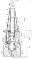
- a work spindle S (for example the spindle of a boring and milling machine) with an inner cone K for holding tools with a corresponding cone is shown in FIG. 2, but without the reproduction of a clamping device.
- the device shown contains one composed of several parts, in total with the number 1 designated support body. From this arises a mandrel 2 which is rigidly connected to the support body 1 by a self-locking nut 3, so that the support body forms a unit with the mandrel.
- a sleeve-shaped cone 5 is rotatably mounted on the mandrel 2 via roller bearings 4, a sliding bearing would also be possible.
- the conical surface 5 is provided with a trim in the form of a helical band 6.
- this consists of a brush-like element in the form of a carrier 6b provided with bristles 6a.
- the trim can also be formed by bands running in the direction of the cone surface lines or other shaped parts, as in FIG. the number 6 'is indicated.
- the cone 5 is fixedly connected to a bushing 7, which is designed as a gear 8 in its rear part. This engages the end of a pinion 9, which is mounted in the support body 1 in roller bearings 10 and has a gear 12 at its other end.
- a drive pinion 13 seated on the output shaft 14 of a motor 15 engages in this.
- the motor held in a cover part 1a of the support body 1 is shown in FIG. 2 as well as other parts are shown offset by 90 ° for the sake of clarity. Therefore, the engagement of the pinion 13 in the gear 12 is indicated by dash-dotted lines 13a. It is thus possible to drive the cleaning cone 5 in a rotating manner by means of the motor 15 via the two gear stages.
- the mandrel 2 is formed at its front end as a tensioning mushroom 16, such that it can cooperate with a tensioning device assigned to the spindle S.
- tensioning devices are known in numerous designs, e.g. for horizontal boring and milling machines. When clamping by means of such a device, an area on the end face of the support body 1 or a ring 17 attached there comes to rest on the end face of the work spindle S.
- the trim 6 of the cleaning cone 5 is in this working position of the device on the inner cone K, so that when the cone is rotated by the motor 15 it sweeps over the entire cone surface and thereby cleans it of impurities.
- the cleaning cone 5 is axially displaceable to a limited extent in addition to its rotatable arrangement on the mandrel 2. According to an advantageous feature, it is under the effect of a plurality of compression springs 18 arranged distributed over the circumference, which are accommodated in the support body 1 and of which only one can be seen in FIG. 2.
- the compression springs act on the sleeve via an axial bearing 19. 7 or egg- on this bearing ring.
- pins 20 which in holes 21 of the support body grip, there is an anti-twist device.
- the axial displacement path of the cleaning cone 5 on the mandrel 2 is limited at the front by a stop 22.
- the cleaning effect is at. the reproduced version of the device is further supported by the fact that air is used as the flushing medium. It is provided that compressed air, which is available at numerous locations at one point within the work spindle, enters the front opening 23 in the tensioning mushroom 16 when the device is clamped in the direction of the arrow shown in FIG. 2 and through one or more bores 24 enters the space between the inner cone K of the spindle S and the cleaning cone 5. It can then take its way through the passage paths 26 which also remain between the helically attached trimmings 6 and then passes through bores 25 in the support body 1 into an interior space 27 thereof. If the motor 15 is designed as an air motor, as in.
- This embodiment is the case, it can be supplied directly by the purge air, so that no special air supply to the engine from the outside is required.
- the air comes from the interior 27 through a filter 28 and a pipe 29 to the inlet port 30 of the engine 15
- the exhaust air of the same can flow out of an outlet connection 31.
- a sealing ring 32 is provided, which comes to rest on the front end of the work spindle S, as can be seen from FIG. 2.
- the contact of the sealing ring 32 with one of the driver blocks M which are usually present on a work spindle and engage in grooves in a tool body can also be seen.
- the driving stone M is suitably adapted on the inside to the contour of the inner cone K.
- the supporting body 1, like corresponding tools, is provided with recesses 33 in which the driver blocks can engage.
- another drive for the cleaning cone can also be present, in particular a small electric motor, which is then attached to the supporting body 1 in a corresponding manner.
- a battery or the like arranged on or in the support body is then expedient for its power supply. intended. If a purge with air or another medium is also provided. can if necessary. Seal 32 is omitted so that the air can escape at the front end of the spindle.
- the device advantageously has a switch, in particular a pushbutton switch, which is arranged such that an electric motor as a drive for the cleaning cone is switched on when the device is inserted into the spindle and is switched off when it is removed from the spindle.
- a switch 35 is shown in dash-dotted lines, which can cooperate with the end face of the spindle in question.
- the entire device is designed so that it can take a place in a magazine of an automatic tool changing device instead of a tool and can be used instead of a tool in the spindle of the associated machine and removed from it again and returned to the memory.
- the support body 1 has an annular groove 34 on which the pliers or the gripper of a transfer member of a tool changer can engage. Codings known per se can also be present. In any case, too. with space coding, it is advantageously possible to automatically insert the cleaning device into the spindle at a desired point in time and to clean its inner cone. This can be provided at a specific point in a program run and, if necessary, can also be carried out at any time upon additional command.
- FIG. 3 is one. Execution of the device shown, which does not contain a motor, but allows the cleaning cone 5 to be rotated in another way. As in the embodiment according to FIG. 2, the cleaning cone 5 is rotatably mounted on the mandrel 2 and can also be axially displaced thereon to a limited extent. 2 or similar parts are the same in FIG. 3. Reference numbers as indicated there. The corresponding explanations for FIG. 2 therefore also apply here.
- the stocking of the cleaning cone 5 is formed by strips 6 'made of a suitable material, which run in the direction of the surface lines (cf. also FIG. 1).
- a gear 41 in the mesh With the gear 12 of the transmission is a gear 41 in the mesh, which is firmly seated at the end of a shaft 42. This is mounted centrally in a bearing flange 44 connected to the support body 1 by screws 43 in ball bearings 45.
- a flywheel 50 On the other end of the shaft 42, a flywheel 50 is non-rotatably but releasably fastened by means of a parallel key 46 and a self-locking nut 47.
- the flywheel 50 consists of a housing 48 with a filling 49 made of a heavy material, e.g. Lead.
- the device is removed from a magazine, for example with the aid of a conventional tool changing device, and inserted into the inner cone of the machine spindle (cf. also FIG. 2). While the tool changing device gets the next tool for machining from the magazine, the work spindle is briefly rotated and immediately. slowed down or stopped again, which can happen automatically as part of the tool change process. While the machine spindle is starting up, the flywheel 50 initially remains behind due to its inertia during the rotary movement and is only gradually accelerated. When the work spindle is stopped, the flywheel 50 continues to run before it comes to rest. By a such.
- Delayed and trailing rotation of the flywheel 50 is achieved via the gear 41, 12, 11, 9 and 8, a relative movement between the cleaning cone 5 and the inner cone of the work spindle and thus the cleaning process by means of the trim 6 'of the cleaning cone 5.
- the gear 8, 9, 11, 12, 41 is step-down.
- other designs are also possible, for example a ratio of 1: 1 or greater.
- the flywheel can also be connected directly to a cleaning cone 5 or even be formed by the latter itself. In the latter. In this case, the cleaning cone receives a correspondingly heavy training.
- an outwardly protruding lever 51 is provided, which is connected to the cleaning cone 5 directly or via a gear or other intermediate elements so that when this lever 51 is held, the cleaning cone 5 also prevents rotation is.
- the holding of the lever 51 expediently takes place in such a way that it comes to rest against a fixed stop A, which is e.g. on the machine part containing the machine spindle, for example a headstock or the like, or at another suitable location.
- the lever 51 can also be designed and attached in such a way that it can deflect in a direction other than the stop direction or is flexible.
- the lever 51 is only for the sake of simplicity of illustration than on the housing 48 of the flywheel 5o attached drawn. However, there is no need for a flywheel, but the lever 51 can be attached to any suitable part of the device which is directly or indirectly connected to the cleaning cone 5, for example on the shaft 42 or also on a gear member, for example a gearwheel , Gear rim or the like.
- the cleaning cone 5 according to the invention can also be provided with a trim in the form of individual movably held or supported elements instead of with a fixed trim.
- a trim in the form of individual movably held or supported elements instead of with a fixed trim.
- the cleaning cone Provide on the circumference of the cleaning cone small cylindrical, conical or even round cleaning elements with bristles or other surface suitable for cleaning, which are rotatably mounted on axes which are held in the cleaning cone. It is also possible to give such elements a rotary movement, e.g. or the like on the principle of a planetary gear.
Landscapes
- Engineering & Computer Science (AREA)
- Mechanical Engineering (AREA)
- Auxiliary Devices For Machine Tools (AREA)
- Turning (AREA)
- Cleaning In General (AREA)
- Automatic Tool Replacement In Machine Tools (AREA)
Priority Applications (1)
| Application Number | Priority Date | Filing Date | Title |
|---|---|---|---|
| AT82104242T ATE14851T1 (de) | 1981-05-16 | 1982-05-14 | Reinigungsvorrichtung fuer maschinenspindeln. |
Applications Claiming Priority (2)
| Application Number | Priority Date | Filing Date | Title |
|---|---|---|---|
| DE3119597A DE3119597C2 (de) | 1981-05-16 | 1981-05-16 | "Reinigungsvorrichtung für Maschinenspindeln" |
| DE3119597 | 1981-05-16 |
Publications (3)
| Publication Number | Publication Date |
|---|---|
| EP0065293A2 true EP0065293A2 (fr) | 1982-11-24 |
| EP0065293A3 EP0065293A3 (en) | 1983-07-06 |
| EP0065293B1 EP0065293B1 (fr) | 1985-08-14 |
Family
ID=6132528
Family Applications (1)
| Application Number | Title | Priority Date | Filing Date |
|---|---|---|---|
| EP82104242A Expired EP0065293B1 (fr) | 1981-05-16 | 1982-05-14 | Dispositif de nettoyage pour une broche d'une machine |
Country Status (5)
| Country | Link |
|---|---|
| US (1) | US4468834A (fr) |
| EP (1) | EP0065293B1 (fr) |
| JP (1) | JPS57194852A (fr) |
| AT (1) | ATE14851T1 (fr) |
| DE (2) | DE3119597C2 (fr) |
Cited By (5)
| Publication number | Priority date | Publication date | Assignee | Title |
|---|---|---|---|---|
| DE3518902A1 (de) * | 1985-05-25 | 1986-11-27 | Schaudt Maschinenbau Gmbh, 7000 Stuttgart | Vorrichtung zur identifikation von schleifscheiben |
| EP0420039A3 (en) * | 1989-09-29 | 1991-06-12 | Starrfraesmaschinen Ag | Cleaning device for the holding shank of a tool or tool-holder |
| FR2977516A1 (fr) * | 2011-07-06 | 2013-01-11 | Renault Sa | Outil pour le nettoyage d'une broche rotative |
| WO2021048414A1 (fr) * | 2019-09-13 | 2021-03-18 | Wto Vermögensverwaltung Gmbh | Porte-outil entraîné comportant de multiples turbines |
| CN115771186A (zh) * | 2023-02-10 | 2023-03-10 | 江苏华雕机械有限公司 | 一种可清洁电主轴刀座的刀具 |
Families Citing this family (20)
| Publication number | Priority date | Publication date | Assignee | Title |
|---|---|---|---|---|
| DE3320598C2 (de) * | 1983-06-08 | 1986-10-16 | Werner und Kolb Werkzeugmaschinen GmbH, 1000 Berlin | Werkzeugmaschine mit einer Vorrichtung zum Entfernen von Bearbeitungsrückständen |
| JPS6034245A (ja) * | 1983-08-08 | 1985-02-21 | Kyoritsu Seiki Kk | 工作機械のスピンドル孔清掃装置 |
| JPS6067836U (ja) * | 1983-10-14 | 1985-05-14 | ヤマザキマザック株式会社 | スピンドルクリ−ニングツ−ル |
| JPS60153737U (ja) * | 1984-03-22 | 1985-10-14 | 株式会社 日研工作所 | 工具取付穴清掃装置 |
| JPS6175947U (fr) * | 1984-10-19 | 1986-05-22 | ||
| JPH0340522Y2 (fr) * | 1985-09-12 | 1991-08-26 | ||
| US5165133A (en) * | 1991-12-16 | 1992-11-24 | Armbruster Franz O | Socket cleaner |
| DE4228268C2 (de) * | 1992-08-31 | 1999-10-28 | Kelch & Co Werkzeugmaschf | Behandlungsgerät für Werkzeughalter o. dgl., insbesondere Reinigungsgerät |
| DE4403327A1 (de) * | 1994-02-03 | 1995-08-10 | Karl Bauch | Reinigungsvorrichtung an mehrachsigen Werkzeugmaschinen |
| USD387523S (en) * | 1995-11-21 | 1997-12-09 | Armbruster Franz O | Socket cleaner |
| US5782592A (en) * | 1996-10-10 | 1998-07-21 | Row; John W. | High speed spindle socket cleaning tool |
| DE20003921U1 (de) * | 2000-03-06 | 2000-07-20 | Bayer, Manfred, 72663 Großbettlingen | Kegelreiniger mit angetriebenem und auswechselbaren Kopf verschiedener Größen, zum Säubern von Kegeln in Werkzeugaufnahmen |
| JP3761545B2 (ja) * | 2003-07-07 | 2006-03-29 | ファナック株式会社 | 工作機械の自動工具交換装置 |
| CA2464275A1 (fr) * | 2004-04-14 | 2005-10-14 | Antoni Binek | Dispositif pour enlever les debris de l'alesage d'un cylindre, et methode de fonctionnement connexe |
| KR100662606B1 (ko) * | 2006-04-12 | 2006-12-28 | 수성정밀기계(주) | 포구자동청소기 |
| DE102007034140B4 (de) * | 2006-11-30 | 2011-05-12 | Gunther Schwarz Gmbh | Instandsetzungswerkzeug |
| KR100822411B1 (ko) * | 2007-02-15 | 2008-04-16 | 수성정밀기계(주) | 강선이 있는 포구 자동 청소 장치 |
| JP5376849B2 (ja) * | 2008-07-11 | 2013-12-25 | トヨタ自動車株式会社 | マシニングセンタの清掃装置 |
| US20140073229A1 (en) * | 2012-09-08 | 2014-03-13 | Ssdb, Llc | Interchangeable Polishing and Buffing Device |
| CN109465270B (zh) * | 2018-12-04 | 2023-10-03 | 西安精雕软件科技有限公司 | 一种锥孔清洁装置及清洗方法 |
Family Cites Families (11)
| Publication number | Priority date | Publication date | Assignee | Title |
|---|---|---|---|---|
| DD86549A (fr) * | 1900-01-01 | |||
| DE383631C (de) * | 1923-10-15 | Karl Geyer | Tragbare Vorrichtung zum Reinigen von Trinkglaesern | |
| US1393663A (en) * | 1918-05-01 | 1921-10-11 | Wilfred A Carver | Fountain-feed rotary brush |
| US1475079A (en) * | 1920-06-08 | 1923-11-20 | Miller Fred William | Rotary brush |
| US1706302A (en) * | 1925-12-31 | 1929-03-19 | Leavy Oscar | Apparatus for washing tumblers |
| US1611874A (en) * | 1926-04-16 | 1926-12-28 | Frederick W Becker | Vehicle washer |
| US1895532A (en) * | 1931-10-05 | 1933-01-31 | Backstrom Sven | Buffer |
| US2911665A (en) * | 1955-12-19 | 1959-11-10 | Cleveland Pneumatic Ind Inc | Tube cleaning device |
| DE1428388A1 (de) * | 1963-04-30 | 1968-12-12 | Electrostar Gmbh | Reinigungsvorrichtung fuer Schuhzeug,Polsterungen od.dgl. |
| CH615105A5 (en) * | 1977-10-17 | 1980-01-15 | Dixi Sa | Apparatus for cleaning the spindle taper holes of machine tools and use thereof |
| DE3005860A1 (de) * | 1980-02-16 | 1981-09-03 | Robert Bosch Gmbh, 7000 Stuttgart | Handwerkzeugmaschine, insbesondere blechnager |
-
1981
- 1981-05-16 DE DE3119597A patent/DE3119597C2/de not_active Expired
-
1982
- 1982-05-12 US US06/377,427 patent/US4468834A/en not_active Expired - Fee Related
- 1982-05-14 EP EP82104242A patent/EP0065293B1/fr not_active Expired
- 1982-05-14 DE DE8282104242T patent/DE3265391D1/de not_active Expired
- 1982-05-14 AT AT82104242T patent/ATE14851T1/de not_active IP Right Cessation
- 1982-05-17 JP JP57081701A patent/JPS57194852A/ja active Pending
Cited By (7)
| Publication number | Priority date | Publication date | Assignee | Title |
|---|---|---|---|---|
| DE3518902A1 (de) * | 1985-05-25 | 1986-11-27 | Schaudt Maschinenbau Gmbh, 7000 Stuttgart | Vorrichtung zur identifikation von schleifscheiben |
| EP0420039A3 (en) * | 1989-09-29 | 1991-06-12 | Starrfraesmaschinen Ag | Cleaning device for the holding shank of a tool or tool-holder |
| FR2977516A1 (fr) * | 2011-07-06 | 2013-01-11 | Renault Sa | Outil pour le nettoyage d'une broche rotative |
| WO2021048414A1 (fr) * | 2019-09-13 | 2021-03-18 | Wto Vermögensverwaltung Gmbh | Porte-outil entraîné comportant de multiples turbines |
| CN114450114A (zh) * | 2019-09-13 | 2022-05-06 | Wto资产管理有限公司 | 具有多个涡轮的从动工具架 |
| CN114450114B (zh) * | 2019-09-13 | 2024-05-24 | Wto资产管理有限公司 | 具有多个涡轮的从动工具架 |
| CN115771186A (zh) * | 2023-02-10 | 2023-03-10 | 江苏华雕机械有限公司 | 一种可清洁电主轴刀座的刀具 |
Also Published As
| Publication number | Publication date |
|---|---|
| EP0065293A3 (en) | 1983-07-06 |
| DE3119597C2 (de) | 1983-04-14 |
| ATE14851T1 (de) | 1985-08-15 |
| EP0065293B1 (fr) | 1985-08-14 |
| US4468834A (en) | 1984-09-04 |
| DE3265391D1 (en) | 1985-09-19 |
| JPS57194852A (en) | 1982-11-30 |
| DE3119597A1 (de) | 1983-01-13 |
Similar Documents
| Publication | Publication Date | Title |
|---|---|---|
| EP0065293A2 (fr) | Dispositif de nettoyage pour une broche d'une machine | |
| EP0301201B1 (fr) | Outil à mains à moteur électrique | |
| DE19951264A1 (de) | Werkzeugmaschine mit vereinfachtem Werkzeugwechsel | |
| DE10109956B4 (de) | Handwerkzeugmaschine mit einem Vorsatzgerät | |
| DE102007054883A1 (de) | Chipreinigungsvorrichtung in einer NC-Bearbeitungsmaschine | |
| DE102009019867A1 (de) | Rohrbearbeitungsvorrichtung zum Bearbeiten eines rohrförmigen Körpers | |
| DE4037944C2 (de) | Handgerät für eine Gewindebearbeitung | |
| EP3370571B1 (fr) | Procédé d'appointissage mécanique de poils et dispositif de meulage | |
| CH680914A5 (fr) | ||
| EP0458014A2 (fr) | Dispositif pour nettoyer des porte-outils | |
| EP1179388B1 (fr) | Procédé pour le nettoyage de queues d'outils et dispositif pour la mise en oeuvre de ce procédé | |
| DE19619202B4 (de) | Vorrichtung zum Reinigen und/oder Entgraten von Werkstücken mittels wenigstens eines Flüssigkeits-Spritzstrahls | |
| DE29907571U1 (de) | Späneleiteinrichtung für ein Zerspanaggregat und Zerspanaggregat mit einer solchen Späneleiteinrichtung | |
| DE10013984A1 (de) | Werkzeugmaschine mit vereinfachtem Werkzeugwechsel | |
| WO1999056919A1 (fr) | Machine-outil a changement d'outil | |
| DE102004019936B4 (de) | Drehmaschine, insbesondere Mehrspindeldrehautomat | |
| DE672422C (de) | Drehbare, zur Bearbeitung hohler Werkstuecke dienende Zufuehrungshuelse mit seitlicher Ein- und Auslassoeffnung | |
| DE102019117812B3 (de) | Drehwerkzeug-Handmaschine | |
| EP0920950B1 (fr) | Outil à main | |
| EP1769883B1 (fr) | Dispositif pour nettoyage de la tige et de la surface de contact d'une machine outil | |
| EP0030674B1 (fr) | Dispositif de changement d'outils pour machine-outils, en particulier pour aléseuses-fraiseuses horizontales | |
| DE19821337C1 (de) | Handwerkzeugmaschine mit vereinfachtem Werkzeugwechsel | |
| DE9018069U1 (de) | Hand-Nachbearbeitungs- und/oder Reinigungsgerät für Innen- und/oder Außengewinde | |
| DE2830172C2 (de) | Vorrichtung zur Reinigung der inneren Wandungen von Koks- oder Schwelgasleitungen | |
| DE2732882C3 (de) | Einrichtung zur Reinigung des Innengewindes von Muttern |
Legal Events
| Date | Code | Title | Description |
|---|---|---|---|
| PUAI | Public reference made under article 153(3) epc to a published international application that has entered the european phase |
Free format text: ORIGINAL CODE: 0009012 |
|
| AK | Designated contracting states |
Designated state(s): AT CH DE FR GB IT SE |
|
| PUAL | Search report despatched |
Free format text: ORIGINAL CODE: 0009013 |
|
| AK | Designated contracting states |
Designated state(s): AT CH DE FR GB IT LI SE |
|
| 17P | Request for examination filed |
Effective date: 19830810 |
|
| ITF | It: translation for a ep patent filed | ||
| GRAA | (expected) grant |
Free format text: ORIGINAL CODE: 0009210 |
|
| AK | Designated contracting states |
Designated state(s): AT CH DE FR GB IT LI SE |
|
| REF | Corresponds to: |
Ref document number: 14851 Country of ref document: AT Date of ref document: 19850815 Kind code of ref document: T |
|
| REF | Corresponds to: |
Ref document number: 3265391 Country of ref document: DE Date of ref document: 19850919 |
|
| ET | Fr: translation filed | ||
| REG | Reference to a national code |
Ref country code: GB Ref legal event code: 746 |
|
| PLBE | No opposition filed within time limit |
Free format text: ORIGINAL CODE: 0009261 |
|
| STAA | Information on the status of an ep patent application or granted ep patent |
Free format text: STATUS: NO OPPOSITION FILED WITHIN TIME LIMIT |
|
| 26N | No opposition filed | ||
| PGFP | Annual fee paid to national office [announced via postgrant information from national office to epo] |
Ref country code: SE Payment date: 19910425 Year of fee payment: 10 |
|
| PGFP | Annual fee paid to national office [announced via postgrant information from national office to epo] |
Ref country code: AT Payment date: 19910426 Year of fee payment: 10 |
|
| PGFP | Annual fee paid to national office [announced via postgrant information from national office to epo] |
Ref country code: GB Payment date: 19910502 Year of fee payment: 10 |
|
| PGFP | Annual fee paid to national office [announced via postgrant information from national office to epo] |
Ref country code: FR Payment date: 19910528 Year of fee payment: 10 |
|
| PGFP | Annual fee paid to national office [announced via postgrant information from national office to epo] |
Ref country code: CH Payment date: 19910529 Year of fee payment: 10 |
|
| ITTA | It: last paid annual fee | ||
| PG25 | Lapsed in a contracting state [announced via postgrant information from national office to epo] |
Ref country code: GB Effective date: 19920514 Ref country code: AT Effective date: 19920514 |
|
| PG25 | Lapsed in a contracting state [announced via postgrant information from national office to epo] |
Ref country code: SE Effective date: 19920515 |
|
| PG25 | Lapsed in a contracting state [announced via postgrant information from national office to epo] |
Ref country code: LI Effective date: 19920531 Ref country code: CH Effective date: 19920531 |
|
| GBPC | Gb: european patent ceased through non-payment of renewal fee |
Effective date: 19920514 |
|
| PG25 | Lapsed in a contracting state [announced via postgrant information from national office to epo] |
Ref country code: FR Effective date: 19930129 |
|
| REG | Reference to a national code |
Ref country code: CH Ref legal event code: PL |
|
| REG | Reference to a national code |
Ref country code: FR Ref legal event code: ST |
|
| EUG | Se: european patent has lapsed |
Ref document number: 82104242.1 Effective date: 19921204 |
|
| PGFP | Annual fee paid to national office [announced via postgrant information from national office to epo] |
Ref country code: DE Payment date: 19950420 Year of fee payment: 14 |
|
| PG25 | Lapsed in a contracting state [announced via postgrant information from national office to epo] |
Ref country code: DE Effective date: 19970201 |