EP0065314B1 - Poutre pour coffrages - Google Patents
Poutre pour coffrages Download PDFInfo
- Publication number
- EP0065314B1 EP0065314B1 EP19820104352 EP82104352A EP0065314B1 EP 0065314 B1 EP0065314 B1 EP 0065314B1 EP 19820104352 EP19820104352 EP 19820104352 EP 82104352 A EP82104352 A EP 82104352A EP 0065314 B1 EP0065314 B1 EP 0065314B1
- Authority
- EP
- European Patent Office
- Prior art keywords
- formwork
- flange
- girder
- web
- tab
- Prior art date
- Legal status (The legal status is an assumption and is not a legal conclusion. Google has not performed a legal analysis and makes no representation as to the accuracy of the status listed.)
- Expired
Links
Images


Classifications
-
- E—FIXED CONSTRUCTIONS
- E04—BUILDING
- E04G—SCAFFOLDING; FORMS; SHUTTERING; BUILDING IMPLEMENTS OR AIDS, OR THEIR USE; HANDLING BUILDING MATERIALS ON THE SITE; REPAIRING, BREAKING-UP OR OTHER WORK ON EXISTING BUILDINGS
- E04G11/00—Forms, shutterings, or falsework for making walls, floors, ceilings, or roofs
- E04G11/06—Forms, shutterings, or falsework for making walls, floors, ceilings, or roofs for walls, e.g. curved end panels for wall shutterings; filler elements for wall shutterings; shutterings for vertical ducts
- E04G11/062—Forms for curved walls
-
- E—FIXED CONSTRUCTIONS
- E04—BUILDING
- E04G—SCAFFOLDING; FORMS; SHUTTERING; BUILDING IMPLEMENTS OR AIDS, OR THEIR USE; HANDLING BUILDING MATERIALS ON THE SITE; REPAIRING, BREAKING-UP OR OTHER WORK ON EXISTING BUILDINGS
- E04G11/00—Forms, shutterings, or falsework for making walls, floors, ceilings, or roofs
- E04G11/04—Forms, shutterings, or falsework for making walls, floors, ceilings, or roofs for structures of spherical, spheroid or similar shape, or for cupola structures of circular or polygonal horizontal or vertical section; Inflatable forms
Definitions
- the invention relates to a formwork support for formwork constructions for round buildings with a shape that changes over their height, consisting of a profile support with two flanges arranged at a distance from one another and at least one web connecting the flanges, the support having at least one bend, and on the bend the opposite flange opposite the flange and the web of the profile carrier is provided with an incision transversely to the longitudinal direction of the profile carrier, and at least one correspondingly bent tab bridges the incision, and is connected to the two separate flange parts of the counter flange.
- the US-PS 17 47 362 shows such a construction of a girder, but it is not a formwork girder, but an arch of a steel structure.
- the bow is rigid.
- US Pat. No. 524,807 also shows a steel construction carrier with rigid bends.
- a foldable formwork is known from US Pat. No. 1,214,233, but it is not very dimensionally stable at the fold points.
- Formwork girders of the type mentioned at the outset have become known, for example, for formwork of buckled walls, the formwork panels being fastened to a flange of the profile girder. So far, one has separated the profile beam in the kink, cut and welded the end faces according to the kink angle. This method requires a considerable amount of work, which inhibits rapid assembly of the formwork scaffold. In addition, the kink angle of the profile beam can neither be corrected nor changed, for example in order to be able to use one and the same profile beam for formwork of walls with different kink angles.
- the object of the invention is to avoid these disadvantages and to provide a formwork support for formwork constructions which is provided with at least one bend and which permits angled bend which is correct in terms of assembly and is technically secure, and a simple correction or change in the articulation angle.
- the one flange is continuous and bend-deformable to change the bending angle
- the tab is screwed to the flange parts of the counter flange and has elongated holes which extend in the longitudinal direction of the profile beam and through which the fastening screws protrude.
- the invention can be used advantageously for formwork beams for buckled walls, which also include “curved” walls approximated by polyhedra.
- the invention can, however, also be used in formwork construction for beams which do not directly serve as beams for formwork panels, but with an otherwise load-bearing function, e.g. B. are arranged in the scaffolding or work scaffolding of a formwork construction, and there have one or more kinks, for example in the case of a polygonal course of the girder.
- the invention also enriches the assembly technology beyond the field of formwork construction.
- the formwork support according to the invention is used in particular in formwork for water towers, television towers, water containers, egg-shaped digesters and the like.
- the formwork girders which run in height, have been shaped and welded accordingly.
- the formwork support according to the invention can be adapted in a simple manner to any building shape, its adaptability being determined only by the distance between the bends. Furthermore, the formwork support according to the invention can be quickly reassembled, i.e. H. can be adapted to another formwork with a different curve.
- the formwork support according to the invention can also be used as a horizontal polygonal pressure or pull ring of a formwork scaffold for round buildings.
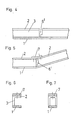
- FIG. 1 shows in view (partially cut) the kink of a formwork beam
- FIG. 2 shows a section according to 11-11 of FIG. 1
- Fig. Shows a variant for the tab
- FIG. 4 shows a formwork beam with an incision for a “convex kink”
- FIG. 5 shows the same formwork beam in the kinked position
- 6 and 7 show profile variants for the formwork beam
- FIG. 8 shows an application example of a formwork beam according to the invention.
- the formwork girder 10 is an I-section girder made of steel with the two flanges 1, 2 and the web 3.
- the formwork panels 4, which are offset on the edge side, are fastened to the flange 1 (fastening flange), with the help of the spreader bars 5.
- the formwork support 10 is provided with an incision 6 transverse to a longitudinal direction, which extends over the flange 2 (counter flange) opposite the mounting flange 1 and the entire web 3, but not into the continuous mounting flange 1 a penetrates. Then the carrier parts lying on both sides of the incision 6 are bent against one another in accordance with the required bending angle.
- the incision 6 is bridged by a tab 7 made of steel, which is connected to the counter flange 2, the nuts 9 being tightened with a torque wrench.
- the tab 7 expediently has the width of the counter flange 2 and is dimensioned in accordance with the tensile and compressive loads that occur.
- the connection of the carrier parts, which are partially separated by the incision 6, via the screwed tab 7 is a friction connection.
- the tab 7 has elongated holes 11, which allow the tab 7 to be adapted to different bending angles.
- the buttons of the screws 8 are underlaid by washers 10 '.
- FIG. 3 shows a tab 1 that is particularly easily adaptable to different articulation angles.
- the tab 7 has a hinge joint in the central region.
- the holes for the passage of the fastening screws are elongated holes.
- Fig. 1 shows a kink with a "concave” kink.
- the measures according to the invention can also be used for kinks with a «convex kink.
- a slightly modified incision 6 'of the counter flange 2 and the web 3 is required, which makes it possible for the continuous flange 1 to be bent in the manner shown in FIG. 5.
- the cut 6 ' is in turn bridged by a correspondingly bent tab 7 which is screwed to the counter flange 2.
- the formwork beam 10 need not necessarily be an I-beam.
- the adjustable buckling of the carrier according to the invention can also be achieved with other profile carriers, for. 6 or box section beams according to FIG. 7, in which case the counter flange 2 and the web (s) 3 are cut at the kink, but not the continuous flange 1. The cut is also made bridged here by the tab 7, which is screwed to the counter flange 2.
- the formwork beam 10 according to the invention is used both as a longitudinal beam and as a pressure ring.
- the formwork 11 can be easily adapted to any curvature by means of the formwork support 10 according to the invention. It is also possible to adapt the formwork beam 10 used as a pressure ring to any diameter.
- Several formwork beams 10 are each put together to form a closed ring.
- the formwork beams 10 are connected, for example, by means of screws.
- a particular advantage of the formwork beam 10 according to the invention can be seen in the fact that it can be used to form adjustable fish belly beams with its radius.
- Such fish belly carriers are used for example in dome-like ceilings for water tanks.
Landscapes
- Engineering & Computer Science (AREA)
- Architecture (AREA)
- Mechanical Engineering (AREA)
- Civil Engineering (AREA)
- Structural Engineering (AREA)
- Rod-Shaped Construction Members (AREA)
- Forms Removed On Construction Sites Or Auxiliary Members Thereof (AREA)
Claims (1)
- Poutre de coffrage pour constructions de coffrage pour bâtiments ronds ayant une forme qui varie sur leur hauteur, composée d'une poutre profilée munie de deux ailes (1, 2) disposées avec espacement entre elles et d'au moins une âme (3) reliant les ailes, la poutre (10) présentant au moins un coude et l'aile opposée (2) placée en face de l'une (1) des ailes et l'âme (3) de la poutre profilée étant munie au coude d'une entaille (6, 6') transversalement à la direction longitudinale de la poutre profilée, et au moins une patte coudée de façon correspondante (7) franchissant l'entaille et étant reliée aux deux parties séparées de l'aile opposée, caractérisée par le fait que l'une (1) des ailes est d'un seul tenant et déformable par flexion pour la modification de l'angle de coude et que la patte (7) est vissée aux parties de l'aile opposée (2) et présente des trous allongés (11) qui s'étendent dans la direction longitudinale de la poutre profilée et à travers lesquels passent les vis de fixation (8).
Applications Claiming Priority (2)
| Application Number | Priority Date | Filing Date | Title |
|---|---|---|---|
| AT224781A AT381546B (de) | 1981-05-20 | 1981-05-20 | Traeger fuer schalungskonstruktionen fuer rundgebaeude |
| AT2247/81 | 1981-05-20 |
Publications (2)
| Publication Number | Publication Date |
|---|---|
| EP0065314A1 EP0065314A1 (fr) | 1982-11-24 |
| EP0065314B1 true EP0065314B1 (fr) | 1985-10-09 |
Family
ID=3530762
Family Applications (1)
| Application Number | Title | Priority Date | Filing Date |
|---|---|---|---|
| EP19820104352 Expired EP0065314B1 (fr) | 1981-05-20 | 1982-05-18 | Poutre pour coffrages |
Country Status (3)
| Country | Link |
|---|---|
| EP (1) | EP0065314B1 (fr) |
| AT (1) | AT381546B (fr) |
| DE (1) | DE3266770D1 (fr) |
Families Citing this family (11)
| Publication number | Priority date | Publication date | Assignee | Title |
|---|---|---|---|---|
| AT394239B (de) * | 1982-04-23 | 1992-02-25 | Rund Stahl Bau Gmbh & Co | Schalungstraeger |
| GB2133450B (en) * | 1982-12-06 | 1986-09-17 | Rapid Metal Developments Ltd | Formwork support system |
| AT396277B (de) * | 1983-10-14 | 1993-07-26 | Rund Stahl Bau Gmbh & Co | Verfahren zur errichtung von aus gussfaehigen materialien insbesondere beton bestehenden baukoerpern und vorrichtungssystem zur durchfuehrung des verfahrens |
| DE3341564A1 (de) * | 1983-11-17 | 1985-05-30 | Messerschmitt-Bölkow-Blohm GmbH, 8012 Ottobrunn | Gekruemmtes flaechenbauteil, insbesondere fuer luftfahrzeuge und vorrichtung zu deren herstellung |
| DE3536816A1 (de) * | 1985-10-16 | 1987-04-16 | Josef Maier | Schalung fuer rund- oder vieleckbauten |
| US5125617A (en) * | 1990-03-29 | 1992-06-30 | Miller Alan P | Adjustable radius walers for forming |
| CN102847889A (zh) * | 2012-09-03 | 2013-01-02 | 西峡龙成特种材料有限公司 | 木桶结构模铸结晶器 |
| CN102873285B (zh) * | 2012-09-03 | 2015-06-10 | 西峡龙成特种材料有限公司 | 圆形水冷结晶器锭模 |
| CN102873284A (zh) * | 2012-09-03 | 2013-01-16 | 西峡龙成特种材料有限公司 | 多边形水冷模铸结晶器 |
| CN106737275B (zh) * | 2016-11-21 | 2023-07-21 | 广州飞机维修工程有限公司 | 737cl型飞机大翼后梁上缘条修理切割定位工具及方法 |
| AT522654B1 (de) * | 2019-05-29 | 2023-08-15 | Porr Bau Gmbh | Flexible Schalung |
Family Cites Families (4)
| Publication number | Priority date | Publication date | Assignee | Title |
|---|---|---|---|---|
| US524807A (en) * | 1894-08-21 | Trestle | ||
| US1214233A (en) * | 1914-05-18 | 1917-01-30 | Patrick D Skahen | Collapsible form for concrete walls. |
| US1747362A (en) * | 1928-09-19 | 1930-02-18 | Graveley Eugene Cenas | Arch construction |
| AU491529B2 (en) * | 1974-09-16 | 1978-03-15 | Stimson, C.J. | Method of producing bends in metal tube by angle notching |
-
1981
- 1981-05-20 AT AT224781A patent/AT381546B/de not_active IP Right Cessation
-
1982
- 1982-05-18 EP EP19820104352 patent/EP0065314B1/fr not_active Expired
- 1982-05-18 DE DE8282104352T patent/DE3266770D1/de not_active Expired
Also Published As
| Publication number | Publication date |
|---|---|
| EP0065314A1 (fr) | 1982-11-24 |
| DE3266770D1 (en) | 1985-11-14 |
| AT381546B (de) | 1986-10-27 |
| ATA224781A (de) | 1986-03-15 |
Similar Documents
| Publication | Publication Date | Title |
|---|---|---|
| EP2372082B1 (fr) | Support de grille | |
| DE3509721A1 (de) | Konstruktion fuer aussenaufbauten aus netzwerkbauteilen | |
| EP0065314A1 (fr) | Poutre pour coffrages | |
| DE3224986A1 (de) | Vorrichtung zur befestigung von montageteilen an einer betonwand | |
| WO2014026781A1 (fr) | Dalle en béton plate ou à éléments soutenue par points | |
| DE3545920C2 (fr) | ||
| DE3836592A1 (de) | Tragwerk | |
| EP2574702B1 (fr) | Structure de toit ou de mur | |
| AT394239B (de) | Schalungstraeger | |
| EP0596207A1 (fr) | Profilé en tôle mince, de préférence laminé à froid, pour la construction d'ossatures de support, de tribunes ou semblables | |
| EP3892789B1 (fr) | Système de coffrage | |
| WO1994020698A1 (fr) | Treillis monocouche a courbure simple ou double, forme de barres et d'elements nodaux | |
| EP1932978B1 (fr) | Elément d'armature pour l'absorption de forces dans des plaques de béton dans la zone d'éléments d'appui | |
| DE102022206972A1 (de) | Schalungstischelement | |
| DE2658020A1 (de) | Stahlbetondecke mit einer mehrzahl nach einem raster angeordneter stuetzen | |
| EP3179014B1 (fr) | Ferme de charpente comprenant une partie cornière et système de toit l'utilisant | |
| EP0317695B1 (fr) | Echafaudage métallique pour le bâtiment | |
| DE2454459A1 (de) | U-foermig profilierter metallkanal als traeger fuer kompakte geschossdecken aus leichtbloecken | |
| DE3417068C2 (de) | Transportable Falthalle | |
| DE60007824T2 (de) | Gitterträger | |
| DE8233194U1 (de) | Gittertraeger zur erstellung von rankgeruesten und dergleichen | |
| DE1658930A1 (de) | Anordnung zum Anschluss von vorgefertigten Stahlbetondeckenplatten an tragende Waende und aneinander | |
| EP1288392B1 (fr) | Structure de support pour un système porteur d'une structure d'estrade, de podium, d'échafaudage ou similaire | |
| EP0288490B1 (fr) | Equerre d'appui | |
| WO2001025567A1 (fr) | Echafaudage pour le support de lourdes charges |
Legal Events
| Date | Code | Title | Description |
|---|---|---|---|
| PUAI | Public reference made under article 153(3) epc to a published international application that has entered the european phase |
Free format text: ORIGINAL CODE: 0009012 |
|
| AK | Designated contracting states |
Designated state(s): BE CH DE FR GB IT NL SE |
|
| 17P | Request for examination filed |
Effective date: 19830427 |
|
| GRAA | (expected) grant |
Free format text: ORIGINAL CODE: 0009210 |
|
| AK | Designated contracting states |
Designated state(s): BE CH DE FR GB IT LI NL SE |
|
| PG25 | Lapsed in a contracting state [announced via postgrant information from national office to epo] |
Ref country code: SE Effective date: 19851030 |
|
| REF | Corresponds to: |
Ref document number: 3266770 Country of ref document: DE Date of ref document: 19851114 |
|
| ITF | It: translation for a ep patent filed | ||
| ET | Fr: translation filed | ||
| PG25 | Lapsed in a contracting state [announced via postgrant information from national office to epo] |
Ref country code: BE Effective date: 19860531 |
|
| PLBE | No opposition filed within time limit |
Free format text: ORIGINAL CODE: 0009261 |
|
| STAA | Information on the status of an ep patent application or granted ep patent |
Free format text: STATUS: NO OPPOSITION FILED WITHIN TIME LIMIT |
|
| 26N | No opposition filed | ||
| BERE | Be: lapsed |
Owner name: PATENVER A.G. Effective date: 19860531 |
|
| GBPC | Gb: european patent ceased through non-payment of renewal fee | ||
| PGFP | Annual fee paid to national office [announced via postgrant information from national office to epo] |
Ref country code: NL Payment date: 19870531 Year of fee payment: 6 |
|
| PG25 | Lapsed in a contracting state [announced via postgrant information from national office to epo] |
Ref country code: LI Effective date: 19880531 Ref country code: CH Effective date: 19880531 |
|
| PG25 | Lapsed in a contracting state [announced via postgrant information from national office to epo] |
Ref country code: GB Effective date: 19881121 |
|
| PG25 | Lapsed in a contracting state [announced via postgrant information from national office to epo] |
Ref country code: NL Effective date: 19881201 |
|
| NLV4 | Nl: lapsed or anulled due to non-payment of the annual fee | ||
| PG25 | Lapsed in a contracting state [announced via postgrant information from national office to epo] |
Ref country code: FR Free format text: LAPSE BECAUSE OF NON-PAYMENT OF DUE FEES Effective date: 19890131 |
|
| REG | Reference to a national code |
Ref country code: CH Ref legal event code: PL |
|
| REG | Reference to a national code |
Ref country code: FR Ref legal event code: ST |
|
| PGFP | Annual fee paid to national office [announced via postgrant information from national office to epo] |
Ref country code: DE Payment date: 20011018 Year of fee payment: 20 |