EP0065383A1 - Wärmerückstellbare Hülle zur Bildung einer Muffe - Google Patents
Wärmerückstellbare Hülle zur Bildung einer Muffe Download PDFInfo
- Publication number
- EP0065383A1 EP0065383A1 EP82302304A EP82302304A EP0065383A1 EP 0065383 A1 EP0065383 A1 EP 0065383A1 EP 82302304 A EP82302304 A EP 82302304A EP 82302304 A EP82302304 A EP 82302304A EP 0065383 A1 EP0065383 A1 EP 0065383A1
- Authority
- EP
- European Patent Office
- Prior art keywords
- clasp
- wrap
- heat recoverable
- fingers
- sides
- Prior art date
- Legal status (The legal status is an assumption and is not a legal conclusion. Google has not performed a legal analysis and makes no representation as to the accuracy of the status listed.)
- Granted
Links
Images

Classifications
-
- H—ELECTRICITY
- H02—GENERATION; CONVERSION OR DISTRIBUTION OF ELECTRIC POWER
- H02G—INSTALLATION OF ELECTRIC CABLES OR LINES, OR OF COMBINED OPTICAL AND ELECTRIC CABLES OR LINES
- H02G1/00—Methods or apparatus specially adapted for installing, maintaining, repairing or dismantling electric cables or lines
- H02G1/16—Methods or apparatus specially adapted for installing, maintaining, repairing or dismantling electric cables or lines for repairing insulation or armouring of cables
-
- B—PERFORMING OPERATIONS; TRANSPORTING
- B29—WORKING OF PLASTICS; WORKING OF SUBSTANCES IN A PLASTIC STATE IN GENERAL
- B29C—SHAPING OR JOINING OF PLASTICS; SHAPING OF MATERIAL IN A PLASTIC STATE, NOT OTHERWISE PROVIDED FOR; AFTER-TREATMENT OF THE SHAPED PRODUCTS, e.g. REPAIRING
- B29C61/00—Shaping by liberation of internal stresses; Making preforms having internal stresses; Apparatus therefor
- B29C61/06—Making preforms having internal stresses, e.g. plastic memory
- B29C61/10—Making preforms having internal stresses, e.g. plastic memory by bending plates or sheets
-
- F—MECHANICAL ENGINEERING; LIGHTING; HEATING; WEAPONS; BLASTING
- F16—ENGINEERING ELEMENTS AND UNITS; GENERAL MEASURES FOR PRODUCING AND MAINTAINING EFFECTIVE FUNCTIONING OF MACHINES OR INSTALLATIONS; THERMAL INSULATION IN GENERAL
- F16L—PIPES; JOINTS OR FITTINGS FOR PIPES; SUPPORTS FOR PIPES, CABLES OR PROTECTIVE TUBING; MEANS FOR THERMAL INSULATION IN GENERAL
- F16L47/00—Connecting arrangements or other fittings specially adapted to be made of plastics or to be used with pipes made of plastics
- F16L47/20—Connecting arrangements or other fittings specially adapted to be made of plastics or to be used with pipes made of plastics based principally on specific properties of plastics
- F16L47/22—Connecting arrangements or other fittings specially adapted to be made of plastics or to be used with pipes made of plastics based principally on specific properties of plastics using shrink-down material
-
- G—PHYSICS
- G02—OPTICS
- G02B—OPTICAL ELEMENTS, SYSTEMS OR APPARATUS
- G02B6/00—Light guides; Structural details of arrangements comprising light guides and other optical elements, e.g. couplings
- G02B6/44—Mechanical structures for providing tensile strength and external protection for fibres, e.g. optical transmission cables
- G02B6/4439—Auxiliary devices
- G02B6/4471—Terminating devices ; Cable clamps
- G02B6/4476—Terminating devices ; Cable clamps with heat-shrinkable elements
-
- H—ELECTRICITY
- H02—GENERATION; CONVERSION OR DISTRIBUTION OF ELECTRIC POWER
- H02G—INSTALLATION OF ELECTRIC CABLES OR LINES, OR OF COMBINED OPTICAL AND ELECTRIC CABLES OR LINES
- H02G15/00—Cable fittings
- H02G15/08—Cable junctions
- H02G15/18—Cable junctions protected by sleeves, e.g. for communication cable
- H02G15/1806—Heat shrinkable sleeves
- H02G15/1813—Wraparound or slotted sleeves
-
- Y—GENERAL TAGGING OF NEW TECHNOLOGICAL DEVELOPMENTS; GENERAL TAGGING OF CROSS-SECTIONAL TECHNOLOGIES SPANNING OVER SEVERAL SECTIONS OF THE IPC; TECHNICAL SUBJECTS COVERED BY FORMER USPC CROSS-REFERENCE ART COLLECTIONS [XRACs] AND DIGESTS
- Y10—TECHNICAL SUBJECTS COVERED BY FORMER USPC
- Y10S—TECHNICAL SUBJECTS COVERED BY FORMER USPC CROSS-REFERENCE ART COLLECTIONS [XRACs] AND DIGESTS
- Y10S174/00—Electricity: conductors and insulators
- Y10S174/08—Shrinkable tubes
-
- Y—GENERAL TAGGING OF NEW TECHNOLOGICAL DEVELOPMENTS; GENERAL TAGGING OF CROSS-SECTIONAL TECHNOLOGIES SPANNING OVER SEVERAL SECTIONS OF THE IPC; TECHNICAL SUBJECTS COVERED BY FORMER USPC CROSS-REFERENCE ART COLLECTIONS [XRACs] AND DIGESTS
- Y10—TECHNICAL SUBJECTS COVERED BY FORMER USPC
- Y10T—TECHNICAL SUBJECTS COVERED BY FORMER US CLASSIFICATION
- Y10T428/00—Stock material or miscellaneous articles
- Y10T428/13—Hollow or container type article [e.g., tube, vase, etc.]
- Y10T428/1328—Shrinkable or shrunk [e.g., due to heat, solvent, volatile agent, restraint removal, etc.]
-
- Y—GENERAL TAGGING OF NEW TECHNOLOGICAL DEVELOPMENTS; GENERAL TAGGING OF CROSS-SECTIONAL TECHNOLOGIES SPANNING OVER SEVERAL SECTIONS OF THE IPC; TECHNICAL SUBJECTS COVERED BY FORMER USPC CROSS-REFERENCE ART COLLECTIONS [XRACs] AND DIGESTS
- Y10—TECHNICAL SUBJECTS COVERED BY FORMER USPC
- Y10T—TECHNICAL SUBJECTS COVERED BY FORMER US CLASSIFICATION
- Y10T428/00—Stock material or miscellaneous articles
- Y10T428/24—Structurally defined web or sheet [e.g., overall dimension, etc.]
- Y10T428/24174—Structurally defined web or sheet [e.g., overall dimension, etc.] including sheet or component perpendicular to plane of web or sheet
-
- Y—GENERAL TAGGING OF NEW TECHNOLOGICAL DEVELOPMENTS; GENERAL TAGGING OF CROSS-SECTIONAL TECHNOLOGIES SPANNING OVER SEVERAL SECTIONS OF THE IPC; TECHNICAL SUBJECTS COVERED BY FORMER USPC CROSS-REFERENCE ART COLLECTIONS [XRACs] AND DIGESTS
- Y10—TECHNICAL SUBJECTS COVERED BY FORMER USPC
- Y10T—TECHNICAL SUBJECTS COVERED BY FORMER US CLASSIFICATION
- Y10T428/00—Stock material or miscellaneous articles
- Y10T428/24—Structurally defined web or sheet [e.g., overall dimension, etc.]
- Y10T428/2419—Fold at edge
- Y10T428/24198—Channel-shaped edge component [e.g., binding, etc.]
-
- Y—GENERAL TAGGING OF NEW TECHNOLOGICAL DEVELOPMENTS; GENERAL TAGGING OF CROSS-SECTIONAL TECHNOLOGIES SPANNING OVER SEVERAL SECTIONS OF THE IPC; TECHNICAL SUBJECTS COVERED BY FORMER USPC CROSS-REFERENCE ART COLLECTIONS [XRACs] AND DIGESTS
- Y10—TECHNICAL SUBJECTS COVERED BY FORMER USPC
- Y10T—TECHNICAL SUBJECTS COVERED BY FORMER US CLASSIFICATION
- Y10T428/00—Stock material or miscellaneous articles
- Y10T428/24—Structurally defined web or sheet [e.g., overall dimension, etc.]
- Y10T428/24479—Structurally defined web or sheet [e.g., overall dimension, etc.] including variation in thickness
- Y10T428/24488—Differential nonuniformity at margin
-
- Y—GENERAL TAGGING OF NEW TECHNOLOGICAL DEVELOPMENTS; GENERAL TAGGING OF CROSS-SECTIONAL TECHNOLOGIES SPANNING OVER SEVERAL SECTIONS OF THE IPC; TECHNICAL SUBJECTS COVERED BY FORMER USPC CROSS-REFERENCE ART COLLECTIONS [XRACs] AND DIGESTS
- Y10—TECHNICAL SUBJECTS COVERED BY FORMER USPC
- Y10T—TECHNICAL SUBJECTS COVERED BY FORMER US CLASSIFICATION
- Y10T428/00—Stock material or miscellaneous articles
- Y10T428/24—Structurally defined web or sheet [e.g., overall dimension, etc.]
- Y10T428/24777—Edge feature
Definitions
- This invention relates to heat recoverable material having integral latching means associated therewith so that the material may be wrapped around a structure, such as a cable, the sides latched together and heated so that it recovers towards its original smaller size.
- a desirable method of repairing a tear in the insulation of a cable or a hole in a pipeline is to shrink a sleeve of heat recoverable material down around the damaged site.
- a "wrap” which can be wrapped around the structure and then shrunk down.
- Adhesives have been tried without great success.
- the first successful mechanical means for holding the sides together was disclosed in U.S. Patent No. 3,455,336 to Ellis.
- each rail has an enlarged, non-symmetrical top portion and a reduced neck portion to provide a downwardly facing shoulder. These rails are physically confined during expansion of the wrap.
- the wrap is wrapped around a structure and, with the two rails held together, a metal, C-shaped fastener is placed across both rails by sliding with the sides of the fastener being positioned under the shoulders. Upon the application of heat, the wrap material recovers down into a tight band around the structure.
- the rails not being originally expanded, retain their size and shape during the recovery and thus, the integrity of the latch is maintained.
- the metal fastener and rails may be cut away to reduce the profile of the wrap.
- U.S. Patent No. 4,123,047 to Koht et al disclosed another mechanical device for gripping and keeping the two sides of the wrap closed during recovery.
- Their mechanical device consists of a plurality of manually operable clips connected together in a given length by means of a flexible cable.
- the clips have a pair of cooperating jaws which engage and clamp the two laid-together sides of the wrap.
- the heat recoverable material of Koht et al differs from that of Ellis in that the entire length of material is expanded including the sides.
- the invention disclosed herein is characterized in having a novel means for holding the two sides of a wrap together during its recovery to its original dimensions.
- One side of the material has a rib thereon with the rib being undercut to provide an overhang.
- a clasp is either co-extruded into the opposite side or embedded thereto subsequent to extrusion.
- the free end of the clasp is bent around into a C-shaped section and inwardly from that section, either the clasp itself or the embedding material is formed to provide an outwardly projecting step.
- Latching is done by holding the clasp at an angle relative to the rib so that the C-shaped section can be placed in under the overhang; then the clasp end is rotated downwardly so that the step bears against the side of the rib opposite the overhang.
- Cable 10 shown in Figures 1 and 2 represents a telephone cable containing hundreds of small gauge telephone lines.
- the outer protective jacket 12 has been torn open as indicated by reference numeral 14 and must be repaired to prevent ingress of moisture.
- a tubular heat recoverable article cannot be used.
- cross-linked, heat recoverable wrap 16 constructed in accordance with the concepts of the present invention, is employed to provide an effective, moisture-proof band.
- the wrap having a heat activated adhesive 18 on its inner surface, is wrapped around the cable in overlying registration with the damaged area 14.
- the side 20 of the wrap which carries rib 22 thereon and whose beveled free end 24 extends beyond the rib, is placed under opposite side 26 of the wrap which carries clasp 28.
- the clasp is latched onto rib 22 and heat is applied. Longitudinal shrinkage occurs so that the wrap shrinks down or recovers around the cable. Preferably, the diameter of the cable is greater than the ultimate recovery of the wrap so that the recovery forces in the wrap effect an extremely tight band around the cable.
- the adhesive fuses and flows into the tear and also provides adhesion between the wrap and cable jacket after cooling.
- Figure 2 shows the wrap after being recovered about the cable.
- the adhesive has flowed completely around the cable and some has been squeezed out along the ends 30 of the wrap.
- the beveled free end 24 provides a smooth overlap for side 26. Additionally, adhesive on the inside surface of side 26 has bonded that side to end 24 so that the wrap is now, in effect, a continuous one piece covering.
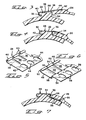
- Figure 3 shows the structure of rib 22 and clasp 28 in section.
- the rib is undercut on one side to provide an overhang 32.
- the opposite side 34 of the rib is straight.
- Side 26 is thicker to accommodate the clasp and to provide a face 36 of substantially the same thickness as rib 22.
- FIG. 5 shows clasp 28 in perspective. It is an elongated member preferably stamped and formed from a coplanar strip of metal (not shown) such as steel. Other metals and other materials having sufficient rigidity would be suitable also. Fingers 38 are defined along one side by slotting. The free ends of the fingers are formed around into C-shaped hooks 40. The remaining width, hereinafter referred to as strap 42 of the clasp, contains spaced holes 44.
- the section drawing shows that strap 42 is embedded in side 26 with the material filling holes 44 to anchor the strap.
- the strap is positioned near the upper surface of that side.
- the sides of wrap 16 are latched together by catching hooks 40 onto overhang 32. This requires angling side 26 as illustrated in Figure 3. With the hooks caught, the side 26 is brought down so that face 36 abuts side 34 of the rib straight on. The two sides are latched together as shown in Figure 4 and cannot come apart under the linear pull that the latched sides will see during recovery. However, the sides may be unlatched prior to recovery simply by pulling side 26 upwardly to clear rib side 34 and then pushing forwardly so that hooks 40 can clear overhang 32.
- FIG. 6 is a perspective view of another embodiment of a clasp.
- This clasp indicated by reference numeral 46, has a plurality of fingers 48 on one side with the free ends formed into C-shaped hooks 50.
- the slots defining the fingers are confined within the clasp material so that each hook is connected to the adjacent hook by a strip of material indicated by reference numeral 52.
- Strap 54 contains spaced holes 56. However, in this embodiment, the strap is offset vertically from the fingers by bend 58.
- Clasp 46 is embedded in side 26 near the lower surface so that bend 58 covers face 36 and abuts side 34 when the two sides are latched together as shown in Figure 7.
Landscapes
- Engineering & Computer Science (AREA)
- General Engineering & Computer Science (AREA)
- Physics & Mathematics (AREA)
- Mechanical Engineering (AREA)
- General Physics & Mathematics (AREA)
- Optics & Photonics (AREA)
- Insulating Bodies (AREA)
- Cable Accessories (AREA)
- Clamps And Clips (AREA)
Applications Claiming Priority (2)
| Application Number | Priority Date | Filing Date | Title |
|---|---|---|---|
| US264739 | 1981-05-18 | ||
| US06/264,739 US4517234A (en) | 1981-05-18 | 1981-05-18 | Heat recoverable sleeve forming wrap |
Publications (2)
| Publication Number | Publication Date |
|---|---|
| EP0065383A1 true EP0065383A1 (de) | 1982-11-24 |
| EP0065383B1 EP0065383B1 (de) | 1985-04-17 |
Family
ID=23007402
Family Applications (1)
| Application Number | Title | Priority Date | Filing Date |
|---|---|---|---|
| EP82302304A Expired EP0065383B1 (de) | 1981-05-18 | 1982-05-06 | Wärmerückstellbare Hülle zur Bildung einer Muffe |
Country Status (5)
| Country | Link |
|---|---|
| US (1) | US4517234A (de) |
| EP (1) | EP0065383B1 (de) |
| AU (1) | AU552265B2 (de) |
| CA (1) | CA1180525A (de) |
| DE (1) | DE3263088D1 (de) |
Cited By (1)
| Publication number | Priority date | Publication date | Assignee | Title |
|---|---|---|---|---|
| EP0112698A1 (de) * | 1982-12-17 | 1984-07-04 | N.V. Raychem S.A. | Wickelbare Muffe |
Families Citing this family (15)
| Publication number | Priority date | Publication date | Assignee | Title |
|---|---|---|---|---|
| US4756337A (en) * | 1986-02-24 | 1988-07-12 | Royston Laboratories, Inc. | Gasline repair kit |
| FI87010C (fi) * | 1986-03-26 | 1992-11-10 | Raychem Sa Nv | Anordning och saett att taecka ett foeremaol |
| US4961978A (en) * | 1989-03-06 | 1990-10-09 | The Kendall Company | Novel closure device for shrinkwraps |
| JPH1089545A (ja) * | 1996-09-18 | 1998-04-10 | Toosetsu Kk | 防火区画貫通部材 |
| US5722463A (en) * | 1996-11-25 | 1998-03-03 | Petro-Line Upgrading Services Ltd. | External pipe reinforcing sleeve |
| IT1286516B1 (it) * | 1996-12-02 | 1998-07-15 | Montell North America Inc | Procedimento per la riparazione dei rivestimenti in materiali plastici di tubi metallici |
| JP3808594B2 (ja) * | 1997-06-26 | 2006-08-16 | カルソニックカンセイ株式会社 | パイプ |
| GB0010970D0 (en) * | 2000-05-05 | 2000-06-28 | Tyco Electronics Raychem Gmbh | Cable enclosure |
| US6520215B2 (en) * | 2001-02-27 | 2003-02-18 | Hayes-Albion Corporation | Tubular bar with integral rolled locking system and method of making same |
| JP3949396B2 (ja) * | 2001-06-12 | 2007-07-25 | 矢崎総業株式会社 | コルゲートチューブ |
| JP3883398B2 (ja) * | 2001-06-12 | 2007-02-21 | 矢崎総業株式会社 | コルゲートチューブ及びその形成方法 |
| AU2005269849B2 (en) | 2004-07-08 | 2009-10-08 | Knoll, Inc. | Office chair |
| DE202006012464U1 (de) * | 2006-08-12 | 2007-12-27 | Rehau Ag + Co. | Abdeckungsvorrichtung |
| US8796549B2 (en) * | 2011-02-02 | 2014-08-05 | Tyco Electronics Corporation | Wire bushing |
| US12487147B2 (en) * | 2023-03-23 | 2025-12-02 | Saudi Arabian Oil Company | Composite wrap for pipe monitoring and repair |
Citations (6)
| Publication number | Priority date | Publication date | Assignee | Title |
|---|---|---|---|---|
| US3455336A (en) * | 1965-11-03 | 1969-07-15 | Raychem Corp | Heat recoverable article and process |
| GB1261122A (en) * | 1969-09-16 | 1972-01-19 | Walter A Plummer | Electrically shielded heat-reactive jacket for conductors |
| DE2909979A1 (de) * | 1979-03-14 | 1980-09-18 | Siegfried Mueller | Vorrichtung zum abdichten von verbindungsstellen an einem durchlaufenden gegenstand, insbesondere von kabelmuffen |
| GB2054781A (en) * | 1979-07-27 | 1981-02-18 | Egerton A C Ltd | Material for wrapping around a pipe, cable or the like |
| GB2061025A (en) * | 1979-07-27 | 1981-05-07 | Egerton Eng Bromley Ltd A C | Material for wrapping around pipe, cable or the like |
| EP0036250A1 (de) * | 1980-02-23 | 1981-09-23 | Raychem Limited | Umhüllvorrichtung und eine solche Vorrichtung umfassende Anordnung |
Family Cites Families (16)
| Publication number | Priority date | Publication date | Assignee | Title |
|---|---|---|---|---|
| US1015919A (en) * | 1911-02-11 | 1912-01-30 | Henry R Wardell | Bituminous structural material. |
| US2665869A (en) * | 1948-03-12 | 1954-01-12 | Refiector Hardware Corp | Hanger and spacer bracket |
| GB918313A (en) * | 1959-11-19 | 1963-02-13 | Jakobsen Kjell | Improvements in or relating to a method of excavating rock, ore and the like by blasting, and means for use in said method |
| US3091487A (en) * | 1960-04-14 | 1963-05-28 | William H Gallagher | Clip |
| US3112542A (en) * | 1961-05-01 | 1963-12-03 | Ward L Brunson | Bag clip |
| US3379218A (en) * | 1965-07-29 | 1968-04-23 | Raychem Corp | Closure sleeve for pipes or the like |
| CH480588A (de) * | 1968-04-05 | 1969-10-31 | Dynamit Nobel Ag | Profil aus thermoplastischem Kunststoff |
| US3542077A (en) * | 1968-05-22 | 1970-11-24 | Raychem Corp | Differentially cross-linked article and process for making the same |
| US3574313A (en) * | 1968-10-30 | 1971-04-13 | Raychem Corp | Wraparound closure sleeve |
| US3847721A (en) * | 1971-04-02 | 1974-11-12 | Raychem Corp | Heat recoverable articles and methods therefor |
| US4123047A (en) * | 1976-12-15 | 1978-10-31 | Raychem Corporation | Modular clip assembly for heat shrinkable material |
| GB1604440A (en) * | 1977-12-23 | 1981-12-09 | Raychem Sa Nv | Heatrecoverable wrap-around devices |
| US4378393A (en) * | 1978-09-22 | 1983-03-29 | High Voltage Engineering Corporation | Heat-shrinkable article |
| ES263042Y (es) * | 1979-07-27 | 1983-04-16 | Material destinado a ser enrollado alrededor de un tubo,un cable o elemento parecido. | |
| DE2939241C2 (de) * | 1979-09-27 | 1982-04-22 | Siemens AG, 1000 Berlin und 8000 München | Verschlußvorrichtung bei Kabelgarnituren aus wärmeschrumpfbarem Material |
| DE2951329C2 (de) * | 1979-12-20 | 1982-11-11 | Brokmann, Manfred, Ing. (Grad.) | Gurt, insbesondere Bespannungsgurt für Möbel |
-
1981
- 1981-05-18 US US06/264,739 patent/US4517234A/en not_active Expired - Fee Related
-
1982
- 1982-04-22 AU AU82921/82A patent/AU552265B2/en not_active Ceased
- 1982-04-28 CA CA000401796A patent/CA1180525A/en not_active Expired
- 1982-05-06 EP EP82302304A patent/EP0065383B1/de not_active Expired
- 1982-05-06 DE DE8282302304T patent/DE3263088D1/de not_active Expired
Patent Citations (6)
| Publication number | Priority date | Publication date | Assignee | Title |
|---|---|---|---|---|
| US3455336A (en) * | 1965-11-03 | 1969-07-15 | Raychem Corp | Heat recoverable article and process |
| GB1261122A (en) * | 1969-09-16 | 1972-01-19 | Walter A Plummer | Electrically shielded heat-reactive jacket for conductors |
| DE2909979A1 (de) * | 1979-03-14 | 1980-09-18 | Siegfried Mueller | Vorrichtung zum abdichten von verbindungsstellen an einem durchlaufenden gegenstand, insbesondere von kabelmuffen |
| GB2054781A (en) * | 1979-07-27 | 1981-02-18 | Egerton A C Ltd | Material for wrapping around a pipe, cable or the like |
| GB2061025A (en) * | 1979-07-27 | 1981-05-07 | Egerton Eng Bromley Ltd A C | Material for wrapping around pipe, cable or the like |
| EP0036250A1 (de) * | 1980-02-23 | 1981-09-23 | Raychem Limited | Umhüllvorrichtung und eine solche Vorrichtung umfassende Anordnung |
Cited By (1)
| Publication number | Priority date | Publication date | Assignee | Title |
|---|---|---|---|---|
| EP0112698A1 (de) * | 1982-12-17 | 1984-07-04 | N.V. Raychem S.A. | Wickelbare Muffe |
Also Published As
| Publication number | Publication date |
|---|---|
| AU8292182A (en) | 1982-11-25 |
| AU552265B2 (en) | 1986-05-29 |
| DE3263088D1 (en) | 1985-05-23 |
| US4517234A (en) | 1985-05-14 |
| CA1180525A (en) | 1985-01-08 |
| EP0065383B1 (de) | 1985-04-17 |
Similar Documents
| Publication | Publication Date | Title |
|---|---|---|
| EP0065383B1 (de) | Wärmerückstellbare Hülle zur Bildung einer Muffe | |
| EP0023418B1 (de) | Hülle zum Umwickeln einer Rohrleitung, eines Kabels oder dgl. | |
| EP0133337B1 (de) | Hitzeschrumpfmanschette | |
| EP0223424A1 (de) | Verschluss für eine wickelbare Muffe | |
| EP0938159A1 (de) | Eine wasserdichte Konstruction für Kabelende und Verfahren zur Herstellung einer wasserdichten Konstruction | |
| US5488760A (en) | Inner lock band clamp | |
| DE3317445A1 (de) | Schutzring fuer ueberlandleitungen | |
| EP0971845A1 (de) | Kabelbinder | |
| JPH0150069B2 (de) | ||
| NO823040L (no) | Gjenvinnbart lukke | |
| EP0087227A1 (de) | Umgriffhülse | |
| JPH0345869B2 (de) | ||
| US5129608A (en) | Snap fit clamp | |
| EP3909102B1 (de) | Polsterhülse | |
| EP0431035B1 (de) | Erneuter zugang und verschluss eines kabelspleissgehäuses | |
| GB2054781A (en) | Material for wrapping around a pipe, cable or the like | |
| EP0034500A1 (de) | Verschlussvorrichtung für eine rückstellfähige, einen Gegenstand umgreifende Hülse | |
| US4364419A (en) | Heat-recoverable wraparound closure | |
| CN1152203A (zh) | 一种底物的紧密包封装置 | |
| CA1051987A (en) | Heat recoverable closure assembly and method | |
| GB2061025A (en) | Material for wrapping around pipe, cable or the like | |
| EP0094242A2 (de) | Vorrichtung und Verfahren zum Abdichten | |
| US2746107A (en) | Pressure clamps | |
| JP2002354622A (ja) | ケーブル保護用パイプの引き込み方法 | |
| AU741918B2 (en) | Fastener and band |
Legal Events
| Date | Code | Title | Description |
|---|---|---|---|
| PUAI | Public reference made under article 153(3) epc to a published international application that has entered the european phase |
Free format text: ORIGINAL CODE: 0009012 |
|
| AK | Designated contracting states |
Designated state(s): BE DE FR GB IT NL |
|
| 17P | Request for examination filed |
Effective date: 19830126 |
|
| ITF | It: translation for a ep patent filed | ||
| GRAA | (expected) grant |
Free format text: ORIGINAL CODE: 0009210 |
|
| AK | Designated contracting states |
Designated state(s): BE DE FR GB IT NL |
|
| REF | Corresponds to: |
Ref document number: 3263088 Country of ref document: DE Date of ref document: 19850523 |
|
| ET | Fr: translation filed | ||
| PLBE | No opposition filed within time limit |
Free format text: ORIGINAL CODE: 0009261 |
|
| STAA | Information on the status of an ep patent application or granted ep patent |
Free format text: STATUS: NO OPPOSITION FILED WITHIN TIME LIMIT |
|
| 26N | No opposition filed | ||
| ITTA | It: last paid annual fee | ||
| PGFP | Annual fee paid to national office [announced via postgrant information from national office to epo] |
Ref country code: FR Payment date: 19940407 Year of fee payment: 13 |
|
| PGFP | Annual fee paid to national office [announced via postgrant information from national office to epo] |
Ref country code: GB Payment date: 19940419 Year of fee payment: 13 |
|
| PGFP | Annual fee paid to national office [announced via postgrant information from national office to epo] |
Ref country code: DE Payment date: 19940420 Year of fee payment: 13 |
|
| PGFP | Annual fee paid to national office [announced via postgrant information from national office to epo] |
Ref country code: BE Payment date: 19940428 Year of fee payment: 13 |
|
| REG | Reference to a national code |
Ref country code: GB Ref legal event code: 732E |
|
| PG25 | Lapsed in a contracting state [announced via postgrant information from national office to epo] |
Ref country code: GB Effective date: 19950506 |
|
| PG25 | Lapsed in a contracting state [announced via postgrant information from national office to epo] |
Ref country code: BE Effective date: 19950531 |
|
| BERE | Be: lapsed |
Owner name: AMP INC. (UNE SOC. DE PENNSYLVANIE) Effective date: 19950531 |
|
| GBPC | Gb: european patent ceased through non-payment of renewal fee |
Effective date: 19950506 |
|
| PG25 | Lapsed in a contracting state [announced via postgrant information from national office to epo] |
Ref country code: DE Effective date: 19960201 |
|
| PG25 | Lapsed in a contracting state [announced via postgrant information from national office to epo] |
Ref country code: FR Effective date: 19960229 |
|
| PGFP | Annual fee paid to national office [announced via postgrant information from national office to epo] |
Ref country code: NL Payment date: 19960328 Year of fee payment: 15 |
|
| REG | Reference to a national code |
Ref country code: FR Ref legal event code: ST |
|
| REG | Reference to a national code |
Ref country code: FR Ref legal event code: ST |
|
| PG25 | Lapsed in a contracting state [announced via postgrant information from national office to epo] |
Ref country code: NL Effective date: 19971201 |
|
| NLV4 | Nl: lapsed or anulled due to non-payment of the annual fee |
Effective date: 19971201 |