EP0065405A2 - Torche utile dans des procédés à arc à électrode en carbone dans l'air - Google Patents
Torche utile dans des procédés à arc à électrode en carbone dans l'air Download PDFInfo
- Publication number
- EP0065405A2 EP0065405A2 EP82302385A EP82302385A EP0065405A2 EP 0065405 A2 EP0065405 A2 EP 0065405A2 EP 82302385 A EP82302385 A EP 82302385A EP 82302385 A EP82302385 A EP 82302385A EP 0065405 A2 EP0065405 A2 EP 0065405A2
- Authority
- EP
- European Patent Office
- Prior art keywords
- electrode
- torch
- gas
- injector
- air
- Prior art date
- Legal status (The legal status is an assumption and is not a legal conclusion. Google has not performed a legal analysis and makes no representation as to the accuracy of the status listed.)
- Withdrawn
Links
Images

Classifications
-
- B—PERFORMING OPERATIONS; TRANSPORTING
- B23—MACHINE TOOLS; METAL-WORKING NOT OTHERWISE PROVIDED FOR
- B23K—SOLDERING OR UNSOLDERING; WELDING; CLADDING OR PLATING BY SOLDERING OR WELDING; CUTTING BY APPLYING HEAT LOCALLY, e.g. FLAME CUTTING; WORKING BY LASER BEAM
- B23K7/00—Cutting, scarfing, or desurfacing by applying flames
- B23K7/10—Auxiliary devices, e.g. for guiding or supporting the torch
-
- B—PERFORMING OPERATIONS; TRANSPORTING
- B23—MACHINE TOOLS; METAL-WORKING NOT OTHERWISE PROVIDED FOR
- B23K—SOLDERING OR UNSOLDERING; WELDING; CLADDING OR PLATING BY SOLDERING OR WELDING; CUTTING BY APPLYING HEAT LOCALLY, e.g. FLAME CUTTING; WORKING BY LASER BEAM
- B23K9/00—Arc welding or cutting
- B23K9/24—Features related to electrodes
- B23K9/28—Supporting devices for electrodes
- B23K9/285—Cooled electrode holders
Definitions
- This invention relates to a torch useful particularly but not exclusively in air-carbon arc processes.
- One such process for removing metal involves striking an arc between a carbon electrode and the workpiece. This forms a pool of molten metal which is blown from the workpiece surface by air jets directed along the length of the electrode. The air jets also tend to cool the electrode. The process can remove metal at very high rates and is used widely throughout the steel foundry industry. Unfortunately, there is much noise, heat, and fume. Because the air jets do not cool sufficiently,. the electrode is at a very high temperature and it tends to break down very rapidly. For this reason the electrode constitutes a high proportion of the cost of the operation.
- One object of the invention is to provide an improved torch for the purpose specified and which reduces or avoids the disadvantages outlined above.
- a torch comprising an elongate electrode in a holder therefor and means for providing a stream of gas at least at the tip of the electrode, in which gas control means is arranged to provide a substantially annular flow of gas along the electrode.
- the gas control means is preferably a venturi-like injector located about part of the length of the electrode.
- the venturi-type air injector may be separately applied to the electrode but it is preferred that the venturi-type air injector is combined with an electrode holder arranged so that the electrode will be concentric with the injector. While the internal shape of the gas control means may be a divergent or convergent bore, it is preferred that the inner walls of the means be substantially parallel.
- any suitable gas may be passed along the electrode to cool it; in practice it will usually be air with an appropriate air supply connected to an inlet of a venturi type air injector.
- compressed air is emitted through an-annular gap positioned relative to the throat of the venturi so as to induce an air flow through volume the injector.
- the / flow rate of the induced air flow is many times greater than that of the compressed air alone, and will be-maintained as a coherent stream to the tip of the electrode. Air velocities and hence noise levels will be less than those experienced on a conventional torch but total mass flow rate of induced + driven air is much higher.
- the metal removal rates and the ability to cool the electrode are increased resulting in more efficient electrode usage.
- the torch is hand held and for this the torch includes a handle.
- the supply of gas to the gas control means and along the electrode is located in the handle; this serves to cool the handle and lighten the overall weight of the tool.
- the torch is arranged such that the handle incorporates an electrode clamp which is movable through 180° relative to the rest of the torch making it easier to angle the electrode relative to a workpiece.
- the invention further includes a method of striking an arc between a carbon electrode and a workpiece and including providing a stream of gas at least at the tip of the electrode, in which, according to the invention, the stream of gas is a substantially annular flow along the electrode.
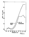
- a torch of this invention has proved to be much quieter in use than a known torch, probably because the high frequency components of the air noise are reduced.
- a torch of this invention uses compressed air at the same pressure as a known torch but the rate of consumption is far less.
- the rate of removing metal from a workpiece is improved compared with a known torch: increases of up to 25% in terms of grams metal removed per unit time have been achieved and similar improvements have been obtained in electrode consumption at the usual rate of metal removal.
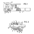
- the torch of Figures 1 and 2 includes a handle 1.
- the head of the handle is connected to a coupling 2 which engages an index plate 3.
- the plate 3 is connected to the inlet side or throat of a venturi air injector 4 of generally known type.
- the injector comprises an outer annulus 5 and an inner annulus 6, with a small enclosed chamber 7 inbetween; the inner annulus 6 may be moved longitudinally with respect to the outer 5 by a screw thread "8 to adjust the gap in between.
- a first clamp half 9 for the electrode E e.g.
- a carbon electrode has a shank 10 which passes through the index plate 3 and the head of the handle 1; a second clamp half 11 is mounted on the end of a cranked handle 12 pivotally mounted on the first handle 1.
- the clamp halves 9, 11 are urged towards each other under the bias of a strong spring 13 between the handles 1, 12.
- the index plate 3 includes two grooves, not shown, arranged at right angles to each other.
- the grooves are of different depths and the clamp half 9 can be rotated with respect to the plate 3 so that two different electrode diameters can be positioned in the clamp half and concentric with the air injector 4.
- the handle 1 has an air passageway 14 which communicates with another 15 in the coupling 2 and a third 16 in the index plate 3.
- the passageway 16 defines a small annular gap close to the throat of the injector 4 so directing compressed air into the injector 4.
- Electrical wiring 17 extends along the handle 1 via the coupling 2 to the clamp halves 9, 11.
- the coupling 2 and the index plate 3 are electrically insulated.
- an electrode E is held between the clamp halves 9, 11 and in this way is positioned concentric with respect to the injector 4.
- Compressed air is fed along the handle 1 in the passageway 14 and via the passageways 15, 16 into the throat of the injector 4.
- an additional air flow Fi is induced through the rear of the injector 4 and the total air of compressed and induced air flows as a coherent stream along the length of the electrode E to the tip Et.
- An arc is struck between the tip Et and a workpiece, not shown, and the pool of metal is blown off by the total air flow.
- the total air flow cools the electrode along its length and also the clamp halves Which tend to get hot as very high electrical currents are often used. There is little noise, fume or metal splatter; the rate of consumption of electrode and compressed air are reduced.
Landscapes
- Engineering & Computer Science (AREA)
- Mechanical Engineering (AREA)
- Physics & Mathematics (AREA)
- Plasma & Fusion (AREA)
- Arc Welding In General (AREA)
- Medicines Containing Material From Animals Or Micro-Organisms (AREA)
- Carbon And Carbon Compounds (AREA)
Applications Claiming Priority (9)
| Application Number | Priority Date | Filing Date | Title |
|---|---|---|---|
| GB8114635 | 1981-05-13 | ||
| GB8114635 | 1981-05-13 | ||
| NO823747A NO823747L (no) | 1981-05-13 | 1982-11-10 | Lysbue for karbon-luft-bueprosesser |
| ZA828292A ZA828292B (en) | 1981-05-13 | 1982-11-11 | Torch useful in air-carbon processes |
| AU90500/82A AU9050082A (en) | 1981-05-13 | 1982-11-16 | Arc welding torch |
| PT75873A PT75873B (en) | 1981-05-13 | 1982-11-19 | Improved torch useful in air-carbon arc processes |
| JP57205329A JPS5994588A (ja) | 1981-05-13 | 1982-11-22 | 空気カ−ボン・ア−ク法で用いるト−チ |
| ES517566A ES517566A0 (es) | 1981-05-13 | 1982-11-22 | Perfeccionamientos en sopletes generadores de arco entre un electrodo de carbon y una pieza de trabajo. |
| BR8206766A BR8206766A (pt) | 1981-05-13 | 1982-11-23 | Macarico e processo para formar arco entre eletrodo de carbono e peca de trabalho |
Publications (2)
| Publication Number | Publication Date |
|---|---|
| EP0065405A2 true EP0065405A2 (fr) | 1982-11-24 |
| EP0065405A3 EP0065405A3 (fr) | 1983-08-03 |
Family
ID=27570116
Family Applications (1)
| Application Number | Title | Priority Date | Filing Date |
|---|---|---|---|
| EP82302385A Withdrawn EP0065405A3 (fr) | 1981-05-13 | 1982-05-11 | Torche utile dans des procédés à arc à électrode en carbone dans l'air |
Country Status (10)
| Country | Link |
|---|---|
| US (1) | US4464555A (fr) |
| EP (1) | EP0065405A3 (fr) |
| JP (1) | JPS5994588A (fr) |
| KR (1) | KR840002278A (fr) |
| AU (1) | AU9050082A (fr) |
| BR (1) | BR8206766A (fr) |
| ES (1) | ES517566A0 (fr) |
| NO (1) | NO823747L (fr) |
| PT (1) | PT75873B (fr) |
| ZA (1) | ZA828292B (fr) |
Families Citing this family (8)
| Publication number | Priority date | Publication date | Assignee | Title |
|---|---|---|---|---|
| US4571478A (en) * | 1983-04-21 | 1986-02-18 | Air Products And Chemicals, Inc. | Electrode drive and nozzle system for an automatic air carbon-arc cutting and gouging torch |
| US4527037A (en) * | 1983-04-21 | 1985-07-02 | Arcair Company | Electrode drive and nozzle system for an automatic air carbon-arc cutting and gouging torch |
| US4721837A (en) * | 1985-09-25 | 1988-01-26 | Eutectic Corporation | Cored tubular electrode and method for the electric-arc cutting of metals |
| US4973809A (en) * | 1986-11-03 | 1990-11-27 | Jenkins Henry H | Cutting and gouging electrode |
| ITUA20162979A1 (it) * | 2016-04-28 | 2017-10-28 | Illinois Tool Works | Teste per placcatura a nastro aventi limiti di pressione del nastro e sistemi di placcatura a nastro con teste per placcatura a nastro aventi limiti di pressione del nastro |
| ITUA20162983A1 (it) | 2016-04-28 | 2017-10-28 | Illinois Tool Works | Teste per placcatura a nastro aventi regolazioni indipendenti della pressione del nastro e sistemi di placcatura a nastro con teste per placcatura a nastro aventi regolazioni indipendenti della pressione del nastro |
| ITUA20162977A1 (it) | 2016-04-28 | 2017-10-28 | Illinois Tool Works | Alimentatori di nastro per placcatura aventi supporti di guida regolabili per il nastro e sistemi di placcatura a nastro con alimentatori di nastro per placcatura aventi supporti di guida regolabili per il nastro |
| JP6284599B1 (ja) * | 2016-09-14 | 2018-02-28 | 本田技研工業株式会社 | 電極チップ取付装置 |
Family Cites Families (6)
| Publication number | Priority date | Publication date | Assignee | Title |
|---|---|---|---|---|
| BE481981A (fr) * | ||||
| DE1039675B (de) * | 1957-07-20 | 1958-09-25 | Agil Schweissdraht Dr Vaas G M | Schutzgas-Lichtbogenschweissverfahren mit Kohlendioxyd im inneren Ringstrom und mit einem aeusseren Ringstrom |
| US3113201A (en) * | 1959-10-23 | 1963-12-03 | Myron D Stepath | Electric arc cutting and gouging tool |
| US3624339A (en) * | 1969-09-30 | 1971-11-30 | Henry H Jenkins | Electric arc-type cutting gun |
| US4300033A (en) * | 1979-06-14 | 1981-11-10 | Rensselaer Polytechnic Institute | Reduced operating noise nozzle for electric arc cutting device |
| US4315126A (en) * | 1980-05-29 | 1982-02-09 | Union Carbide Corporation | Method of air cutting and gouging and a combined torch and nozzle assembly |
-
1982
- 1982-05-11 EP EP82302385A patent/EP0065405A3/fr not_active Withdrawn
- 1982-05-11 US US06/377,218 patent/US4464555A/en not_active Expired - Fee Related
- 1982-11-10 NO NO823747A patent/NO823747L/no unknown
- 1982-11-11 ZA ZA828292A patent/ZA828292B/xx unknown
- 1982-11-16 AU AU90500/82A patent/AU9050082A/en not_active Abandoned
- 1982-11-19 PT PT75873A patent/PT75873B/pt unknown
- 1982-11-22 JP JP57205329A patent/JPS5994588A/ja active Pending
- 1982-11-22 ES ES517566A patent/ES517566A0/es active Granted
- 1982-11-22 KR KR1019820005261A patent/KR840002278A/ko not_active Ceased
- 1982-11-23 BR BR8206766A patent/BR8206766A/pt unknown
Also Published As
| Publication number | Publication date |
|---|---|
| BR8206766A (pt) | 1984-06-26 |
| JPS5994588A (ja) | 1984-05-31 |
| ES8403348A1 (es) | 1984-03-16 |
| US4464555A (en) | 1984-08-07 |
| PT75873A (en) | 1982-12-01 |
| AU9050082A (en) | 1984-05-24 |
| ZA828292B (en) | 1983-09-28 |
| PT75873B (en) | 1985-12-09 |
| NO823747L (no) | 1984-05-11 |
| ES517566A0 (es) | 1984-03-16 |
| KR840002278A (ko) | 1984-06-25 |
| EP0065405A3 (fr) | 1983-08-03 |
Similar Documents
| Publication | Publication Date | Title |
|---|---|---|
| CA2174019C (fr) | Torche pour soudage plasma avec buse d'injection d'eau | |
| US5944915A (en) | Cutting nozzle assembly for a postmixed oxy- fuel gas torch | |
| US3597576A (en) | Spatter and heat shield for welding gun | |
| US4464555A (en) | Torch, useful in air-carbon arc processes | |
| US3050616A (en) | Arc process and apparatus | |
| JPS61255767A (ja) | プラズマア−クト−チ用コンポ−ネントノズル | |
| EP0705656B1 (fr) | Insert pour une méthode et appareillage pour ébavurage | |
| US4493970A (en) | Slag and fume collector for air carbon-arc cutting and gouging torches | |
| US6277323B1 (en) | Cutting nozzle assembly for a postmixed oxy-fuel gas torch | |
| US6096992A (en) | Low current water injection nozzle and associated method | |
| US3659072A (en) | Cutting and gouging electrode holder | |
| US4300033A (en) | Reduced operating noise nozzle for electric arc cutting device | |
| US3033133A (en) | Powder washing apparatus | |
| EP1324644A3 (fr) | Dispositif de découpe par plasma d'arc | |
| US2538916A (en) | Gas torch | |
| US2536201A (en) | Thermochemical metal removal method and apparatus | |
| US4166209A (en) | Apparatus for reducing operating noise of the air-carbon arc cutting and gouging process | |
| US2491440A (en) | Apparatus for flame-cutting metal | |
| SE444475B (sv) | Handverktyg for gassvetsning och -skerning | |
| US4315126A (en) | Method of air cutting and gouging and a combined torch and nozzle assembly | |
| US2260322A (en) | Deseaming and desurfacing apparatus and process | |
| US2538074A (en) | Scarfing apparatus | |
| US2735796A (en) | Process for thermochemically washing | |
| US4258244A (en) | Method for reducing operating noise of the air-carbon arc cutting and gouging process | |
| US4303118A (en) | Apparatus for producing aluminum-deoxidized continuously cast steel |
Legal Events
| Date | Code | Title | Description |
|---|---|---|---|
| PUAI | Public reference made under article 153(3) epc to a published international application that has entered the european phase |
Free format text: ORIGINAL CODE: 0009012 |
|
| AK | Designated contracting states |
Designated state(s): AT BE CH DE FR GB IT LI NL SE |
|
| RBV | Designated contracting states (corrected) |
Designated state(s): AT BE CH DE FR GB IT LI NL SE |
|
| PUAL | Search report despatched |
Free format text: ORIGINAL CODE: 0009013 |
|
| AK | Designated contracting states |
Designated state(s): AT BE CH DE FR GB IT LI NL SE |
|
| 17P | Request for examination filed |
Effective date: 19840202 |
|
| STAA | Information on the status of an ep patent application or granted ep patent |
Free format text: STATUS: THE APPLICATION HAS BEEN WITHDRAWN |
|
| 18W | Application withdrawn |
Withdrawal date: 19851114 |
|
| RIN1 | Information on inventor provided before grant (corrected) |
Inventor name: WALLIS, ROGER |