EP0065453A1 - Metallrohrwand-Wärmetauscher - Google Patents
Metallrohrwand-Wärmetauscher Download PDFInfo
- Publication number
- EP0065453A1 EP0065453A1 EP82400825A EP82400825A EP0065453A1 EP 0065453 A1 EP0065453 A1 EP 0065453A1 EP 82400825 A EP82400825 A EP 82400825A EP 82400825 A EP82400825 A EP 82400825A EP 0065453 A1 EP0065453 A1 EP 0065453A1
- Authority
- EP
- European Patent Office
- Prior art keywords
- tubes
- exchanger
- fluid
- exchanger according
- heat
- Prior art date
- Legal status (The legal status is an assumption and is not a legal conclusion. Google has not performed a legal analysis and makes no representation as to the accuracy of the status listed.)
- Granted
Links
Images



Classifications
-
- F—MECHANICAL ENGINEERING; LIGHTING; HEATING; WEAPONS; BLASTING
- F28—HEAT EXCHANGE IN GENERAL
- F28F—DETAILS OF HEAT-EXCHANGE AND HEAT-TRANSFER APPARATUS, OF GENERAL APPLICATION
- F28F13/00—Arrangements for modifying heat-transfer, e.g. increasing, decreasing
-
- B—PERFORMING OPERATIONS; TRANSPORTING
- B23—MACHINE TOOLS; METAL-WORKING NOT OTHERWISE PROVIDED FOR
- B23K—SOLDERING OR UNSOLDERING; WELDING; CLADDING OR PLATING BY SOLDERING OR WELDING; CUTTING BY APPLYING HEAT LOCALLY, e.g. FLAME CUTTING; WORKING BY LASER BEAM
- B23K28/00—Welding or cutting not covered by groups B23K5/00 - B23K26/00
-
- F—MECHANICAL ENGINEERING; LIGHTING; HEATING; WEAPONS; BLASTING
- F25—REFRIGERATION OR COOLING; COMBINED HEATING AND REFRIGERATION SYSTEMS; HEAT PUMP SYSTEMS; MANUFACTURE OR STORAGE OF ICE; LIQUEFACTION SOLIDIFICATION OF GASES
- F25D—REFRIGERATORS; COLD ROOMS; ICE-BOXES; COOLING OR FREEZING APPARATUS NOT OTHERWISE PROVIDED FOR
- F25D17/00—Arrangements for circulating cooling fluids; Arrangements for circulating gas, e.g. air, within refrigerated spaces
- F25D17/02—Arrangements for circulating cooling fluids; Arrangements for circulating gas, e.g. air, within refrigerated spaces for circulating liquids, e.g. brine
-
- F—MECHANICAL ENGINEERING; LIGHTING; HEATING; WEAPONS; BLASTING
- F28—HEAT EXCHANGE IN GENERAL
- F28D—HEAT-EXCHANGE APPARATUS, NOT PROVIDED FOR IN ANOTHER SUBCLASS, IN WHICH THE HEAT-EXCHANGE MEDIA DO NOT COME INTO DIRECT CONTACT
- F28D3/00—Heat-exchange apparatus having stationary conduit assemblies for one heat-exchange medium only, the media being in contact with different sides of the conduit wall, in which the other heat-exchange medium flows in a continuous film, or trickles freely, over the conduits
- F28D3/02—Heat-exchange apparatus having stationary conduit assemblies for one heat-exchange medium only, the media being in contact with different sides of the conduit wall, in which the other heat-exchange medium flows in a continuous film, or trickles freely, over the conduits with tubular conduits
-
- F—MECHANICAL ENGINEERING; LIGHTING; HEATING; WEAPONS; BLASTING
- F28—HEAT EXCHANGE IN GENERAL
- F28F—DETAILS OF HEAT-EXCHANGE AND HEAT-TRANSFER APPARATUS, OF GENERAL APPLICATION
- F28F1/00—Tubular elements; Assemblies of tubular elements
- F28F1/02—Tubular elements of cross-section which is non-circular
- F28F1/04—Tubular elements of cross-section which is non-circular polygonal, e.g. rectangular
-
- F—MECHANICAL ENGINEERING; LIGHTING; HEATING; WEAPONS; BLASTING
- F28—HEAT EXCHANGE IN GENERAL
- F28F—DETAILS OF HEAT-EXCHANGE AND HEAT-TRANSFER APPARATUS, OF GENERAL APPLICATION
- F28F1/00—Tubular elements; Assemblies of tubular elements
- F28F1/10—Tubular elements and assemblies thereof with means for increasing heat-transfer area, e.g. with fins, with projections, with recesses
- F28F1/12—Tubular elements and assemblies thereof with means for increasing heat-transfer area, e.g. with fins, with projections, with recesses the means being only outside the tubular element
- F28F1/14—Tubular elements and assemblies thereof with means for increasing heat-transfer area, e.g. with fins, with projections, with recesses the means being only outside the tubular element and extending longitudinally
- F28F1/22—Tubular elements and assemblies thereof with means for increasing heat-transfer area, e.g. with fins, with projections, with recesses the means being only outside the tubular element and extending longitudinally the means having portions engaging further tubular elements
-
- F—MECHANICAL ENGINEERING; LIGHTING; HEATING; WEAPONS; BLASTING
- F28—HEAT EXCHANGE IN GENERAL
- F28F—DETAILS OF HEAT-EXCHANGE AND HEAT-TRANSFER APPARATUS, OF GENERAL APPLICATION
- F28F19/00—Preventing the formation of deposits or corrosion, e.g. by using filters or scrapers
- F28F19/02—Preventing the formation of deposits or corrosion, e.g. by using filters or scrapers by using coatings, e.g. vitreous or enamel coatings
- F28F19/06—Preventing the formation of deposits or corrosion, e.g. by using filters or scrapers by using coatings, e.g. vitreous or enamel coatings of metal
Definitions
- the present invention relates to a heat exchanger delimited by two parallel surfaces intended to be placed in a substantially vertical position during use, comprising a bundle of parallel metal tubes connected so as to constitute a circuit for a first fluid and nested in the less with a bundle of elongated metal members in thermal contact with the tubes and with a second fluid to form a sheet, the fluids being able to circulate in single phase (liquid or gas) or to change phase there.
- the elongated members may in particular be constituted by tubes belonging to a circuit for the second fluid or by fins in thermal contact with an ambient fluid, such as the atmosphere. These exchangers generally use cylindrical tubes. When seeking to obtain high heat transfers, they are formed or coated with a good conductive material, such as copper or aluminum.
- the present invention aims to provide an exchanger which meets the requirements of practice better than those known in the past, in particular in that it makes it possible to produce heat exchangers which, at the same time, have a moderate cost, have a coefficient of high exchange and allow heat exchanges between three fluids.
- the invention proposes in particular an exchanger of the kind defined above, the tubes of which are of rectangular section (advantageously square) and in contact with the adjacent elongated members, including second tubes also having a rectangular section, by all surface of the opposite faces of said tubes and which is intended for heat transfers between the two fluids and an additional fluid circulating around the exchanger.
- the exchanger thus has a monolayer constitution, each first tube having two free opposite faces and two surfaces in contact with the adjacent tubes.
- the tubes are advantageously made of steel, protected on their four faces against corrosions of external origin and thermally connected with the adjacent elongated members by hot galvanizing.
- This galvanization fulfills several distinct functions: the life of the exchanger is considerably increased, including when the exchanger is exposed to atmospheric agents, to such an extent that a ten-year guarantee is possible. Due to the high thermal conductivity of zinc (double that of iron), the coefficient of heat exchange between the tubes and the elongated members becomes very satisfactory.
- a material other than steel in particular a metal capable of being shaped by press spinning (aluminum and light alloys for example).
- the invention finds a particularly important, although not exclusive, application in hot water supply installations comprising a thermodynamic circuit traversed by a refrigerant (fluid B) and the cold source of which comprises a solar exchanger.
- the heat exchanger according to the invention can in this case be used in particular as an exchanger-evaporator, in which case the second tubes are traversed by the refrigerant, whereas the first tubes are traversed by the fluid which cannot be solidified from the cold source (fluid A).
- the exchanger can be used as an atmospheric exchanger, the members being able to comprise profiled fins, having surfaces of the same width as the tubes, intended to be applied on these tubes.
- An exchanger according to the invention is particularly advantageous as an evaporator in an installation of the type described in patent application EP-A-0042795.
- ice can form on the surfaces of a heat exchanger, the latent heat of this ice being supplied to a thermodynamic circuit.
- the exchanger includes a circuit traversed by an unfrozen heat transfer fluid (fluid A) coming either from solar exchangers, or from a capacity containing hot fluid intended to take off the ice. You can run water on the exchanger to take off the ice.
- the exchanger comprises a flat sheet comprising metal tubes 10 alternated with elongated members.
- these elongated members are constituted by tubes 11a_ identical to the tubes 10.
- these elongated members also comprise profiled fins 11b of the same width as the tubes.
- the tubes are made of steel, rectangular in shape, and treated by hot-dip galvanizing.
- This treatment can in particular successively comprise a degreasing, a pickling with hydrochloric acid at 50%, a double rinsing, a treatment by a flux consisting of a double salt of ammonium and zinc, preheating to approximately 110 ° C and immersion in a tank of molten zinc to approximately 450 ° C.
- the rinsing and fluxing operations are specially resumed with a pressurized jet so as to remove any trace of acid and penetrate to the right of the interstices between the tubes.
- circuits constituted by continuous tubes can withstand a very high pressure, of the order of 50 bars, without damage, and that the constitution of the heat exchanger in two separate sealed bundles ensures great safety when one of the fluids used is corrosive or reacts violently when in contact with the other fluid. This provision is imposed in the case of a domestic installation.
- the elongated members comprise a set of fins in profiled or folded sheet metal, the cross section of which is in the shape of M.
- the steel of the fins is covered by a layer obtained by hot galvanizing, layer which improves the heat transfers between fins 11b and tubes 10 and lia.
- a sheet of the kind shown in FIG. 3 can be connected to a high collector 12 and a low collector 13 into which the tubes 10 open in parallel.
- the pipes intake 14 and exhaust 15 collectors can be connected in series or in parallel until constituting the required exchange surface.
- Such a heat exchanger can in particular be used as an atmospheric sensor in a hot water supply installation of the type described in patent application EP 0042795.
- An exchanger with two bundles of tubes can be used to constitute the evaporator exchanger of a thermodynamic circuit installation of the type described and claimed in patent application No. EP 0042795 already mentioned.
- Such an evaporator exchanger is particularly advantageous in the case of an installation of the type shown in FIG. 3 of the above-mentioned prior application, installation constituting an ice factory when the supply of solar energy to the exchanger constituting the cold source becomes insufficient. .
- FIG. 4 shows the diagram of an exchanger-evaporator usable in such an installation, with planar geometry.
- the tubes 10 are connected in series-parallel to form the vaporizable thermodynamic fluid B circuit (fluorinated fluid such as that designated by the mark "FREON” in general) in the exchanger.
- the tubes 11a are mounted between two collectors 15 and 16 to constitute a circuit for the circulation of water added with an antifreeze such as glycol (fluid A). This circuit will close via the cold source which can be a solar collector or an atmospheric sensor.
- the exchanger is completed by a hot melt water supply circuit.
- ice (fluid D). In the case of an assembly of the type illustrated in FIGS. 5 to 8, this fluid D enters through a tube 33 in a dead tube lower stiffener 31 (FIG. 6), travels against the current in the tubes 10 and exits through a tube. 18 ( Figures 4 and 5 a).
- the exchanger is associated with a runoff ramp 19 placed above, supplied by the tube 17, by a lifting pump not shown and allowing water to be poured onto the tubes which turns into ice there. by providing heat in the form of heat latent solidification when the temperature of the atmospheric cold source is particularly low.
- the collector 16 constitutes a partitioned water box at 20 while the collector 15 re-coils all the outgoing tubes 10 onto all the return tubes 10.
- the tubes 11a of the refrigerant circuit are identical to the tubes 10 and, by way of example, a tube 10 has been shown for each tube 11a.
- the "pins" for the circulation of the refrigerant (fluid B) may not include all the successive tubes. In the general case of m pins each comprising n tubes 11a, there must be (m + 1) n tubes 11a and (m + 1) n + 1 tubes 10.
- the placing in series of the branches of the same pin intended for the fluid Refrigerant is ensured by 180 ° bending of the tubes, the elbow being placed obliquely to the general plane of the beam to allow the passage of the tubes 10 joining their water box.
- the entire beam can be linked and stiffened by folded sheet metal strips, spot welded to the tubes.
- the take-off water circulation circuit can use dead tubes or stiffening tubes.
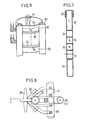
- FIG. 9-11 show a cylindrical arrangement, which is particularly advantageous for constituting modules with a unit power of less than 60 kW (individual houses).
- the exchanger is then constituted by a cylindrical device made up of two nested propellers; contiguous formed one by a tube 10, the other by a tube 11a. These propellers are joined along one side of the square or rectangular tube and all of the tubes are thermally bonded by specially treated hot-dip galvanization.
- a runoff circuit and an ice takeoff circuit similar to those of FIG. 5 are provided.
- the internal and external fins are designed and constructed so that the ice falls vertically during the icebreaking cycles.
- an apparatus of the type shown in FIG. 9 can be constituted for a unit power of 4 kw having a diameter of 70 cm and a height of approximately 50 cm.
- the exchanger shown having a thermal power of 6 kW, has a refrigerant circuit (B) and a water circuit with antifreeze (A) made up of 16 mm square tubes, hot dip galvanized.
- the mechanical rigidity of the exchanger is ensured by stiffeners 25 and connection profiles 26 fixed to each other by welding points such as 27. Some of the tubes connecting the exchanger with the rest of the installation can be threaded to allow the unit to be suspended.
- the tubes 10 and 11a are joined to the profiles 26 by welding points.
- the elbows 22 connecting the outward and return branches of the pins traversed by the refrigerant are angularly offset from the plane of the tubes.
- the evaporator exchanger being intended for an installation of the "ice-making" type described in application EP 00'42795, is completed by a gutter 32 for trickling water drawn from the water reserve, entering the pipe. inlet 17, and by a diffuser 30. The latter distributes the water over the walls of the exchanger in a substantially uniform manner for the purpose of forming of ice.
- dead tubes 31 are provided either to constitute the ice take-off water circuit, or to constitute zones of the exchanger on which there is no formation of ice.
Landscapes
- Engineering & Computer Science (AREA)
- Physics & Mathematics (AREA)
- Mechanical Engineering (AREA)
- Thermal Sciences (AREA)
- General Engineering & Computer Science (AREA)
- Geometry (AREA)
- Chemical & Material Sciences (AREA)
- Combustion & Propulsion (AREA)
- Heat-Exchange Devices With Radiators And Conduit Assemblies (AREA)
Applications Claiming Priority (2)
| Application Number | Priority Date | Filing Date | Title |
|---|---|---|---|
| FR8108846A FR2505474B1 (fr) | 1981-05-05 | 1981-05-05 | Echangeur de chaleur a nappe de tubes metalliques |
| FR8108846 | 1981-05-05 |
Publications (2)
| Publication Number | Publication Date |
|---|---|
| EP0065453A1 true EP0065453A1 (de) | 1982-11-24 |
| EP0065453B1 EP0065453B1 (de) | 1985-02-20 |
Family
ID=9258050
Family Applications (1)
| Application Number | Title | Priority Date | Filing Date |
|---|---|---|---|
| EP19820400825 Expired EP0065453B1 (de) | 1981-05-05 | 1982-05-05 | Metallrohrwand-Wärmetauscher |
Country Status (3)
| Country | Link |
|---|---|
| EP (1) | EP0065453B1 (de) |
| DE (1) | DE3262391D1 (de) |
| FR (1) | FR2505474B1 (de) |
Citations (16)
| Publication number | Priority date | Publication date | Assignee | Title |
|---|---|---|---|---|
| DE183101C (de) * | ||||
| GB299100A (en) * | 1927-04-22 | 1928-10-22 | Francis Grimshaw Martin | Improvements in heat exchange apparatus comprising tubes having an electrolytic deposit of metal on the interior thereof |
| CH182808A (de) * | 1935-06-05 | 1936-02-29 | Regard Francis | Kühlvorrichtung. |
| FR866806A (fr) * | 1939-05-27 | 1941-09-08 | Sulzer Ag | Réfrigérant pour liquides, fonctionnant avec dépôts de glace |
| DE827655C (de) * | 1950-10-12 | 1952-01-10 | Holstein & Kappert Maschf | Flaechen-Berieselungskuehler |
| US2997861A (en) * | 1958-10-17 | 1961-08-29 | Vilter Manufacturing Corp | Art of producing ice briquettes |
| GB886194A (en) * | 1958-09-22 | 1962-01-03 | Warrington Tube Company Ltd | Improvements relating to flat units for emitting or absorbing heat |
| US3285334A (en) * | 1961-12-11 | 1966-11-15 | Peerless Of America | Integral dual-passage heat exchange tubing with reverse bends |
| FR1573193A (de) * | 1968-04-17 | 1969-07-04 | ||
| US3727681A (en) * | 1971-06-17 | 1973-04-17 | United Aircraft Prod | Cartridge type tube and fin heat exchanger |
| DE2649872A1 (de) * | 1976-10-29 | 1978-05-11 | Ortner Harald | Waermepumpe zur erzeugung von nutzwaerme und nutzkaelte mit energiespeicherung unter ausnutzung der erstarrungs- bzw. schmelzwaerme von wasser |
| US4101287A (en) * | 1977-01-21 | 1978-07-18 | Exxon Research & Engineering Co. | Combined heat exchanger reactor |
| FR2407448A1 (fr) * | 1977-11-01 | 1979-05-25 | Borg Warner | Surface de transfert de chaleur, procede de preparation de cette surface et procede d'ebullition |
| EP0010817A1 (de) * | 1978-11-06 | 1980-05-14 | Akzo N.V. | Aus Kanälen mit kleinem Durchmesser gebildetes Wärmeaustauschgerät und seine Verwendung in verschiedenen Heizungssystemen |
| FR2439954A2 (fr) * | 1978-10-27 | 1980-05-23 | Chapelle Jacques | Dispositif de stockage thermique a basse temperature par gel de l'eau |
| DE2921908A1 (de) * | 1979-05-30 | 1980-12-11 | Weiss | Waermetauscher |
-
1981
- 1981-05-05 FR FR8108846A patent/FR2505474B1/fr not_active Expired
-
1982
- 1982-05-05 EP EP19820400825 patent/EP0065453B1/de not_active Expired
- 1982-05-05 DE DE8282400825T patent/DE3262391D1/de not_active Expired
Patent Citations (16)
| Publication number | Priority date | Publication date | Assignee | Title |
|---|---|---|---|---|
| DE183101C (de) * | ||||
| GB299100A (en) * | 1927-04-22 | 1928-10-22 | Francis Grimshaw Martin | Improvements in heat exchange apparatus comprising tubes having an electrolytic deposit of metal on the interior thereof |
| CH182808A (de) * | 1935-06-05 | 1936-02-29 | Regard Francis | Kühlvorrichtung. |
| FR866806A (fr) * | 1939-05-27 | 1941-09-08 | Sulzer Ag | Réfrigérant pour liquides, fonctionnant avec dépôts de glace |
| DE827655C (de) * | 1950-10-12 | 1952-01-10 | Holstein & Kappert Maschf | Flaechen-Berieselungskuehler |
| GB886194A (en) * | 1958-09-22 | 1962-01-03 | Warrington Tube Company Ltd | Improvements relating to flat units for emitting or absorbing heat |
| US2997861A (en) * | 1958-10-17 | 1961-08-29 | Vilter Manufacturing Corp | Art of producing ice briquettes |
| US3285334A (en) * | 1961-12-11 | 1966-11-15 | Peerless Of America | Integral dual-passage heat exchange tubing with reverse bends |
| FR1573193A (de) * | 1968-04-17 | 1969-07-04 | ||
| US3727681A (en) * | 1971-06-17 | 1973-04-17 | United Aircraft Prod | Cartridge type tube and fin heat exchanger |
| DE2649872A1 (de) * | 1976-10-29 | 1978-05-11 | Ortner Harald | Waermepumpe zur erzeugung von nutzwaerme und nutzkaelte mit energiespeicherung unter ausnutzung der erstarrungs- bzw. schmelzwaerme von wasser |
| US4101287A (en) * | 1977-01-21 | 1978-07-18 | Exxon Research & Engineering Co. | Combined heat exchanger reactor |
| FR2407448A1 (fr) * | 1977-11-01 | 1979-05-25 | Borg Warner | Surface de transfert de chaleur, procede de preparation de cette surface et procede d'ebullition |
| FR2439954A2 (fr) * | 1978-10-27 | 1980-05-23 | Chapelle Jacques | Dispositif de stockage thermique a basse temperature par gel de l'eau |
| EP0010817A1 (de) * | 1978-11-06 | 1980-05-14 | Akzo N.V. | Aus Kanälen mit kleinem Durchmesser gebildetes Wärmeaustauschgerät und seine Verwendung in verschiedenen Heizungssystemen |
| DE2921908A1 (de) * | 1979-05-30 | 1980-12-11 | Weiss | Waermetauscher |
Also Published As
| Publication number | Publication date |
|---|---|
| EP0065453B1 (de) | 1985-02-20 |
| FR2505474A1 (fr) | 1982-11-12 |
| FR2505474B1 (fr) | 1986-01-03 |
| DE3262391D1 (en) | 1985-03-28 |
Similar Documents
| Publication | Publication Date | Title |
|---|---|---|
| EP0119502B1 (de) | Thermoelektrische Anlage | |
| EP4019878B1 (de) | Thermisches speichermodul aus phasenwechselmaterial, dessen herstellung vereinfacht ist | |
| SK400990A3 (en) | Method of making a heat exchanger | |
| EP4212814B1 (de) | Modulare wärmespeicheranordnung mit phasenwechselmaterial, dessen herstellung vereinfachten herstellung | |
| EP2577181A1 (de) | Modul für einen wärmeabsorber eines solarempfänger mit mindestens einem derartigen modul und empfänger mit mindestens einem derartigen absorber | |
| FR2809484A1 (fr) | Bloc echangeur de chaleur | |
| WO2017001558A1 (fr) | Dispositif de stockage d'énergie par matériau à changement de phase et son procédé de stockage | |
| EP0065453B1 (de) | Metallrohrwand-Wärmetauscher | |
| EP2623909B1 (de) | Fotovoltaikpaneel mit Wärmerückgewinnung | |
| FR2533307A1 (fr) | Procede pour chauffer par induction des pieces a une temperature uniforme, notamment pour fabriquer des radiateurs de vehicule automobile | |
| EP2783978A1 (de) | Schwebende Struktur mit eine thermodynamische Maschine mit eine optimiert energetische Leistung | |
| WO2003046456A1 (fr) | Profils de tube pour echangeur thermique | |
| FR2533154A1 (fr) | Procede pour braser par induction un assemblage complexe, et en particulier, un echangeur de chaleur | |
| WO2013017677A2 (fr) | Module photovoltaïque avec échangeur thermique | |
| RU2043885C1 (ru) | Способ изготовления теплообменника | |
| EP3214398B1 (de) | Einrichtung zur energiespeicherung mit phasenwechselmaterial einschliesslich elektrische ladung integriert in dem flüssigkeitskreislauf | |
| FR3043187B1 (fr) | Batterie thermique a chaleur latente pour automobile | |
| FR2548769A1 (fr) | Installation de chauffage a pompes a chaleur et a capteurs d'energie atmospherique | |
| BE1006617A3 (fr) | Tubes a ailettes et procede pour leur fabrication. | |
| FR2955380A1 (fr) | Systeme solaire thermique et procede pour chauffer un espace habitable | |
| FR2481422A1 (fr) | Procede et installation de production et de distribution de chaleur a l'interieur des locaux d'un immeuble | |
| US20100018521A1 (en) | Solar collector with foil absorber | |
| FR2657954A1 (fr) | Dispositif d'echange thermique a plaques planes et a turbulateurs. | |
| FR2776371A1 (fr) | Echangeur de chaleur a enveloppe externe en tube plastique | |
| FR2463372A1 (fr) | Dispositif thermoelectrique a transfert de chaleur entre un premier fluide liquide et un deuxieme fluide |
Legal Events
| Date | Code | Title | Description |
|---|---|---|---|
| PUAI | Public reference made under article 153(3) epc to a published international application that has entered the european phase |
Free format text: ORIGINAL CODE: 0009012 |
|
| AK | Designated contracting states |
Designated state(s): BE CH DE FR GB IT NL SE |
|
| 17P | Request for examination filed |
Effective date: 19830112 |
|
| ITF | It: translation for a ep patent filed | ||
| GRAA | (expected) grant |
Free format text: ORIGINAL CODE: 0009210 |
|
| AK | Designated contracting states |
Designated state(s): BE CH DE FR GB IT LI NL SE |
|
| REF | Corresponds to: |
Ref document number: 3262391 Country of ref document: DE Date of ref document: 19850328 |
|
| PLBE | No opposition filed within time limit |
Free format text: ORIGINAL CODE: 0009261 |
|
| STAA | Information on the status of an ep patent application or granted ep patent |
Free format text: STATUS: NO OPPOSITION FILED WITHIN TIME LIMIT |
|
| 26N | No opposition filed | ||
| PGFP | Annual fee paid to national office [announced via postgrant information from national office to epo] |
Ref country code: FR Payment date: 19910424 Year of fee payment: 10 |
|
| PGFP | Annual fee paid to national office [announced via postgrant information from national office to epo] |
Ref country code: GB Payment date: 19910430 Year of fee payment: 10 |
|
| PGFP | Annual fee paid to national office [announced via postgrant information from national office to epo] |
Ref country code: CH Payment date: 19910521 Year of fee payment: 10 |
|
| PGFP | Annual fee paid to national office [announced via postgrant information from national office to epo] |
Ref country code: SE Payment date: 19910524 Year of fee payment: 10 |
|
| ITTA | It: last paid annual fee | ||
| PGFP | Annual fee paid to national office [announced via postgrant information from national office to epo] |
Ref country code: NL Payment date: 19910531 Year of fee payment: 10 |
|
| PGFP | Annual fee paid to national office [announced via postgrant information from national office to epo] |
Ref country code: BE Payment date: 19910613 Year of fee payment: 10 |
|
| PGFP | Annual fee paid to national office [announced via postgrant information from national office to epo] |
Ref country code: DE Payment date: 19910715 Year of fee payment: 10 |
|
| PG25 | Lapsed in a contracting state [announced via postgrant information from national office to epo] |
Ref country code: GB Effective date: 19920505 |
|
| PG25 | Lapsed in a contracting state [announced via postgrant information from national office to epo] |
Ref country code: SE Effective date: 19920506 |
|
| PG25 | Lapsed in a contracting state [announced via postgrant information from national office to epo] |
Ref country code: LI Effective date: 19920531 Ref country code: CH Effective date: 19920531 Ref country code: BE Effective date: 19920531 |
|
| BERE | Be: lapsed |
Owner name: CHARLES ROBERT Effective date: 19920531 Owner name: ELECTRICITE DE FRANCE SERVICE NATIONAL Effective date: 19920531 |
|
| PG25 | Lapsed in a contracting state [announced via postgrant information from national office to epo] |
Ref country code: NL Effective date: 19921201 |
|
| GBPC | Gb: european patent ceased through non-payment of renewal fee |
Effective date: 19920505 |
|
| NLV4 | Nl: lapsed or anulled due to non-payment of the annual fee | ||
| PG25 | Lapsed in a contracting state [announced via postgrant information from national office to epo] |
Ref country code: FR Effective date: 19930129 |
|
| REG | Reference to a national code |
Ref country code: CH Ref legal event code: PL |
|
| PG25 | Lapsed in a contracting state [announced via postgrant information from national office to epo] |
Ref country code: DE Effective date: 19930202 |
|
| REG | Reference to a national code |
Ref country code: FR Ref legal event code: ST |
|
| EUG | Se: european patent has lapsed |
Ref document number: 82400825.4 Effective date: 19921204 |