EP0065496A2 - Drehwerkzeug für das Schnellschnittbearbeiten von Holz, Kunststoffen oder Leichtmetallen - Google Patents
Drehwerkzeug für das Schnellschnittbearbeiten von Holz, Kunststoffen oder Leichtmetallen Download PDFInfo
- Publication number
- EP0065496A2 EP0065496A2 EP82830097A EP82830097A EP0065496A2 EP 0065496 A2 EP0065496 A2 EP 0065496A2 EP 82830097 A EP82830097 A EP 82830097A EP 82830097 A EP82830097 A EP 82830097A EP 0065496 A2 EP0065496 A2 EP 0065496A2
- Authority
- EP
- European Patent Office
- Prior art keywords
- clamping body
- rotating tools
- fact
- resisting block
- inserts
- Prior art date
- Legal status (The legal status is an assumption and is not a legal conclusion. Google has not performed a legal analysis and makes no representation as to the accuracy of the status listed.)
- Granted
Links
Images
Classifications
-
- B—PERFORMING OPERATIONS; TRANSPORTING
- B27—WORKING OR PRESERVING WOOD OR SIMILAR MATERIAL; NAILING OR STAPLING MACHINES IN GENERAL
- B27G—ACCESSORY MACHINES OR APPARATUS FOR WORKING WOOD OR SIMILAR MATERIALS; TOOLS FOR WORKING WOOD OR SIMILAR MATERIALS; SAFETY DEVICES FOR WOOD WORKING MACHINES OR TOOLS
- B27G13/00—Cutter blocks; Other rotary cutting tools
- B27G13/08—Cutter blocks; Other rotary cutting tools in the shape of disc-like members; Wood-milling cutters
- B27G13/10—Securing the cutters, e.g. by clamping collars
Definitions
- This invention concerns means to clamp inserts in rotat- . ing tools.
- this invention concerns means to clamp. inserts in rotating tools which are employed advantageously. for the processing of wood or plastics, or, in any case, in tools which rotate at high speed.
- Clumping means have to be provided which align and secure the insert automatically.
- a housing space which has the shape substantially of a truncated cone and which widens towards the middle of the tool holder.
- a suitable seating space for the tool At the side of the housing space is envisaged a suitable seating space for the tool, and said seating is dimensioned and positioned perfectly in relation to the middler of the tool itself so that, when said seating supports the tool or- insert, said tool or insert is located perfectly in relation to the middle of the tool holder and therefore in relation to the plurality of other tools or inserts.
- the clar- mping body has two clamping surfaces that cooperate with resisting blocks on which a regulating screw having a righthand thread and a lefthand thread acts.
- resisting blocks By turning the screw said resisting blocks can be brought nearer to or farther from each other.
- the regulating screw comprises in an intermediate position a ring which provides lengthwise anchorage and which can cooperate with an anchorage hollow that may possibly be included in the clamping body.
- Substitute means can also be visualised.
- Said anchorage ring can cooperate with a safety pin which holds the regulating screw onto the clamping body and which can exert at the same time on the clamping body an outwards thrust that constrains said clamping body to be embedded in the housing space.
- the anchorage ring has an intermediate hollow within which the safety pin is made to pass.
- the opposing surfaces are- not linear but have a substantially rounded development so - as to reduce to a minimum the necessity for accurate mating This makes it possible to maintain at the same time a thrust strong enough to obtain an almost irreversible clamping condition when the forces in question are taken into account.
- the area of contact between the resisting block and the opposing wall may possibly be suitably shaped.
- the resisting block cooperates with a screw located in an almost radial position and acting on both the recisting block and the clamping body at the same time.
- the resisting block comprises a slit such that the walls of the block itself are made elastic.
- the invention is therefore embodied in means to clamp inserts in rotating tools, and advantageously in rotating tools employed in the processing of wood, plastics or light metals, whereby said rotating tools travel at a very high speed and- the inserts can be re-used and readily replaced, said clamping means being characterised by the fact that in the tool .
- a holder there is envisaged a plurality of housing spaces which have the shape substantially of a truncated cone and which - widen towards the middle of the tool holder, whereby a seating for a tool is positioned at the side of said housing space and a clamping body is located in said housing space and cooperates with at least one resisting block, and whereby at least the resisting block cooperates with a regulating screw able to exert on said resisting block and on said clamping - body a lateral thrust such as will constrain said resisting- block against the opposing wall of said housing space and will constrain said clamping body against the insert and substantially towards the middle of the tool holder.
- the table contains the following:-
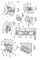
- Said seating I4 for a tool includes a supporting corner 15 and a wall 16 supporting an insert.
- the conformation of the housing II substantially like a truncated cone has the effect that, as the wall I6 support- - ing the insert 23 is substantially parallel to a plane passing through the axis of the toolrholder I0, the opposing
- a clamping body 17 is introduced within the housing II and., in the example of Fig.I, comprises a lengthwise hollow 32 in which are located two resisting blocks 18-118 cooperating with a regulating screw 19 having a righthand and a lefthand thread.
- Said regulating screw 19 includes a ring 20 for lengthwise anchorage, and said ring 20 cooperates with a hollow 21 for- lengthwise anchorage formed in the clamping body 17.
- Opposing surfaces 22 are provided in the lengthwise hol- ⁇ low 32 of the clamping body 17 and cooperate with respective resisting surfaces 122 formed on the resisting blocks 18.
- the resisting blocks 38 are, for instance, drawn towards each other and the respective resisting surfaces 122 press on the opposing surfaces 22 of the clamping body 17.
- the position of the opposing wall 12 conditions the char- .acteristics of the movement of the clamping body 17.
- Said tool 23 comprises one or more holes 24 which cooper- .ate with appropriate pins 25 solidly fixed to the clamping body 17.
- the clamping body 17 is advantageously envisaged as comprising a protective outlet 26 which cooperates with the cut- .ting edge of the insert 23 lying against the supporting corner 15.
- Said safety pin 27 can be single, as in Fig.I, or double, as in Fig.3, or can have other suitable shapes according to. the requirements of the design.
- the ring 20 providing lengthwise anchorage and comprised in the regulating screw 19 can have. an intermediate hollow 28 within which the safety pin 27 is. made to lodge; in this way the hollow 21 providing lengthwise anchorage is rendered substantially useless.
- the embodiment now shown entails a movement substantially parallel to the axis of rotation of the tool holder 10.
- the resisting block 218 is thrust towards the opposing wall 12 by screw means II9, which. also have a righthand and a lefthand thread and which engage the resisting block 218 and the clamping body II7 at one and the same time.
- clamping body II7 is thrust not only towards the supporting wall 13 but also towards the insert 23. and constrains said insert 23 to rest against the supporting corner 15.
- the twofold inclination permits safer and more . longlasting anchorage in the long term even when there are - vibrations.
- the resisting block 318 comprises a hollow which enables the two sides A & B of the block itself to bend in relation to each other, whereby the side B is able to lodge the head 30 of the screw 230, whereas the side A can lodge the threaded part 130 thereof.
- the opposing surfaces 22-I22 are rounded or crovm-shaped; it can be envisaged that the .sliding surfaces 31 between the body 218 and body 217 may .possibly have a special shape, and so forth.
Landscapes
- Life Sciences & Earth Sciences (AREA)
- Engineering & Computer Science (AREA)
- Mechanical Engineering (AREA)
- Wood Science & Technology (AREA)
- Forests & Forestry (AREA)
- Clamps And Clips (AREA)
- Automatic Tool Replacement In Machine Tools (AREA)
- Specific Conveyance Elements (AREA)
- Toys (AREA)
- Debarking, Splitting, And Disintegration Of Timber (AREA)
- Hand Tools For Fitting Together And Separating, Or Other Hand Tools (AREA)
- Perforating, Stamping-Out Or Severing By Means Other Than Cutting (AREA)
- Crushing And Pulverization Processes (AREA)
- Turning (AREA)
- Supports Or Holders For Household Use (AREA)
- Mechanical Pencils And Projecting And Retracting Systems Therefor, And Multi-System Writing Instruments (AREA)
Priority Applications (1)
| Application Number | Priority Date | Filing Date | Title |
|---|---|---|---|
| AT82830097T ATE18367T1 (de) | 1981-05-11 | 1982-04-19 | Drehwerkzeug fuer das schnellschnittbearbeiten von holz, kunststoffen oder leichtmetallen. |
Applications Claiming Priority (2)
| Application Number | Priority Date | Filing Date | Title |
|---|---|---|---|
| IT83378/81A IT1147492B (it) | 1981-05-11 | 1981-05-11 | Mezzi di bloccaggio degli inserti negli utensili rotanti |
| IT8337881 | 1981-05-11 |
Publications (3)
| Publication Number | Publication Date |
|---|---|
| EP0065496A2 true EP0065496A2 (de) | 1982-11-24 |
| EP0065496A3 EP0065496A3 (en) | 1983-05-04 |
| EP0065496B1 EP0065496B1 (de) | 1986-03-05 |
Family
ID=11320991
Family Applications (1)
| Application Number | Title | Priority Date | Filing Date |
|---|---|---|---|
| EP82830097A Expired EP0065496B1 (de) | 1981-05-11 | 1982-04-19 | Drehwerkzeug für das Schnellschnittbearbeiten von Holz, Kunststoffen oder Leichtmetallen |
Country Status (6)
| Country | Link |
|---|---|
| EP (1) | EP0065496B1 (de) |
| AT (1) | ATE18367T1 (de) |
| DE (1) | DE3269560D1 (de) |
| ES (1) | ES274453Y (de) |
| IT (1) | IT1147492B (de) |
| PT (1) | PT74867B (de) |
Cited By (6)
| Publication number | Priority date | Publication date | Assignee | Title |
|---|---|---|---|---|
| FR2564028A1 (fr) * | 1984-05-10 | 1985-11-15 | Fontaine Bernard | Dispositif de fixation des lames interchangeables sur porte-outil de machines a bois |
| EP0152125A3 (de) * | 1984-02-08 | 1986-06-11 | STARK S.p.A. | Drehendes Werkzeug mit Schneidplatten |
| DE3636618A1 (de) * | 1986-10-28 | 1988-05-05 | Babcock Bsh Ag | Messerwelle |
| DE8906720U1 (de) * | 1989-05-11 | 1990-10-04 | A. Oppold GmbH & Co. KG, 7082 Oberkochen | Messerkopf mit wenigstens einem Messer od.dgl., das an einer Spannfläche in einer Ausnehmung des Werkzeugträgers anliegt |
| FR2744659A1 (fr) * | 1996-02-08 | 1997-08-14 | Bridonneau Ets | Systeme de fixation d'une plaquette sur un outil de coupe rotatif |
| AT2192U1 (de) * | 1997-07-22 | 1998-06-25 | Aigner Werkzeuge Ges M B H | Messerkopf für eine fräsvorrichtung |
Family Cites Families (12)
| Publication number | Priority date | Publication date | Assignee | Title |
|---|---|---|---|---|
| DE229751C (de) * | ||||
| DE366560C (de) * | 1919-02-15 | 1923-01-06 | Karl Boellert | Messerbefestigung an Messerwellen und Messerkoepfen zur Holzbearbeitung |
| US1527650A (en) * | 1922-10-26 | 1925-02-24 | James B Hunt | Rotary cutting tool |
| GB393669A (en) * | 1931-12-15 | 1933-06-15 | Philip Harris | Improvements relating to wood-working machines |
| DE617874C (de) * | 1935-11-20 | 1936-09-05 | Maschb Leya A G | Vorrichtung zum Halten der Messer in der Messerwelle fuer Hobelmaschinen |
| DE918710C (de) * | 1949-07-26 | 1954-10-04 | Josef Abele | Schlitz-Fraesscheibe fuer Holzbearbeitung |
| DE839556C (de) * | 1950-06-29 | 1952-05-23 | Boettcher & Gessner | Hobelmesserwelle fuer Holzbearbeitung mit Keileinspannung |
| DE858602C (de) * | 1951-07-05 | 1952-12-08 | Heinrich Gensheimer & Soehne M | Sicherheitsmesserwelle |
| DE1111368B (de) * | 1958-03-21 | 1961-07-20 | Rohde & Doerrenberg | Messerbefestigung mittels Keilwirkung in Zerspannungswerkzeugen mit auswechselbaren Messern |
| GB890427A (en) * | 1959-09-22 | 1962-02-28 | Womersley & Broadbent Ltd | Rotary cutter blocks for the working of wood, metal and other suitable materials |
| DE7602409U1 (de) * | 1976-01-29 | 1976-12-09 | Ledermann + Co, 7240 Horb | Einbauhalter fuer ein schneidwerkzeug |
| DE2917079A1 (de) * | 1979-04-27 | 1980-10-30 | Kloeckner Gmbh & Co Geb | Messerbefestigung an zerkleinerungsmaschinen mit umlaufenden schneidmessern |
-
1981
- 1981-05-11 IT IT83378/81A patent/IT1147492B/it active
-
1982
- 1982-04-19 AT AT82830097T patent/ATE18367T1/de not_active IP Right Cessation
- 1982-04-19 DE DE8282830097T patent/DE3269560D1/de not_active Expired
- 1982-04-19 EP EP82830097A patent/EP0065496B1/de not_active Expired
- 1982-05-10 ES ES1982274453U patent/ES274453Y/es not_active Expired
- 1982-05-10 PT PT74867A patent/PT74867B/pt unknown
Cited By (6)
| Publication number | Priority date | Publication date | Assignee | Title |
|---|---|---|---|---|
| EP0152125A3 (de) * | 1984-02-08 | 1986-06-11 | STARK S.p.A. | Drehendes Werkzeug mit Schneidplatten |
| FR2564028A1 (fr) * | 1984-05-10 | 1985-11-15 | Fontaine Bernard | Dispositif de fixation des lames interchangeables sur porte-outil de machines a bois |
| DE3636618A1 (de) * | 1986-10-28 | 1988-05-05 | Babcock Bsh Ag | Messerwelle |
| DE8906720U1 (de) * | 1989-05-11 | 1990-10-04 | A. Oppold GmbH & Co. KG, 7082 Oberkochen | Messerkopf mit wenigstens einem Messer od.dgl., das an einer Spannfläche in einer Ausnehmung des Werkzeugträgers anliegt |
| FR2744659A1 (fr) * | 1996-02-08 | 1997-08-14 | Bridonneau Ets | Systeme de fixation d'une plaquette sur un outil de coupe rotatif |
| AT2192U1 (de) * | 1997-07-22 | 1998-06-25 | Aigner Werkzeuge Ges M B H | Messerkopf für eine fräsvorrichtung |
Also Published As
| Publication number | Publication date |
|---|---|
| PT74867A (en) | 1982-06-01 |
| ES274453Y (es) | 1985-04-01 |
| EP0065496B1 (de) | 1986-03-05 |
| EP0065496A3 (en) | 1983-05-04 |
| DE3269560D1 (en) | 1986-04-10 |
| ES274453U (es) | 1984-10-01 |
| IT8183378A0 (it) | 1981-05-11 |
| ATE18367T1 (de) | 1986-03-15 |
| PT74867B (en) | 1983-11-22 |
| IT1147492B (it) | 1986-11-19 |
Similar Documents
| Publication | Publication Date | Title |
|---|---|---|
| US4443136A (en) | Machine cutting tool | |
| US3662444A (en) | Indexable cutting insert and holder therefor | |
| US4552491A (en) | Cutting tool having cylindrical ceramic insert | |
| US3831237A (en) | Mounting apparatus for indexable cutting inserts | |
| US4334446A (en) | Cutting tool and holder therefor | |
| RU2221674C2 (ru) | Режущая пластина для вращающихся режущих инструментов | |
| SU1222189A3 (ru) | Однорезцова развертка | |
| JPH012813A (ja) | カッター・ヘッド | |
| HK110596A (en) | Tool with adjustable interchangeable cartridge | |
| US6413021B1 (en) | Rotating cutting tool | |
| EP0065496A2 (de) | Drehwerkzeug für das Schnellschnittbearbeiten von Holz, Kunststoffen oder Leichtmetallen | |
| US3616507A (en) | Milling cutter | |
| US6176648B1 (en) | Face milling cutter and cutter body thereof | |
| US4525109A (en) | Cutting tool having a cutting blade in a shank slot | |
| JP3337215B2 (ja) | 切削機械加工用工具 | |
| US2958119A (en) | Cutting tool | |
| US3815195A (en) | Arrangement for locating cutting insert in holder | |
| EP0096669A1 (de) | Fräser mit auswechselbaren Schneideinsätzen | |
| US5197231A (en) | Rotary cutter having expanded cutting ring | |
| US3584361A (en) | Milling head | |
| US3915585A (en) | Boring bar and an elongated boring bar insert having boring tools at opposite ends | |
| US5345846A (en) | Tool holder with resharpenable form tool insert | |
| US2149038A (en) | Tool holder | |
| EP0109719B1 (de) | Werkzeughalter mit Werkzeug | |
| EP0406184B1 (de) | Dynamisch eingespanntes Hobelwerkzeug und Verfahren zu seiner Herstellung |
Legal Events
| Date | Code | Title | Description |
|---|---|---|---|
| PUAI | Public reference made under article 153(3) epc to a published international application that has entered the european phase |
Free format text: ORIGINAL CODE: 0009012 |
|
| AK | Designated contracting states |
Designated state(s): AT BE CH DE FR GB LI LU NL SE |
|
| PUAL | Search report despatched |
Free format text: ORIGINAL CODE: 0009013 |
|
| RHK1 | Main classification (correction) |
Ipc: B27G 13/04 |
|
| AK | Designated contracting states |
Designated state(s): AT BE CH DE FR GB LI LU NL SE |
|
| 17P | Request for examination filed |
Effective date: 19830418 |
|
| GRAA | (expected) grant |
Free format text: ORIGINAL CODE: 0009210 |
|
| AK | Designated contracting states |
Kind code of ref document: B1 Designated state(s): AT BE CH DE FR GB LI LU NL SE |
|
| REF | Corresponds to: |
Ref document number: 18367 Country of ref document: AT Date of ref document: 19860315 Kind code of ref document: T |
|
| REF | Corresponds to: |
Ref document number: 3269560 Country of ref document: DE Date of ref document: 19860410 |
|
| ET | Fr: translation filed | ||
| PGFP | Annual fee paid to national office [announced via postgrant information from national office to epo] |
Ref country code: AT Payment date: 19860415 Year of fee payment: 5 |
|
| PG25 | Lapsed in a contracting state [announced via postgrant information from national office to epo] |
Ref country code: LU Free format text: LAPSE BECAUSE OF NON-PAYMENT OF DUE FEES Effective date: 19860430 |
|
| PLBE | No opposition filed within time limit |
Free format text: ORIGINAL CODE: 0009261 |
|
| STAA | Information on the status of an ep patent application or granted ep patent |
Free format text: STATUS: NO OPPOSITION FILED WITHIN TIME LIMIT |
|
| 26N | No opposition filed | ||
| PGFP | Annual fee paid to national office [announced via postgrant information from national office to epo] |
Ref country code: NL Payment date: 19870430 Year of fee payment: 6 |
|
| PG25 | Lapsed in a contracting state [announced via postgrant information from national office to epo] |
Ref country code: GB Effective date: 19890419 Ref country code: AT Effective date: 19890419 |
|
| PG25 | Lapsed in a contracting state [announced via postgrant information from national office to epo] |
Ref country code: SE Effective date: 19890420 |
|
| PG25 | Lapsed in a contracting state [announced via postgrant information from national office to epo] |
Ref country code: LI Effective date: 19890430 Ref country code: CH Effective date: 19890430 Ref country code: BE Effective date: 19890430 |
|
| BERE | Be: lapsed |
Owner name: STARK S.P.A. Effective date: 19890430 |
|
| PG25 | Lapsed in a contracting state [announced via postgrant information from national office to epo] |
Ref country code: NL Effective date: 19891101 |
|
| NLV4 | Nl: lapsed or anulled due to non-payment of the annual fee | ||
| GBPC | Gb: european patent ceased through non-payment of renewal fee | ||
| PG25 | Lapsed in a contracting state [announced via postgrant information from national office to epo] |
Ref country code: FR Free format text: LAPSE BECAUSE OF NON-PAYMENT OF DUE FEES Effective date: 19891228 |
|
| REG | Reference to a national code |
Ref country code: CH Ref legal event code: PL |
|
| PG25 | Lapsed in a contracting state [announced via postgrant information from national office to epo] |
Ref country code: DE Effective date: 19900103 |
|
| REG | Reference to a national code |
Ref country code: FR Ref legal event code: ST |
|
| EUG | Se: european patent has lapsed |
Ref document number: 82830097.0 Effective date: 19900412 |