EP0065504A2 - Machine à découper - Google Patents
Machine à découper Download PDFInfo
- Publication number
- EP0065504A2 EP0065504A2 EP82850088A EP82850088A EP0065504A2 EP 0065504 A2 EP0065504 A2 EP 0065504A2 EP 82850088 A EP82850088 A EP 82850088A EP 82850088 A EP82850088 A EP 82850088A EP 0065504 A2 EP0065504 A2 EP 0065504A2
- Authority
- EP
- European Patent Office
- Prior art keywords
- driving wheel
- cutting knife
- cutting
- holder
- wheels
- Prior art date
- Legal status (The legal status is an assumption and is not a legal conclusion. Google has not performed a legal analysis and makes no representation as to the accuracy of the status listed.)
- Withdrawn
Links
Images


Classifications
-
- B—PERFORMING OPERATIONS; TRANSPORTING
- B26—HAND CUTTING TOOLS; CUTTING; SEVERING
- B26F—PERFORATING; PUNCHING; CUTTING-OUT; STAMPING-OUT; SEVERING BY MEANS OTHER THAN CUTTING
- B26F1/00—Perforating; Punching; Cutting-out; Stamping-out; Apparatus therefor
- B26F1/38—Cutting-out; Stamping-out
- B26F1/3806—Cutting-out; Stamping-out wherein relative movements of tool head and work during cutting have a component tangential to the work surface
- B26F1/3813—Cutting-out; Stamping-out wherein relative movements of tool head and work during cutting have a component tangential to the work surface wherein the tool head is moved in a plane parallel to the work in a coordinate system fixed with respect to the work
-
- B—PERFORMING OPERATIONS; TRANSPORTING
- B26—HAND CUTTING TOOLS; CUTTING; SEVERING
- B26D—CUTTING; DETAILS COMMON TO MACHINES FOR PERFORATING, PUNCHING, CUTTING-OUT, STAMPING-OUT OR SEVERING
- B26D3/00—Cutting work characterised by the nature of the cut made; Apparatus therefor
- B26D3/10—Making cuts of other than simple rectilinear form
-
- B—PERFORMING OPERATIONS; TRANSPORTING
- B31—MAKING ARTICLES OF PAPER, CARDBOARD OR MATERIAL WORKED IN A MANNER ANALOGOUS TO PAPER; WORKING PAPER, CARDBOARD OR MATERIAL WORKED IN A MANNER ANALOGOUS TO PAPER
- B31B—MAKING CONTAINERS OF PAPER, CARDBOARD OR MATERIAL WORKED IN A MANNER ANALOGOUS TO PAPER
- B31B70/00—Making flexible containers, e.g. envelopes or bags
- B31B70/74—Auxiliary operations
- B31B70/86—Forming integral handles or mounting separate handles
- B31B70/874—Forming integral handles or mounting separate handles involving punching or cutting
Definitions
- the present invention relates to a cutting device, particularly for cutting out handles in plastic carrier bags or the like.
- Another prior-art machine contemplated for the above-mentioned purpose has a rotatary cylinder with a protruding cutting edge which has the same shape as the area between the handles of the plastic carrier bag, the cutting edge cooperating with a generally rubber- coated counter-cylinder which then serves as a die.
- This "roller cutting tool” suffers from the same drawbacks as the above-mentioned cutting tool with a movable punch and a stationary die.
- the object of the present invention primarily is to provide a cutting device which does not suffer from the drawbacks discussed above but which is relatively inexpensive and easy to manufacture and, above all, to service.
- the cutting device has a holder which carries a driving wheel and at least one idle wheel, and a belt or the like which is passed over the wheels and on which a cutting knife is mounted.
- the driving wheel is caused, during each working cycle, to drive the belt in such a manner that the cutting knife is moved from a starting position to an end position and thence back to the starting position.
- the driving wheel is mounted on the free end of a screw spindle in a ball bearing screw whose nut is connected to operating means for axial displacement of the nut and thus rotation of the screw spindle and the driving wheel at a large gear ratio between nut and spindle.
- the belt is a toothed belt and the driving wheel and the idle wheels are toothed wheels.
- the holder In order to permit supplying the plastic carrier bags to and removing them from their correct position under the cutting knife in the starting position thereof, the holder is connected to a frame and vertically movable by control means from a resting position to a working position for abutment against the carrier bag and with the cutting knife in the starting position, said holder, when the cutting knife has passed beyond the end position and returned to the starting position, can be returned to the resting position for releasing the carrier bag.
- the cutting device is suitably also pneumatically operated, the operating and control means suitably being double-acting pneumatic cylinders.
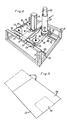
- the cutting device As shown in the drawings, the cutting device according to the invention, generally designated 1, has a substantially box-shaped frame 3 composed of square tubes 2. The inner width between the sides of the frame 3 approximately corresponds to the width of a ready-folded plastic carrier bag 4 (Fig. 3) supplied from an automatic welder (not shown) for a purpose described in greater detail hereinbelow.
- a cross beam 5 is mounted on the sides of the frame 3, there being provided approximately in the middle of the cross beam 5 a vertical double-acting pneumatic cylinder 6 whose inlet and outlet 7, 8 are connected to a source of compressed air (not shown) and whose piston rod 9 passes through a hole in the cross beam 5 and carries at its lower free end a hood-like holder generally designated 10.
- the holder has a covered top 11, two downwardly extending long sides 12 and a likewise downwardly extending short side 13 facing the automatic welder (not shown).
- the opposite short side 14 extends downwards only a short distance.
- the downwardly extending long and short sides 12, 13 cooperate with square tubes 15 mounted on the frame 3, in order to clamp the carrier bag 4 for a purpose which will be described in greater detail hereinbelow.
- the holder 10 On its underside and adjacent its four corners, the holder 10 carries four wheels of which one is a driving wheel 16 and the other three are idle wheels 17.
- the wheels 16 and 17 are toothed wheels, and a toothed belt 18 is passed over the wheels 16, 17 and carries on its outside a downwardly directed, readily interchangeable cutting knife 19.
- the driving wheel 16 is mounted on the free end of a screw spindle 20 in a ball bearing screw 21 whose nut (not shown) is connected to a double-acting pneumatic cylinder 22 for axial displacement of the nut and thereby rotation of the screw spindle 20 and the driving wheel 16.
- the driving wheel 16 can be mounted on the nut of the ball bearing screw 21, the screw spindle 20 being then connected to the pneumatic cylinder 22 and axially movable to rotate the nut and the driving wheel 16.
- the driving wheel 16 is caused, during each working cycle, to drive the toothed belt 18 in such a manner that the cutting knife 19 is moved from a starting position 23 (see Figs. 1 and 4) to an end position 24 (see Fig. 2) and from there back to the starting position.
- the cutting knife 19 will cut out the two handles 25 normally existing on plastic carrier bags, by cutting off the area 26 located within the dashed line in Fig. 3.
- the holder 10 In order that the carrier bag 4 should be secured in position during the cutting operation of the cutting knife 19 from the starting position 23 and up to the end position 24, the holder 10 is vertically movable by means of the pneumatic cylinder 6 from a resting position 27, shown in Fig. 2, to a lowered working position 28 in which the downwardly directed long and short sides 12, 13 of the holder 10 will press the plastic carrier bag 4 against the square tubes 15 serving as supports. After completion of the cutting operation, the holder 10 can be returned to the resting position 27 for releasing the carrier bag 4.
- the long and short sides 12, 13 and/or the square tubes 15 may be provided with interengaging friction-increasing rubber strips 29 or the like.
Landscapes
- Life Sciences & Earth Sciences (AREA)
- Forests & Forestry (AREA)
- Engineering & Computer Science (AREA)
- Mechanical Engineering (AREA)
- Making Paper Articles (AREA)
Applications Claiming Priority (2)
| Application Number | Priority Date | Filing Date | Title |
|---|---|---|---|
| SE8102762 | 1981-05-04 | ||
| SE8102762A SE425065B (sv) | 1981-05-04 | 1981-05-04 | Skeranordning, speciellt for tillskerning av handtag i berkassar och liknanande av plast |
Publications (2)
| Publication Number | Publication Date |
|---|---|
| EP0065504A2 true EP0065504A2 (fr) | 1982-11-24 |
| EP0065504A3 EP0065504A3 (fr) | 1984-06-13 |
Family
ID=20343721
Family Applications (1)
| Application Number | Title | Priority Date | Filing Date |
|---|---|---|---|
| EP82850088A Withdrawn EP0065504A3 (fr) | 1981-05-04 | 1982-04-28 | Machine à découper |
Country Status (2)
| Country | Link |
|---|---|
| EP (1) | EP0065504A3 (fr) |
| SE (1) | SE425065B (fr) |
Cited By (2)
| Publication number | Priority date | Publication date | Assignee | Title |
|---|---|---|---|---|
| EP0719620A3 (fr) * | 1994-12-27 | 1997-03-26 | Seiko Epson Corp | Méthode et dispositif pour couper un produit laminé en feuilles |
| CN109986644A (zh) * | 2019-03-08 | 2019-07-09 | 江苏华哲标签有限公司 | 一种标签打孔穿绳装置 |
Family Cites Families (7)
| Publication number | Priority date | Publication date | Assignee | Title |
|---|---|---|---|---|
| US2035946A (en) * | 1935-04-16 | 1936-03-31 | Edward M Cummings | Means for cutting film sheets such as phenol resin |
| US3294881A (en) * | 1963-11-29 | 1966-12-27 | Gen Motors Corp | Differential pressure forming and trim operations |
| US3673046A (en) * | 1969-06-23 | 1972-06-27 | Fmc Corp | Apparatus for splicing sheet materials |
| FR2112734A5 (en) * | 1970-11-06 | 1972-06-23 | Evrard Jacques | Thin plastic films - are cut to produce discs using orbiting cutter blade |
| US3772949A (en) * | 1972-01-17 | 1973-11-20 | Gerber Scientific Instr Co | Method and apparatus for cutting sheet material |
| DE2433548C2 (de) * | 1974-07-12 | 1983-04-28 | Franz 3553 Cölbe Rosenthal | Fräsvorrichtung für die Herstellung von Nuten im Rücken von Buchblöcken |
| US4111085A (en) * | 1977-05-10 | 1978-09-05 | Lockheed Corporation | Compound curvature cutting machine |
-
1981
- 1981-05-04 SE SE8102762A patent/SE425065B/sv not_active IP Right Cessation
-
1982
- 1982-04-28 EP EP82850088A patent/EP0065504A3/fr not_active Withdrawn
Cited By (2)
| Publication number | Priority date | Publication date | Assignee | Title |
|---|---|---|---|---|
| EP0719620A3 (fr) * | 1994-12-27 | 1997-03-26 | Seiko Epson Corp | Méthode et dispositif pour couper un produit laminé en feuilles |
| CN109986644A (zh) * | 2019-03-08 | 2019-07-09 | 江苏华哲标签有限公司 | 一种标签打孔穿绳装置 |
Also Published As
| Publication number | Publication date |
|---|---|
| EP0065504A3 (fr) | 1984-06-13 |
| SE425065B (sv) | 1982-08-30 |
Similar Documents
| Publication | Publication Date | Title |
|---|---|---|
| CN109043698B (zh) | 一种高速折叠口罩机 | |
| US5176060A (en) | Truss miter angle saws | |
| AU606122B2 (en) | Method and apparatus for cutting and deburring tubes | |
| CN105499332B (zh) | 一种折弯中心 | |
| US5014583A (en) | Push feed system for a saw | |
| US3758099A (en) | Clamp with workpiece locator | |
| US5074143A (en) | Cart for removing and installing dies in a cut-off press | |
| EP0186690B1 (fr) | Procede et dispositif pour placer des pieces de protection de rebords sur des objets ayant des rebords sensibles a la pression | |
| JPS60135197A (ja) | 樹脂成形物の直線トリミング装置 | |
| US4222323A (en) | Tire bundling machine | |
| EP0065504A2 (fr) | Machine à découper | |
| EP0240972B1 (fr) | Dispositif pour couper en travers des bandes en matière déformable | |
| US6719679B1 (en) | Perforation device | |
| KR100917578B1 (ko) | 절단기 | |
| CN209257171U (zh) | 一种推台锯 | |
| CN212527145U (zh) | 一种钣金件焊缝打磨设备 | |
| US3194096A (en) | Machine for cutting sheet materials | |
| CN206154379U (zh) | 一种用于二胡弦轴自动加工机的切断机构 | |
| CN214032546U (zh) | 一种皮革切割机的新型按压装置 | |
| CN217671425U (zh) | 一种在线式无纺布制袋机 | |
| CN211446130U (zh) | 一种便于喂扣的钉扣机 | |
| CA2063231A1 (fr) | Machine manuelle pour l'application de languettes sur une tole en feuille | |
| CN208995515U (zh) | 一种皮料切断分片夹持机构 | |
| JPH0653024U (ja) | アルミ材等の切断装置 | |
| US4167962A (en) | Slide assembly for a cutting machine |
Legal Events
| Date | Code | Title | Description |
|---|---|---|---|
| PUAI | Public reference made under article 153(3) epc to a published international application that has entered the european phase |
Free format text: ORIGINAL CODE: 0009012 |
|
| AK | Designated contracting states |
Designated state(s): AT BE CH DE FR GB IT NL |
|
| PUAL | Search report despatched |
Free format text: ORIGINAL CODE: 0009013 |
|
| AK | Designated contracting states |
Designated state(s): AT BE CH DE FR GB IT LI NL |
|
| STAA | Information on the status of an ep patent application or granted ep patent |
Free format text: STATUS: THE APPLICATION IS DEEMED TO BE WITHDRAWN |
|
| 18D | Application deemed to be withdrawn |
Effective date: 19850522 |