EP0065512A1 - Elément de treillis soudé tridimensionell résistant au cisaillement dans toutes les directions - Google Patents
Elément de treillis soudé tridimensionell résistant au cisaillement dans toutes les directions Download PDFInfo
- Publication number
- EP0065512A1 EP0065512A1 EP82890075A EP82890075A EP0065512A1 EP 0065512 A1 EP0065512 A1 EP 0065512A1 EP 82890075 A EP82890075 A EP 82890075A EP 82890075 A EP82890075 A EP 82890075A EP 0065512 A1 EP0065512 A1 EP 0065512A1
- Authority
- EP
- European Patent Office
- Prior art keywords
- wires
- grid
- mats
- longitudinal
- web
- Prior art date
- Legal status (The legal status is an assumption and is not a legal conclusion. Google has not performed a legal analysis and makes no representation as to the accuracy of the status listed.)
- Granted
Links
Images

Classifications
-
- E—FIXED CONSTRUCTIONS
- E04—BUILDING
- E04C—STRUCTURAL ELEMENTS; BUILDING MATERIALS
- E04C5/00—Reinforcing elements, e.g. for concrete; Auxiliary elements therefor
- E04C5/01—Reinforcing elements of metal, e.g. with non-structural coatings
- E04C5/06—Reinforcing elements of metal, e.g. with non-structural coatings of high bending resistance, i.e. of essentially three-dimensional [3D] extent, e.g. lattice girders
- E04C5/0636—Three-dimensional reinforcing mats composed of reinforcing elements laying in two or more parallel planes and connected by separate reinforcing parts
- E04C5/064—Three-dimensional reinforcing mats composed of reinforcing elements laying in two or more parallel planes and connected by separate reinforcing parts the reinforcing elements in each plane being formed by, or forming a, mat of longitunal and transverse bars
Definitions
- the invention relates to a three-dimensional welded lattice body, consisting of two parallel, flat lattice mats made of crossing and at the crossing points welded longitudinal and transverse wires and the lattice mats at a predetermined mutual distance, at each end with a wire one of the two lattice mats welded, cut straight web wires.
- Lattice bodies of this type are known, for example, from DE-A2-2 314 002 and serve mainly as reinforcement for composite components, the web wires of the lattice body carrying a heat-insulating core layer and the lattice mats protruding on both sides of this layer forming tragnets and surface reinforcements for outer shells made of concrete.
- all the web wires are arranged in an alternating opposite oblique position in planes running parallel to the longitudinal wires of the lattice mats and perpendicular to the mat surfaces.
- This known design of a spatial lattice body offers for the use as reinforcement for components of the type described above the advantage that the heat-insulating core layer is easily inserted in strip form in two opposite sides of the lattice mats and on two further opposite sides of web wires limited longitudinal channels of the lattice body can, on the other hand, limit the possible uses of the lattice body to those cases in which rigidity against shear in the direction of the transverse wires is not required. Given such a shear stress on the known spatial lattice body, the initially rectangular cross sections of the longitudinal channels mentioned can easily deform into parallelogram cross sections due to the lack of stiffening of the lattice body in the transverse direction.
- a spatial lattice body with two external lattice mats and intermediate webs in which the webs are formed by continuous, wavy wires in the direction of the longitudinal wires of the lattice mats, which are either perpendicular to the lattice mats Layers or in pairs in mutually inclined planes run so that four webs meet at one point and form the edges of a pyramid.
- the corrugated land wires are arranged in longitudinal planes perpendicular to the lattice mats, similar conditions result as for spatial lattice bodies of the type specified at the outset.
- a spatial reinforcement element which is formed from mutually parallel, ladder-like longitudinal elements which are connected vertically to one another by outer cross-wires forming grid meshes which are normal to their longitudinal extent, and by diagonal to these grid meshes running corrugated bridge wires are stiffened on all sides.
- Such reinforcement elements are so expensive in terms of their complicated structure that, as far as is known, they have not been used in practice.
- the invention is now concerned with the task of designing a lattice body of the type specified in the introduction in such a way that it is shear-resistant on all sides in such a way that it can be easily manufactured and in particular enables the web wire ends to be welded to the lattice wires using simple welding tongs.
- the spatial grid body is oblique to the normal planes on the cross wires extending web wires in the transverse direction and stiffened in the longitudinal direction by the web wires running obliquely to the normal planes on the longitudinal wires, so that the lattice body is shear-resistant in all directions.
- a particularly simple embodiment results if at least some of the web wires, but preferably all of them run obliquely to normal planes on the longitudinal wires and also obliquely to normal planes on the transverse wires of the two grid mats.
- each bridge wire has a stiffening effect in both the transverse and longitudinal directions.
- the lattice body according to the invention is to be used as a walk-in supporting structure, it is also advisable to cut the web wires to length with the outer sides of the two lattice mats so that they do not protrude beyond the lattice mats.
- the straight bridge wires used in the context of the invention already ensure a buckling stiffness which is desirable for rust-like structures, but this can be increased if necessary by forming the bridge wires with a larger diameter than the grid wires.
- the accessibility of such structures can be further favored by the fact that the grid wires of at least one of the two grid mats have a profiled surface.
- a spatial lattice body according to the invention can of course also be used as a component in a conventional manner Find use, then a layer of heat-insulating material is arranged in its central region, at a distance from the two lattice mats.
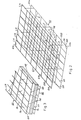
- two lattice mats G1 and G2 with aligned longitudinal and transverse wires L1-1-L1n and L21-L2n or Q11-Q1n and Q21-Q2n are at a predetermined distance from one another. They are held at this distance by cut straight web wires Sa, Sb or Sc, Sd, of which the former alternately in opposite directions obliquely between aligned longitudinal wires L11, L21 or L13, L23 etc., i.e. obliquely to normal planes on the longitudinal wires, and the latter alternately run in opposite directions obliquely between cross wires Q11, Q21 or Q13, Q23 etc.
- the lattice body is therefore stiffened both in the direction of the longitudinal wires of the lattice mats and in the direction of the transverse wires thereof and therefore shear-resistant on all sides.
- the ends of the bridge wires are at points P1 and P2 Longitudinal or transverse wires of the lattice mats G1 and G2 are welded, which are at intervals from crossing points K of the lattice wires, so that these points are easily accessible for simple welding guns.
- FIG. 2 shows another exemplary embodiment of the invention using the same designation as in FIG. 1, in which each web wire S runs from a point P2 lying within a longitudinal wire section of the lower lattice mat G2 to a point P1 on a longitudinal wire section of the upper lattice mat, which is offset approximately by a longitudinal wire pitch as well as approximately by a transverse wire pitch with respect to the point P1 on the grid mat G1.
- each web wire S has a stiffening effect both in the longitudinal direction and in the transverse direction of the lattice body.
- the welding points P1 and P2 of the ends of the web wires S with longitudinal wires of the grid mats G1 and G2 are again at a distance from the crossing points K of the grid wires.
- the web wires in spatial lattice bodies which are to be used as rust-like supporting structures, should end flush with a lattice mat level, that is, they should not protrude above this.
- the grid wires of a mat to be walked on can advantageously be profiled, for example ribbed, in order to increase the grip. By increasing the diameter of the bridge wires, their buckling stiffness and thus the load-bearing capacity of the structure can be increased.
- Such rusty structures can be used for work platforms, covers, formwork beams, however can also be used for prefabricated floor, wall and ceiling elements.
- a spatial lattice body according to the invention is suitable in a conventional manner for producing prefabricated components whose webs Sa, Sb, Sc and Sd have a core layer KS in the central region of the lattice body wear from heat-insulating material, whereby the freely protruding mesh mats G1 and G2 can be embedded in concrete and then form wall shells. It can be seen that the inclined webs running in different directions carry the core layer and hold it firmly in the central region of the lattice body.
Landscapes
- Engineering & Computer Science (AREA)
- Architecture (AREA)
- Civil Engineering (AREA)
- Structural Engineering (AREA)
- Wire Processing (AREA)
- Reinforcement Elements For Buildings (AREA)
Applications Claiming Priority (2)
| Application Number | Priority Date | Filing Date | Title |
|---|---|---|---|
| AT0215781A AT373330B (de) | 1981-05-14 | 1981-05-14 | Dreidimensionaler geschweisster gitterkoerper |
| AT2157/81 | 1981-05-14 |
Publications (2)
| Publication Number | Publication Date |
|---|---|
| EP0065512A1 true EP0065512A1 (fr) | 1982-11-24 |
| EP0065512B1 EP0065512B1 (fr) | 1985-01-16 |
Family
ID=3528976
Family Applications (1)
| Application Number | Title | Priority Date | Filing Date |
|---|---|---|---|
| EP82890075A Expired EP0065512B1 (fr) | 1981-05-14 | 1982-05-13 | Elément de treillis soudé tridimensionell résistant au cisaillement dans toutes les directions |
Country Status (4)
| Country | Link |
|---|---|
| EP (1) | EP0065512B1 (fr) |
| AT (1) | AT373330B (fr) |
| DE (1) | DE3261925D1 (fr) |
| ZA (1) | ZA823365B (fr) |
Cited By (2)
| Publication number | Priority date | Publication date | Assignee | Title |
|---|---|---|---|---|
| GB2196660A (en) * | 1986-10-29 | 1988-05-05 | Shimizu Construction Co Ltd | Wire mesh truss for wall panels |
| CN110616618A (zh) * | 2019-11-08 | 2019-12-27 | 南通大学 | 一种增强沥青基混凝土三维矩形格栅结构及其制备方法 |
Families Citing this family (1)
| Publication number | Priority date | Publication date | Assignee | Title |
|---|---|---|---|---|
| CN114197690B (zh) * | 2021-12-28 | 2023-09-26 | 河南盛都环保科技集团有限公司 | 一种带有固定件的钢筋混凝土被动式保温墙体 |
Citations (3)
| Publication number | Priority date | Publication date | Assignee | Title |
|---|---|---|---|---|
| US3305991A (en) * | 1964-12-14 | 1967-02-28 | Victor P Weismann | Reinforced modular foam panels |
| DE1659144A1 (de) * | 1967-10-19 | 1970-12-23 | Erwin Klein | Selbsttragendes Gitterwerk fuer die Armierung von flaechigen Isolierstoflbauelementen |
| DE2657667A1 (de) * | 1976-01-05 | 1977-07-14 | Cs & M Inc | Bauplatte mit einem aus metalldraht hergestellten gitterfachwerk, und verfahren sowie vorrichtung zu deren herstellung |
-
1981
- 1981-05-14 AT AT0215781A patent/AT373330B/de not_active IP Right Cessation
-
1982
- 1982-05-13 EP EP82890075A patent/EP0065512B1/fr not_active Expired
- 1982-05-13 ZA ZA823365A patent/ZA823365B/xx unknown
- 1982-05-13 DE DE8282890075T patent/DE3261925D1/de not_active Expired
Patent Citations (3)
| Publication number | Priority date | Publication date | Assignee | Title |
|---|---|---|---|---|
| US3305991A (en) * | 1964-12-14 | 1967-02-28 | Victor P Weismann | Reinforced modular foam panels |
| DE1659144A1 (de) * | 1967-10-19 | 1970-12-23 | Erwin Klein | Selbsttragendes Gitterwerk fuer die Armierung von flaechigen Isolierstoflbauelementen |
| DE2657667A1 (de) * | 1976-01-05 | 1977-07-14 | Cs & M Inc | Bauplatte mit einem aus metalldraht hergestellten gitterfachwerk, und verfahren sowie vorrichtung zu deren herstellung |
Cited By (3)
| Publication number | Priority date | Publication date | Assignee | Title |
|---|---|---|---|---|
| GB2196660A (en) * | 1986-10-29 | 1988-05-05 | Shimizu Construction Co Ltd | Wire mesh truss for wall panels |
| GB2196660B (en) * | 1986-10-29 | 1991-06-26 | Shimizu Construction Co Ltd | Wire mesh truss used as building wall element |
| CN110616618A (zh) * | 2019-11-08 | 2019-12-27 | 南通大学 | 一种增强沥青基混凝土三维矩形格栅结构及其制备方法 |
Also Published As
| Publication number | Publication date |
|---|---|
| ZA823365B (en) | 1983-03-30 |
| EP0065512B1 (fr) | 1985-01-16 |
| AT373330B (de) | 1984-01-10 |
| ATA215781A (de) | 1983-05-15 |
| DE3261925D1 (en) | 1985-02-28 |
Similar Documents
| Publication | Publication Date | Title |
|---|---|---|
| DE2821562B2 (de) | Bewehrungsgitter für Beton, insbesondere für die Sicherung unterirdischer Hohlräume | |
| DE1559490B1 (de) | Bewehrungselement fuer Balken und Stuetzen aus Stahlbeton | |
| EP0065512A1 (fr) | Elément de treillis soudé tridimensionell résistant au cisaillement dans toutes les directions | |
| DE2403717C2 (de) | Verbindungsanker für eine Mehrschichtenbauplatte | |
| DE3874539T2 (de) | Gittertraeger. | |
| EP0804658B1 (fr) | Treillis d'acier pour constructions en beton arme de grande surface | |
| DE2402000C3 (de) | Bewehrungsmatte für Stahlbetonbauteile | |
| AT377564B (de) | Bewehrungsmatte fuer stahlbeton | |
| DE2015952A1 (de) | Vorgefertigte Bewehrung für Bauteile aus Stahlbeton | |
| DE2454459A1 (de) | U-foermig profilierter metallkanal als traeger fuer kompakte geschossdecken aus leichtbloecken | |
| DE60007824T2 (de) | Gitterträger | |
| AT503489B1 (de) | Bauelement | |
| EP0097143B1 (fr) | Grillage d'armature pour béton armé | |
| AT406281B (de) | Stahlbetonbewehrung | |
| DE3625810A1 (de) | Gittertraeger | |
| AT371524B (de) | Bewehrungselement und verfahren zu dessen verlegung | |
| DE69708044T2 (de) | Konstruktionsteil | |
| DE1804703C3 (de) | Bewehrung für als verlorene Schalung dienende Stahlbetontafeln | |
| CH697250B1 (de) | Hohlwand-Bewehrungskorb. | |
| AT377563B (de) | Bewehrungmatte fuer stahlbeton | |
| AT360721B (de) | Platte fuer bauzwecke und plattenverband | |
| DE3120427A1 (de) | Bewehrung fuer die betondeckung von stahlbeton- oder spannbetonteilen | |
| DE1484328C (de) | Mehrschichtiges Bauelement | |
| DE2349923C3 (de) | Gitterträger für den Stahlbetonbau | |
| DE1484100C3 (de) | Geschweißte Bewehrungsmatte für Beton |
Legal Events
| Date | Code | Title | Description |
|---|---|---|---|
| PUAI | Public reference made under article 153(3) epc to a published international application that has entered the european phase |
Free format text: ORIGINAL CODE: 0009012 |
|
| AK | Designated contracting states |
Designated state(s): BE CH DE FR GB IT |
|
| 17P | Request for examination filed |
Effective date: 19821130 |
|
| ITF | It: translation for a ep patent filed | ||
| GRAA | (expected) grant |
Free format text: ORIGINAL CODE: 0009210 |
|
| AK | Designated contracting states |
Designated state(s): BE CH DE FR GB IT LI |
|
| REF | Corresponds to: |
Ref document number: 3261925 Country of ref document: DE Date of ref document: 19850228 |
|
| ET | Fr: translation filed | ||
| PLBE | No opposition filed within time limit |
Free format text: ORIGINAL CODE: 0009261 |
|
| STAA | Information on the status of an ep patent application or granted ep patent |
Free format text: STATUS: NO OPPOSITION FILED WITHIN TIME LIMIT |
|
| 26N | No opposition filed | ||
| PGFP | Annual fee paid to national office [announced via postgrant information from national office to epo] |
Ref country code: FR Payment date: 19900427 Year of fee payment: 9 |
|
| PGFP | Annual fee paid to national office [announced via postgrant information from national office to epo] |
Ref country code: GB Payment date: 19900501 Year of fee payment: 9 |
|
| PGFP | Annual fee paid to national office [announced via postgrant information from national office to epo] |
Ref country code: BE Payment date: 19900515 Year of fee payment: 9 |
|
| PGFP | Annual fee paid to national office [announced via postgrant information from national office to epo] |
Ref country code: DE Payment date: 19900731 Year of fee payment: 9 |
|
| PG25 | Lapsed in a contracting state [announced via postgrant information from national office to epo] |
Ref country code: GB Effective date: 19910513 |
|
| ITTA | It: last paid annual fee | ||
| PG25 | Lapsed in a contracting state [announced via postgrant information from national office to epo] |
Ref country code: BE Effective date: 19910531 |
|
| BERE | Be: lapsed |
Owner name: AVI ALPENLANDISCHE VEREDELUNGS-INDUSTRIE G.M.B.H. Effective date: 19910531 |
|
| GBPC | Gb: european patent ceased through non-payment of renewal fee | ||
| PG25 | Lapsed in a contracting state [announced via postgrant information from national office to epo] |
Ref country code: FR Effective date: 19920131 |
|
| PG25 | Lapsed in a contracting state [announced via postgrant information from national office to epo] |
Ref country code: DE Effective date: 19920303 |
|
| REG | Reference to a national code |
Ref country code: FR Ref legal event code: ST |
|
| PGFP | Annual fee paid to national office [announced via postgrant information from national office to epo] |
Ref country code: CH Payment date: 19950428 Year of fee payment: 14 |
|
| PG25 | Lapsed in a contracting state [announced via postgrant information from national office to epo] |
Ref country code: LI Effective date: 19960531 Ref country code: CH Effective date: 19960531 |
|
| REG | Reference to a national code |
Ref country code: CH Ref legal event code: PL |