EP0065557B1 - Installation pour la mesure du profil du rayonnement radioactif et moyen pour niveler l'intensite du rayonnement - Google Patents
Installation pour la mesure du profil du rayonnement radioactif et moyen pour niveler l'intensite du rayonnement Download PDFInfo
- Publication number
- EP0065557B1 EP0065557B1 EP19820900017 EP82900017A EP0065557B1 EP 0065557 B1 EP0065557 B1 EP 0065557B1 EP 19820900017 EP19820900017 EP 19820900017 EP 82900017 A EP82900017 A EP 82900017A EP 0065557 B1 EP0065557 B1 EP 0065557B1
- Authority
- EP
- European Patent Office
- Prior art keywords
- radiation
- detectors
- radiation intensity
- radioactive
- measuring
- Prior art date
- Legal status (The legal status is an assumption and is not a legal conclusion. Google has not performed a legal analysis and makes no representation as to the accuracy of the status listed.)
- Expired
Links
Images
Classifications
-
- G—PHYSICS
- G01—MEASURING; TESTING
- G01V—GEOPHYSICS; GRAVITATIONAL MEASUREMENTS; DETECTING MASSES OR OBJECTS; TAGS
- G01V5/00—Prospecting or detecting by the use of ionising radiation, e.g. of natural or induced radioactivity
- G01V5/02—Prospecting or detecting by the use of ionising radiation, e.g. of natural or induced radioactivity specially adapted for surface logging, e.g. from aircraft
Definitions
- the invention relates to a device for measuring radioactive radiation emitting from the ground to determine the radiation intensity gradient (s) present there.
- the invention also relates to a method for leveling the radiation intensity graded determined by this device.
- Known devices of this type are, for example, a so-called Geiger counter or a scintillation spectrometer, which are only used as one unit for determining the radiation intensity at a site.
- US Pat. No. 2,562,968 describes a system for measuring the intensity of the gamma rays emitted from the earth's surface at a specific measuring point for the purpose of prospecting mineral resources.
- two measuring devices arranged close to each other are used, one measuring device being shielded from the earth's radiation, while the other measuring device measures the cosmic radiation and the earth's radiation.
- This object is achieved according to the invention by at least two spaced apart from one another and above the ground to be measured, approximately at the same height and connected to a computing unit, which are combined with one another via the computing unit such that a display device controlled by the computing unit each Difference or the difference of the radiation intensities of the areas between the measuring points over which the detectors are currently located.
- a more or less precise radiation intensity profile of this terrain or building or of individual rooms can be determined by means of a measurement of the terrain or building that progresses gradually or at points along the coordinates of a coordinate system lying parallel to the plane to be measured. This can serve as the basis for the method which, as already mentioned at the beginning, is the subject of DE-OS 30 03 958.
- the local measured values can only be determined after a certain period of time has elapsed.
- the average times required for this are on the order of at least several minutes.
- the measurement of stimulation zones, stimulation strips or intersections has shown that fluctuations in the radioactive radiation intensity can be determined in an area of approximately 50 ⁇ 50 cm. Assuming a minimum measuring time of, for example, 5 minutes for a single measuring point, the measurement of an area of 50 x 50 cm with a measuring point spacing of 5 cm in each case would require a total of 100 measuring points and thus a total of 500 minutes, that is to say more than 8 hours.
- the method according to DE-OS 30 03 958 provides for a leveling of the local radiation intensity on properties, in houses and apartments by additionally attaching radioactive material via radiation sinks. This can be done on plots before building a house by bringing in and distributing suitable ones radioactive material such as sand, gravel or the like can be reached on the radiation sinks.
- the leveling can be achieved by placing precisely defined radioactive material for the exact removal of the radiation gradients under certain places, e.g. under beds, workplaces or other places of residence of people or under stables of all kinds for animals.
- the radioactive material used Since this backing is done by people, the radioactive material used must be packaged in such a way that direct contact or abrasion of the radioactive material is not possible. As explained above, this requirement is met by the subject matter of the invention.
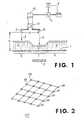
- the measuring device 12 has two detectors 2, 3 arranged at a variable distance A from one another, which are each arranged at approximately the same distance H above the latter and next to one another during the measurement of the ground 1.
- the two detectors 2, 3 of the measuring device 12 are connected to a single central receiving device 10, which can be switched alternately to one or the other detector 2, 3 in a suitable cycle. However, they can also be connected to separate receiving devices.
- the central receiving devices 10 can in turn be connected to a computer 4, which processes the radiation intensity values 6 ', 7' determined by the two detectors 2, 3, following a corresponding computing program, and in a suitable manner supplies them to a digital or analog display device 5 and thus making it accessible to human consciousness.
- a computer 4 which processes the radiation intensity values 6 ', 7' determined by the two detectors 2, 3, following a corresponding computing program, and in a suitable manner supplies them to a digital or analog display device 5 and thus making it accessible to human consciousness.
- These values can also be printed out using a printer (not shown here) or can be displayed in the form of a continuous curve using an automatic drawing device (also not shown here).
- the step-by-step determination of the difference or difference in radiation intensity 6 ', 7' between the measuring points 8, 9 in the direction of the coordinates of a coordinate system placed over the area 1 to be measured enables the desired radiation intensity profile to be determined precisely.
- the constant comparison of the radiation intensity values 6 ′, 7 ′ determined by the two detectors 2, 3 and the difference between these values is made very easy by the computer 4.
- the location of the stimulation zones for example water veins, faults, crossings or the like, can be determined correctly and precisely.
- the existing cosmic ultra-radiation superimposed on the two detectors 2, 3 is simultaneously switched off in terms of calculations. This is important because the cosmic ultra-radiation can fluctuate over time. If one were to make the difference by measuring with only one detector at different times at different locations, one would get different measurement data due to the temporal fluctuations of the superimposed cosmic ultra-radiation, which would lead to misleading conclusions about the actual radiation conditions over a certain area or in a certain area Can drive buildings.
- the differences in intensity of radioactive earth radiation set out in DE-OS 30 03 958 were determined using two similar measuring devices, for example using the Szintomats-6134 ID from Automess, Ladenburg. In this case, one measuring device had been set up on a fault or stimulus zone, while the other measuring device had been set up on a neutral-irritant location. The difference showed that the radiation intensity was lower over the stimulation zone than over the neutral area.
- a building or site area of 50 x 50 cm in size could be measured within 5 minutes.
- the simultaneous measurement with several measuring devices would reduce the temporal fluctuations of the radioactive radiation, which the radiation value to the individual Distortion of measuring points under the influence, in particular, of cosmic radiation, also taken into account.
- a measurement time of approximately 5 minutes proves to be sufficient for a rough assessment.
- a longer measuring time of 10 to 20 minutes is advisable for a more precise measurement. If you record the measurement data - so to speak in a snapshot after these 5 minutes - either manually or automatically on a measurement card representing the measurement surface, you get the profile of the radiation intensity of the measured surface, from which you can possibly draw very important conclusions about the Soil quality underneath the measuring surface can zichen (course of underground water veins, ground faults, rock formations, etc.).
- the measuring apparatus can be designed in such a way that the radioactivity is continuously measured by the detectors, even if their digital or analog display indicates apparent standstill.
- the counting of the radioactive impulses is recorded by means of appropriate memories, so that these measured values can also be evaluated later.
- the measuring accuracy can be increased accordingly by longer measuring times.
- the measuring grid of the measuring system can, of course, be changed so that it represents an optimum in the conflict of objectives between the economy on the one hand and the required measuring accuracy on the other.
- a frame of 200 x 200 cm with 400 measuring points will be more economical to use than a frame of 50 x 50 cm with 100 measuring points, even if this affects the measuring accuracy.
- using the larger frame saves time by more than 90% compared to the smaller frame if the same area is to be measured.
- the measurements are carried out sequentially and continuously over the area.
- the measured values obtained are then combined accordingly in order to obtain a complete profile of the radiation field of this area.
- This profile is of course also subject to the error that the measurement data determined over one measurement field of the total area can change quantitatively compared to the measurement data of the neighboring measurement field during the measurement of the total area due to the cosmic radiation already mentioned above, which leads to a falsification of the overall image of the Radiation profile of the total area can lead.
- a very large, close-meshed network of detectors would then have to be arranged over the entire surface, by means of which the entire field could be avoided in a snapshot.
- the radiation profile of the total area obtained in this way would of course offer the highest degree of accuracy and informative value.
- the apparatus here consists, for example, of a grid-like arrangement of about 25 detectors 102 to 126, which are attached to a rigid frame for measuring an area 101.
- a large number of detectors 102 to 126 which respond to radioactive radiation and are distributed uniformly or unevenly over this surface 101, are arranged above the area 101 to be measured, by means of which the instantaneous radiation intensities present at their locations can be measured simultaneously, the individual detectors 102 to 126 can be started simultaneously and switched off at the same time.
- the individual detectors 102 to 126 should be supplied by a common power source, designed to be transportable overall and controllable by a clock generator at selectable intervals.
- a method is proposed according to the invention, according to which the radiation intensity profile determined can be leveled or the radiation gradients eliminated.
- the areas with low radiation intensity 7 ' are leveled accordingly by means of a radioactive material in relation to the normal radiation intensity 6' of their surroundings, and the existing radiation gradients between the higher and the lower radiation level are thereby eliminated.
- care is taken to ensure that the radioactive material is packaged in a protective mass in such a way that it prevents direct physical contact with it during handling and prevents the distribution of radioactive particles in the air, in liquids or on the human, animal or plant body becomes.
- the radioactive material could be held between two or more plates, in particular made of veneer, plywood, chipboard or so-called insulating material, evenly distributed on their inner surfaces, in each case by means of adhesive or by welding, the radiation intensity of the enclosed radioactive material is printed on the outside of the agent enclosing it in order to avoid confusion.
- fibers, threads or wires with radioactive inclusions in particular in the form of a fabric or a fleece, are used. which are enclosed by sheathing, spinning, extrusion coating or dipping in such a way that direct contact with the radioactive material is prevented.
Landscapes
- Physics & Mathematics (AREA)
- Engineering & Computer Science (AREA)
- Aviation & Aerospace Engineering (AREA)
- High Energy & Nuclear Physics (AREA)
- Life Sciences & Earth Sciences (AREA)
- General Life Sciences & Earth Sciences (AREA)
- General Physics & Mathematics (AREA)
- Geophysics (AREA)
- Measurement Of Radiation (AREA)
Claims (15)
Priority Applications (1)
| Application Number | Priority Date | Filing Date | Title |
|---|---|---|---|
| AT82900017T ATE18700T1 (de) | 1980-12-03 | 1981-12-03 | Vorrichtung zur messung des radioaktiven strahlungsprofils auf der erdoberflaeche und mittel zur homogenisierung der ermittelten strahlungsintensitaet. |
Applications Claiming Priority (4)
| Application Number | Priority Date | Filing Date | Title |
|---|---|---|---|
| DE3045578 | 1980-12-03 | ||
| DE19803045578 DE3045578A1 (de) | 1980-12-03 | 1980-12-03 | System zur messung radioaktiver strahlung |
| DE19813147895 DE3147895A1 (de) | 1981-12-03 | 1981-12-03 | Gegenstand zur nivellierung von radioaktiver strahlungs-intensitaet |
| DE19813147894 DE3147894A1 (de) | 1981-12-03 | 1981-12-03 | System zur messung radioaktiver strahlung |
Publications (2)
| Publication Number | Publication Date |
|---|---|
| EP0065557A1 EP0065557A1 (fr) | 1982-12-01 |
| EP0065557B1 true EP0065557B1 (fr) | 1986-03-19 |
Family
ID=27188982
Family Applications (1)
| Application Number | Title | Priority Date | Filing Date |
|---|---|---|---|
| EP19820900017 Expired EP0065557B1 (fr) | 1980-12-03 | 1981-12-03 | Installation pour la mesure du profil du rayonnement radioactif et moyen pour niveler l'intensite du rayonnement |
Country Status (3)
| Country | Link |
|---|---|
| EP (1) | EP0065557B1 (fr) |
| AU (1) | AU7930682A (fr) |
| WO (1) | WO1982002097A1 (fr) |
Families Citing this family (1)
| Publication number | Priority date | Publication date | Assignee | Title |
|---|---|---|---|---|
| WO2005022197A2 (fr) * | 2003-07-18 | 2005-03-10 | Radioact Corporation | Procedes et appareils de detection et de localisation de matieres dangereuses |
Family Cites Families (6)
| Publication number | Priority date | Publication date | Assignee | Title |
|---|---|---|---|---|
| US2562968A (en) * | 1948-03-09 | 1951-08-07 | Texas Co | Prospecting |
| US2562962A (en) * | 1948-03-09 | 1951-08-07 | Texas Co | Prospecting |
| GB722015A (en) * | 1951-08-14 | 1955-01-19 | Texaco Development Corp | Improvements in or relating to prospecting |
| FR1427794A (fr) * | 1964-12-10 | 1966-02-11 | Commissariat Energie Atomique | Procédé de contrôle de la contamination radioactive de surfaces et dispositif en faisant application |
| US3812363A (en) * | 1971-11-18 | 1974-05-21 | A Abakarovich | Probe for measuring characteristics of subsurface and ground water flow |
| DE3003958A1 (de) * | 1980-02-04 | 1981-08-13 | Gerald Dipl.-Ing. 8501 Rückersdorf Klein | Verfahren zur homogenisierung bzw. nivellierung der in einem bestimmten gelaende oder gebaeude vom erdboden abstrahlenden radioaktiven strahlung |
-
1981
- 1981-12-03 EP EP19820900017 patent/EP0065557B1/fr not_active Expired
- 1981-12-03 AU AU79306/82A patent/AU7930682A/en not_active Abandoned
- 1981-12-03 WO PCT/DE1981/000213 patent/WO1982002097A1/fr not_active Ceased
Also Published As
| Publication number | Publication date |
|---|---|
| AU7930682A (en) | 1982-07-01 |
| WO1982002097A1 (fr) | 1982-06-24 |
| EP0065557A1 (fr) | 1982-12-01 |
Similar Documents
| Publication | Publication Date | Title |
|---|---|---|
| EP0212275B1 (fr) | Procédé pour déterminer les limites des couches de gaz naturel souterrain | |
| DE2743009C2 (fr) | ||
| DE2462509C3 (de) | Radiographisches Gerät zum Untersuchen der Absorption von Röntgen- oder Gamma-Strahlung in einer Querschnittscheibe eines Körpers | |
| DE69728894T2 (de) | Vorrichtung und verfahren zur signalverarbeitung der photodetektoranordnung einer gammakamera | |
| DE69005586T2 (de) | Vorrichtung zur Messung der Strahlungsverseuchung von grossen Objekten. | |
| DE3136343A1 (de) | Verfahren und vorrichtung zum analysieren von erz unter einsatz von gammastrahlung | |
| EP0065557B1 (fr) | Installation pour la mesure du profil du rayonnement radioactif et moyen pour niveler l'intensite du rayonnement | |
| WO2003007018A2 (fr) | Procede et dispositif pour determiner la dose individuelle dans des champs mixtes de neutrons et de photons | |
| DE2946003C2 (de) | Verfahren zum Ermitteln von Strahlungsmeßwerten von mehreren an bestimmten Bereitstellungsorten in einem Strahlungsmeßgerät angeordneten radioaktiven Proben | |
| DE2011104B2 (de) | Geraet zum aufnehmen und aufzeichnen der raeumlichen verteilung radioaktiver strahlungsquellen in einem untersuchungsobjekt mit einer szintillationskamera und mit mitteln zur selektiven scharfeinstellung auf eine waehlbare schnittebene | |
| DE3736873A1 (de) | Anordnung zur kurzfristigen vorhersage von erdbeben | |
| DE102007032270A1 (de) | Vorrichtung zum Prüfen von Produkten und Prüfverfahren | |
| DE3147894A1 (de) | System zur messung radioaktiver strahlung | |
| DE3618368A1 (de) | Verfahren zur momentanerfassung, trendanalyse und langzeitverfolgung von strahlenbelastungen im privaten lebensraum sowie vorrichtung zur durchfuehrung des verfahrens | |
| EP0434705B1 (fr) | Dispositif de mesure de l'activite et du volume de liquides radioactifs | |
| DE19614785A1 (de) | Meßsystem zur Erfassung von Niederschlagsmengen | |
| DE102020119065A1 (de) | Verfahren zum Entscheidungsmessen eines Messguts unter Verwendung einer Freimessanlage, Computerprogrammprodukt sowie Freimessanlage | |
| DE3304742A1 (de) | Verfahren zur ermittlung geopathogener zonen | |
| DE3045578A1 (de) | System zur messung radioaktiver strahlung | |
| EP2439557B1 (fr) | Procédé de détermination de l'activité ß de l'isotope de carbone C14 | |
| DE1589843C3 (de) | Verfahren zur Ortung eines radioaktiv markierten Organes des menschlichen oder tierischen Körpers | |
| DE1179307B (de) | Einrichtung zum Erfassen der flaechenhaften Verteilung einer radioaktiven Strahlung | |
| DE3837622A1 (de) | Vorrichtung zur abschirmung und absorption sowie zur erzeugung von strahlung (erdstrahlung) | |
| DE2044662A1 (de) | Vorrichtung zur selbsttätigen Anzeige der Bewegung von Lebewesen | |
| EP3757623A1 (fr) | Procédé de localisation des zones de radioactivité élevée dans un produit à mesurer |
Legal Events
| Date | Code | Title | Description |
|---|---|---|---|
| PUAI | Public reference made under article 153(3) epc to a published international application that has entered the european phase |
Free format text: ORIGINAL CODE: 0009012 |
|
| AK | Designated contracting states |
Designated state(s): AT CH DE FR GB LI LU NL SE |
|
| 17P | Request for examination filed |
Effective date: 19821124 |
|
| GRAA | (expected) grant |
Free format text: ORIGINAL CODE: 0009210 |
|
| AK | Designated contracting states |
Kind code of ref document: B1 Designated state(s): AT CH DE FR GB LI LU NL SE |
|
| PG25 | Lapsed in a contracting state [announced via postgrant information from national office to epo] |
Ref country code: NL Effective date: 19860319 Ref country code: FR Free format text: THE PATENT HAS BEEN ANNULLED BY A DECISION OF A NATIONAL AUTHORITY Effective date: 19860319 |
|
| REF | Corresponds to: |
Ref document number: 18700 Country of ref document: AT Date of ref document: 19860415 Kind code of ref document: T |
|
| PG25 | Lapsed in a contracting state [announced via postgrant information from national office to epo] |
Ref country code: SE Effective date: 19860331 |
|
| REF | Corresponds to: |
Ref document number: 3174160 Country of ref document: DE Date of ref document: 19860424 |
|
| EN | Fr: translation not filed | ||
| NLV1 | Nl: lapsed or annulled due to failure to fulfill the requirements of art. 29p and 29m of the patents act | ||
| PG25 | Lapsed in a contracting state [announced via postgrant information from national office to epo] |
Ref country code: AT Effective date: 19861203 |
|
| PG25 | Lapsed in a contracting state [announced via postgrant information from national office to epo] |
Ref country code: LU Free format text: LAPSE BECAUSE OF NON-PAYMENT OF DUE FEES Effective date: 19861231 Ref country code: LI Effective date: 19861231 Ref country code: CH Effective date: 19861231 |
|
| PLBE | No opposition filed within time limit |
Free format text: ORIGINAL CODE: 0009261 |
|
| STAA | Information on the status of an ep patent application or granted ep patent |
Free format text: STATUS: NO OPPOSITION FILED WITHIN TIME LIMIT |
|
| 26N | No opposition filed | ||
| GBPC | Gb: european patent ceased through non-payment of renewal fee | ||
| REG | Reference to a national code |
Ref country code: CH Ref legal event code: PL |
|
| PG25 | Lapsed in a contracting state [announced via postgrant information from national office to epo] |
Ref country code: GB Free format text: LAPSE BECAUSE OF NON-PAYMENT OF DUE FEES Effective date: 19881121 |
|
| PGFP | Annual fee paid to national office [announced via postgrant information from national office to epo] |
Ref country code: DE Payment date: 19900423 Year of fee payment: 9 |
|
| PG25 | Lapsed in a contracting state [announced via postgrant information from national office to epo] |
Ref country code: DE Effective date: 19910903 |