EP0065578A1 - Schutzbrille bzw. Schutzhelm mit integrierter Geschwindigkeits-, Zeit- und Höhenmessung - Google Patents
Schutzbrille bzw. Schutzhelm mit integrierter Geschwindigkeits-, Zeit- und Höhenmessung Download PDFInfo
- Publication number
- EP0065578A1 EP0065578A1 EP81103906A EP81103906A EP0065578A1 EP 0065578 A1 EP0065578 A1 EP 0065578A1 EP 81103906 A EP81103906 A EP 81103906A EP 81103906 A EP81103906 A EP 81103906A EP 0065578 A1 EP0065578 A1 EP 0065578A1
- Authority
- EP
- European Patent Office
- Prior art keywords
- pressure sensor
- time
- remote control
- helmet
- pulse
- Prior art date
- Legal status (The legal status is an assumption and is not a legal conclusion. Google has not performed a legal analysis and makes no representation as to the accuracy of the status listed.)
- Granted
Links
- 230000001681 protective effect Effects 0.000 title abstract description 7
- 238000005259 measurement Methods 0.000 claims abstract description 6
- 239000005336 safety glass Substances 0.000 claims description 5
- 238000011156 evaluation Methods 0.000 claims description 2
- 210000001061 forehead Anatomy 0.000 abstract description 3
- 239000011521 glass Substances 0.000 abstract description 2
- 230000006835 compression Effects 0.000 abstract 1
- 238000007906 compression Methods 0.000 abstract 1
- 210000004936 left thumb Anatomy 0.000 description 2
- 210000004935 right thumb Anatomy 0.000 description 2
- 241000380131 Ammophila arenaria Species 0.000 description 1
- 230000000694 effects Effects 0.000 description 1
- 210000003128 head Anatomy 0.000 description 1
Images

Classifications
-
- A—HUMAN NECESSITIES
- A42—HEADWEAR
- A42B—HATS; HEAD COVERINGS
- A42B3/00—Helmets; Helmet covers ; Other protective head coverings
- A42B3/04—Parts, details or accessories of helmets
- A42B3/18—Face protection devices
- A42B3/185—Securing goggles or spectacles on helmet shells
-
- A—HUMAN NECESSITIES
- A42—HEADWEAR
- A42B—HATS; HEAD COVERINGS
- A42B3/00—Helmets; Helmet covers ; Other protective head coverings
- A42B3/04—Parts, details or accessories of helmets
- A42B3/0406—Accessories for helmets
- A42B3/0433—Detecting, signalling or lighting devices
-
- A—HUMAN NECESSITIES
- A61—MEDICAL OR VETERINARY SCIENCE; HYGIENE
- A61F—FILTERS IMPLANTABLE INTO BLOOD VESSELS; PROSTHESES; DEVICES PROVIDING PATENCY TO, OR PREVENTING COLLAPSING OF, TUBULAR STRUCTURES OF THE BODY, e.g. STENTS; ORTHOPAEDIC, NURSING OR CONTRACEPTIVE DEVICES; FOMENTATION; TREATMENT OR PROTECTION OF EYES OR EARS; BANDAGES, DRESSINGS OR ABSORBENT PADS; FIRST-AID KITS
- A61F9/00—Methods or devices for treatment of the eyes; Devices for putting in contact-lenses; Devices to correct squinting; Apparatus to guide the blind; Protective devices for the eyes, carried on the body or in the hand
- A61F9/02—Goggles
- A61F9/029—Additional functions or features, e.g. protection for other parts of the face such as ears, nose or mouth; Screen wipers or cleaning devices
-
- G—PHYSICS
- G01—MEASURING; TESTING
- G01D—MEASURING NOT SPECIALLY ADAPTED FOR A SPECIFIC VARIABLE; ARRANGEMENTS FOR MEASURING TWO OR MORE VARIABLES NOT COVERED IN A SINGLE OTHER SUBCLASS; TARIFF METERING APPARATUS; MEASURING OR TESTING NOT OTHERWISE PROVIDED FOR
- G01D11/00—Component parts of measuring arrangements not specially adapted for a specific variable
- G01D11/30—Supports specially adapted for an instrument; Supports specially adapted for a set of instruments
-
- G—PHYSICS
- G02—OPTICS
- G02B—OPTICAL ELEMENTS, SYSTEMS OR APPARATUS
- G02B27/00—Optical systems or apparatus not provided for by any of the groups G02B1/00 - G02B26/00, G02B30/00
- G02B27/01—Head-up displays
- G02B27/017—Head mounted
-
- G—PHYSICS
- G02—OPTICS
- G02B—OPTICAL ELEMENTS, SYSTEMS OR APPARATUS
- G02B27/00—Optical systems or apparatus not provided for by any of the groups G02B1/00 - G02B26/00, G02B30/00
- G02B27/01—Head-up displays
- G02B27/0101—Head-up displays characterised by optical features
- G02B2027/014—Head-up displays characterised by optical features comprising information/image processing systems
Definitions
- the invention relates to safety glasses or a safety helmet with integrated speed, time and height measurement, which can be seen continuously by a person wearing the safety glasses or safety helmet via a display. All sensors and display elements, including the evaluation electronics, are housed on the safety glasses or hard hat.
- the invention enables, inter alia, in sports (e.g. skiing, hang-gliding, etc.) a person to easily monitor the hourly speed in relation to the air, the altitude depending on the barometric air pressure and the time relative to a starting time.
- sports e.g. skiing, hang-gliding, etc.
- the LCD display can be used to display the speed (relative to air), the time of the electronic stopwatch or the barometric altitude (derived from the absolute pressure sensor) via an electronic advance. Electronic advancement takes place remotely via two push buttons.
- the push buttons are located at the upper end of the two ski poles and can be operated by the left and right thumb. Pressing a push button causes a transmitter to emit a pulse which is received by a receiver in the protective goggles or the protective helmet.
- the receiver can use the transmitted frequencies (or modulations) to differentiate whether key 1, key 2 or both keys have been pressed.
- the current speed to air, the altitude derived from the barometric pressure or the time related to a start time can be monitored by the eye without affecting the current activity (e.g. skiing).
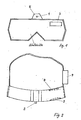
- Figure 1 shows the top view of a pair of goggles common in skiing.
- the pitot tube (1) with pressure sensor (2) for absorbing the air pressure is located at the middle of the forehead at the upper edge.
- the electrical signal generated by the pressure sensor (2) and proportional to the dynamic pressure is passed to a container (9) in which the signal processing electronics, batteries, an absolute pressure sensor, an electronic stop watch and a remote control receiver are accommodated.
- the electronics convert the signal supplied by the pressure sensor (2) into a corresponding speed value and the signal supplied by the absolute pressure sensor into a barometric altitude value.
- These two values and the value supplied by the electronic stopwatch can be displayed on the LCD display (4).
- the LCD display (4) is located directly above one eye (see Fig. 3) and has thermal contact with the forehead in order to work safely even at low ambient temperatures.
- the values are shown in mirror writing on the LCD display (4) and are mirrored in the field of vision by the eye via a converging lens with a mirrored back or concave mirror (3).
- the display changes from time measurement to speed or altitude measurement via the pulse buttons (5 and 6) (see Fig. 4), which are located at the upper end of the two ski poles and can be operated by the right and left thumb.
- buttons built-in transmitter in the ski stick handles (7 and 8) By pressing the buttons built-in transmitter in the ski stick handles (7 and 8) causes pulses to be received which are received by the remote control receiver in the container (9).
Landscapes
- Health & Medical Sciences (AREA)
- Physics & Mathematics (AREA)
- General Physics & Mathematics (AREA)
- Biomedical Technology (AREA)
- Public Health (AREA)
- Heart & Thoracic Surgery (AREA)
- Vascular Medicine (AREA)
- Life Sciences & Earth Sciences (AREA)
- Animal Behavior & Ethology (AREA)
- General Health & Medical Sciences (AREA)
- Engineering & Computer Science (AREA)
- Veterinary Medicine (AREA)
- Ophthalmology & Optometry (AREA)
- Otolaryngology (AREA)
- Optics & Photonics (AREA)
- Electric Clocks (AREA)
- Telescopes (AREA)
- Eyeglasses (AREA)
- Helmets And Other Head Coverings (AREA)
Abstract
Description
- Die Erfindung bezieht sich auf eine Schutzbrille bzw. einen Schutzhelm mit integrierter Geschwindigkeits-, Zeit - und Höhenmessung, die von einer die Schutzbrille bzw. den Schutzhelm tragenden Person ständig über eine Anzeige gesehen werden kann. Hierbei sind an der Schutzbrille bzw. dem Schutzhelm alle Sensoren und Anzeigeelemente incl. der Auswerteelektronik untergebracht.
- Die Erfindung ermöglicht unter anderem bei Sport ( z. B. Skifahren, Drachenfliegen usw. ) einer Person problemlos ein stündiges Überwachen der Geschwindigkeit gegenüber der Luft, der Höhe abhängig vom barometrischen Luftdruck und der Zeit relativ zu einem Startzeitpunkt.
- Die Erfindung löst die Aufgabe gemäß folgendem Aufbau:
- An der Schutzbrille bzw. dem Schutzhelm befindet sich in der Mitte von der Stirnseite ein Staurohr in dem bei einer relativen Geschwindigkeit zur Luft ein Staudruck entsteht, der zu einem " piezzoresistiven " Druckaufnehmer geführt wird. Der Druckaufnehmer erzeugt ein dem Staudruck proportionales Signal, das von einer an der Brille bzw. dem Helm mitgeführten Elektronik in ein der momentanen Geschwindigkeit relativ zur Luft entsprechendes Signal umgewandelt, digitalisiert und zu einer LCD-Anzeige geführt wird. Die LCD-Anzeige befindet sich über einem Auge und hat thermischen Kontakt zum Kopf. Die Darstellung auf der LCD-Anzeige erfolgt in Spiegelschrift. Die Anzeige wird über einen an der Durchsichtscheibe angebrachten Hohlspiegel oder eine verspiegelte Sammellinse für das Auge akkommodierbar in das Blickfeld eingespiegelt. Neben dem Staurohr mit Druckaufnehmerist in der Schutzbrille bzw. dem Schutzhelm eine elektronische Stopuhr und ein " Piezzo - Absolutdruckaufnehmer " untergebracht.
- Über eine elektronische Fortschaltung kann wahlweise mit der LCD-Anzeige die Geschwindigkeit( relativ zur Luft ) die Zeit der elektronischen Stopuhr oder die barometrische Höhe ( abgeleitet vom Absolutdruckaufnehmer ) zur Anzeige gebracht werden. Die elektronische Fortschaltung erfolgt ferngesteuert über zwei Drucktasten. Die Drucktasten befinden sich bei Einsatz der Erfindung beim Skisport am oberen Ende der beiden Skistöcke und können vom linken und rechten Daumen betätigt werden. Das Betätigen einer Drucktaste veranlaßt einen Sender einen Puls abzugeben, der von einem Empfänger in der Schutzbrille bzw. dem Schutzhelm empfangen wird. Der Empfänger kann über die gesendeten Frequenzen ( oder Modulationen ) unterscheiden ob Taste 1, 'Taste 2 oder beide Tasten betätigt wurden. Die durch die Erfindung erreichten Vorteile sind darin zu sehen, daß z.B. während der Ausübung einer Sportart, wie Skifahren oder Drachenfliegen, problemlos die momentane Geschwindigkeitzur Luft, die Höhe abgeleitet vom barometrischen Druck oder die Zeit bezogen auf einen Startzeitpunkt durch das Auge überwacht werden kann, ohne daß die momentane Tätigkeit ( z.B. Skisport ) beeinträchtigt wird.
- Im folgenden wird die Erfindung mit einem Ausführungsweg beim Einsatz im Skisport mit darstellenden Zeichnungen näher erläutert.
- Figur 1 zeigt die Draufsichtauf eine beim Skifahren übliche Schutzbrille. An der Stirnmitte am oberen Rand befindet sich das Staurohr ( 1 ) mit Druckaufnehmer ( 2 ) zur Aufnahme des Luftstaudrucks.
- Das vom Druckaufnehmer ( 2 ) erzeugte und dem Staudruck proportionale elektrische Signal wird zu einem Behälter (9) geleitet, in dem die signalverarbeitende Elektronik, Batterien, ein Absolutdruckaufnehmer, eine elektronische Stopuhr und einFernsteuerempfänger untergebracht sind. Die Elektronik wandelt das vom Druckaufnehmer ( 2 ) gelieferte Signal in einen entsprechenden Geschwindigkeitswert und das vom Absolutdruckaufnehmer gelieferte Signal in einen barometrischen Höhenwert um. Diese beiden Werte und der von der elektronischen Stopuhr gelieferte Wert können auf der LCD-Anzeige ( 4 ) zur Anzeige gebracht werden. Die LCD-Anzeige ( 4 ) befindet sich direkt über einem Auge ( s. Fig. 3 ) und hat thermischen Kontakt zur Stirn um auch bei niedrigen Umgebungstemperaturen sicher zu arbeiten. Die Werte werden an der LCD-Anzeige ( 4 ) in Spiegelschrift dargestellt und über eine Sammellinse mit verspiegelter Rückseite oder Hohlspiegel ( 3 ) für das Auge akkommodierbar in das Blickfeld eingespiegelt. Die Fortschaltung der Anzeige von Zeitmessung auf Geschwindigkeits - oder Höhenmessung erfolgt über die Pulstasten ( 5 u. 6 ) ( s. Fig. 4 ), die sich am oberen Ende der beiden Skistöcke befinden und vom rechten und linken Daumen betätigt werden können.
- Durch das Betätigen der Tasten werden in den Skistockgriffen ( 7 u. 8 ) eingebaute Sender veranlaßt Pulse abzugeben, die vom Fernsteuerempfänger im Behälter ( 9 ) empfangen werden.
- Im einzelnen bedeutet das Betätigen der Pulstasten folgendes :
- Pulstaste von Skistock 1 : Start/Stop für Zeitmessung
- Pulstaste von Skistock 2 : Fortschaltung der Funktion
- Pulstaste von Skistock 1 u. 2 : Zurücksetzen in Ausgangslage
Claims (3)
Priority Applications (3)
| Application Number | Priority Date | Filing Date | Title |
|---|---|---|---|
| AT81103906T ATE16450T1 (de) | 1981-05-21 | 1981-05-21 | Schutzbrille bzw. schutzhelm mit integrierter geschwindigkeits-, zeit- und hoehenmessung. |
| DE8181103906T DE3172881D1 (en) | 1981-05-21 | 1981-05-21 | Protective goggles or helmet with integral speed, time and altitude measuring means |
| EP81103906A EP0065578B1 (de) | 1981-05-21 | 1981-05-21 | Schutzbrille bzw. Schutzhelm mit integrierter Geschwindigkeits-, Zeit- und Höhenmessung |
Applications Claiming Priority (1)
| Application Number | Priority Date | Filing Date | Title |
|---|---|---|---|
| EP81103906A EP0065578B1 (de) | 1981-05-21 | 1981-05-21 | Schutzbrille bzw. Schutzhelm mit integrierter Geschwindigkeits-, Zeit- und Höhenmessung |
Publications (2)
| Publication Number | Publication Date |
|---|---|
| EP0065578A1 true EP0065578A1 (de) | 1982-12-01 |
| EP0065578B1 EP0065578B1 (de) | 1985-11-13 |
Family
ID=8187726
Family Applications (1)
| Application Number | Title | Priority Date | Filing Date |
|---|---|---|---|
| EP81103906A Expired EP0065578B1 (de) | 1981-05-21 | 1981-05-21 | Schutzbrille bzw. Schutzhelm mit integrierter Geschwindigkeits-, Zeit- und Höhenmessung |
Country Status (3)
| Country | Link |
|---|---|
| EP (1) | EP0065578B1 (de) |
| AT (1) | ATE16450T1 (de) |
| DE (1) | DE3172881D1 (de) |
Cited By (6)
| Publication number | Priority date | Publication date | Assignee | Title |
|---|---|---|---|---|
| EP0574096A1 (de) * | 1986-09-25 | 1993-12-15 | Insight, Inc. | Auf dem Kopf getragenes Anzeigesystem |
| GB2283333A (en) * | 1993-10-29 | 1995-05-03 | John Charles Irvine | Divers mask having a display |
| EP0665686A3 (de) * | 1993-12-03 | 1998-03-18 | Texas Instruments Incorporated | Visuelles Informationssystem |
| FR2834865A1 (fr) * | 2002-01-22 | 2003-07-25 | Martinod Thierry Marin | Dispositif de detection d'un risque de verglas pour motard, visiere et casque le comportant |
| US7150047B2 (en) * | 2003-07-02 | 2006-12-19 | Lightswitch Safety Systems, Inc. | Indicator layout on an auto-darkening lens for use in welding |
| WO2010016084A1 (en) * | 2008-08-04 | 2010-02-11 | Andrea Davighi | Protective helmet with a speed measuring system and processor for data storage. |
Citations (2)
| Publication number | Priority date | Publication date | Assignee | Title |
|---|---|---|---|---|
| DE2619947A1 (de) * | 1976-05-06 | 1977-11-10 | Weltin Optac | Einrichtung zur uebermittlung von informationen |
| US4231117A (en) * | 1979-01-15 | 1980-11-04 | Gentex Corporation | Helmet assembly for accurately positioning visual display system |
-
1981
- 1981-05-21 DE DE8181103906T patent/DE3172881D1/de not_active Expired
- 1981-05-21 AT AT81103906T patent/ATE16450T1/de not_active IP Right Cessation
- 1981-05-21 EP EP81103906A patent/EP0065578B1/de not_active Expired
Patent Citations (2)
| Publication number | Priority date | Publication date | Assignee | Title |
|---|---|---|---|---|
| DE2619947A1 (de) * | 1976-05-06 | 1977-11-10 | Weltin Optac | Einrichtung zur uebermittlung von informationen |
| US4231117A (en) * | 1979-01-15 | 1980-11-04 | Gentex Corporation | Helmet assembly for accurately positioning visual display system |
Non-Patent Citations (1)
| Title |
|---|
| Aviation Week and Space Technology, Band 106, Nr. 20, Mai 1977, New York (US) B. MILLER: "Navy Studies Helmetmounted Display", seiten 52, 53 * seite 52, spalte 1, zeile 1 bis seite 53, spalte 1, zeile 16 * * |
Cited By (6)
| Publication number | Priority date | Publication date | Assignee | Title |
|---|---|---|---|---|
| EP0574096A1 (de) * | 1986-09-25 | 1993-12-15 | Insight, Inc. | Auf dem Kopf getragenes Anzeigesystem |
| GB2283333A (en) * | 1993-10-29 | 1995-05-03 | John Charles Irvine | Divers mask having a display |
| EP0665686A3 (de) * | 1993-12-03 | 1998-03-18 | Texas Instruments Incorporated | Visuelles Informationssystem |
| FR2834865A1 (fr) * | 2002-01-22 | 2003-07-25 | Martinod Thierry Marin | Dispositif de detection d'un risque de verglas pour motard, visiere et casque le comportant |
| US7150047B2 (en) * | 2003-07-02 | 2006-12-19 | Lightswitch Safety Systems, Inc. | Indicator layout on an auto-darkening lens for use in welding |
| WO2010016084A1 (en) * | 2008-08-04 | 2010-02-11 | Andrea Davighi | Protective helmet with a speed measuring system and processor for data storage. |
Also Published As
| Publication number | Publication date |
|---|---|
| DE3172881D1 (en) | 1985-12-19 |
| ATE16450T1 (de) | 1985-11-15 |
| EP0065578B1 (de) | 1985-11-13 |
Similar Documents
| Publication | Publication Date | Title |
|---|---|---|
| EP1374758B1 (de) | Vorrichtung zur Erfassung von Messwerten an einem Auge | |
| EP0532572A1 (de) | Pulsabnehmer | |
| US5685722A (en) | Electronic timing swimmer's goggles | |
| US4991850A (en) | Golf swing evaluation system | |
| US6431705B1 (en) | Eyewear heart rate monitor | |
| US4949072A (en) | Dive parameter indicating assembly | |
| US4129124A (en) | Pulse-rate indicator | |
| US4406290A (en) | Wrist-type pulse monitor | |
| US4694694A (en) | Solid state accumulating altimeter | |
| US4835716A (en) | Compact measuring apparatus capable of measuring two different data with a single pressure sensor | |
| US5733201A (en) | Golf training glove | |
| DE19911766A1 (de) | Verfahren und Vorrichtung zur Verbesserung des Trainings von Sportlern | |
| US20140088454A1 (en) | Adhesive shock patch | |
| DE650695T1 (de) | Verfahren zum Berechnen eines Fitnessindex. | |
| DE4241336A1 (de) | ||
| EP1948006A2 (de) | Pulssensor, pulsmeter, oximeter, steuerknüppel sowie helm | |
| EP0065578A1 (de) | Schutzbrille bzw. Schutzhelm mit integrierter Geschwindigkeits-, Zeit- und Höhenmessung | |
| US5191792A (en) | Instrument for indicating altitude or direction | |
| DE602005002631T2 (de) | Mit analoganzeige-variometerfunktion ausgestattete tragbare elektronische einrichtung | |
| US5423215A (en) | Self-contained heads-up visual altimeter for skydiving | |
| DE19936893A1 (de) | Warngerät für einen Pressluftatmer | |
| JPS578418A (en) | Health meter | |
| DE102006047711A1 (de) | Pulsmesseinrichtung | |
| DE60132509T2 (de) | Stopuhr | |
| GB2039434A (en) | Wrist-type pulse monitor |
Legal Events
| Date | Code | Title | Description |
|---|---|---|---|
| PUAI | Public reference made under article 153(3) epc to a published international application that has entered the european phase |
Free format text: ORIGINAL CODE: 0009012 |
|
| AK | Designated contracting states |
Designated state(s): AT CH DE FR LI |
|
| 17P | Request for examination filed |
Effective date: 19830819 |
|
| R17P | Request for examination filed (corrected) |
Effective date: 19830801 |
|
| GRAA | (expected) grant |
Free format text: ORIGINAL CODE: 0009210 |
|
| AK | Designated contracting states |
Designated state(s): AT CH DE FR LI |
|
| PG25 | Lapsed in a contracting state [announced via postgrant information from national office to epo] |
Ref country code: FR Free format text: THE PATENT HAS BEEN ANNULLED BY A DECISION OF A NATIONAL AUTHORITY Effective date: 19851113 |
|
| REF | Corresponds to: |
Ref document number: 16450 Country of ref document: AT Date of ref document: 19851115 Kind code of ref document: T |
|
| REF | Corresponds to: |
Ref document number: 3172881 Country of ref document: DE Date of ref document: 19851219 |
|
| EN | Fr: translation not filed | ||
| PG25 | Lapsed in a contracting state [announced via postgrant information from national office to epo] |
Ref country code: AT Effective date: 19860521 |
|
| PG25 | Lapsed in a contracting state [announced via postgrant information from national office to epo] |
Ref country code: LI Effective date: 19860531 Ref country code: CH Effective date: 19860531 |
|
| PLBE | No opposition filed within time limit |
Free format text: ORIGINAL CODE: 0009261 |
|
| STAA | Information on the status of an ep patent application or granted ep patent |
Free format text: STATUS: NO OPPOSITION FILED WITHIN TIME LIMIT |
|
| 26N | No opposition filed | ||
| REG | Reference to a national code |
Ref country code: CH Ref legal event code: PL |
|
| PG25 | Lapsed in a contracting state [announced via postgrant information from national office to epo] |
Ref country code: DE Effective date: 19870203 |