EP0065645A2 - Procédé de traitement des surfaces d'une pièce en fonte contenant du carbone et dispositif pour la mise en oeuvre du procédé et cylindre composé de fonte grise - Google Patents
Procédé de traitement des surfaces d'une pièce en fonte contenant du carbone et dispositif pour la mise en oeuvre du procédé et cylindre composé de fonte grise Download PDFInfo
- Publication number
- EP0065645A2 EP0065645A2 EP82103349A EP82103349A EP0065645A2 EP 0065645 A2 EP0065645 A2 EP 0065645A2 EP 82103349 A EP82103349 A EP 82103349A EP 82103349 A EP82103349 A EP 82103349A EP 0065645 A2 EP0065645 A2 EP 0065645A2
- Authority
- EP
- European Patent Office
- Prior art keywords
- workpiece
- cast iron
- plating
- station
- mechanical
- Prior art date
- Legal status (The legal status is an assumption and is not a legal conclusion. Google has not performed a legal analysis and makes no representation as to the accuracy of the status listed.)
- Granted
Links
Images

Classifications
-
- B—PERFORMING OPERATIONS; TRANSPORTING
- B23—MACHINE TOOLS; METAL-WORKING NOT OTHERWISE PROVIDED FOR
- B23H—WORKING OF METAL BY THE ACTION OF A HIGH CONCENTRATION OF ELECTRIC CURRENT ON A WORKPIECE USING AN ELECTRODE WHICH TAKES THE PLACE OF A TOOL; SUCH WORKING COMBINED WITH OTHER FORMS OF WORKING OF METAL
- B23H5/00—Combined machining
-
- C—CHEMISTRY; METALLURGY
- C25—ELECTROLYTIC OR ELECTROPHORETIC PROCESSES; APPARATUS THEREFOR
- C25F—PROCESSES FOR THE ELECTROLYTIC REMOVAL OF MATERIALS FROM OBJECTS; APPARATUS THEREFOR
- C25F3/00—Electrolytic etching or polishing
- C25F3/02—Etching
- C25F3/06—Etching of iron or steel
-
- C—CHEMISTRY; METALLURGY
- C25—ELECTROLYTIC OR ELECTROPHORETIC PROCESSES; APPARATUS THEREFOR
- C25F—PROCESSES FOR THE ELECTROLYTIC REMOVAL OF MATERIALS FROM OBJECTS; APPARATUS THEREFOR
- C25F7/00—Constructional parts, or assemblies thereof, of cells for electrolytic removal of material from objects; Servicing or operating
-
- F—MECHANICAL ENGINEERING; LIGHTING; HEATING; WEAPONS; BLASTING
- F16—ENGINEERING ELEMENTS AND UNITS; GENERAL MEASURES FOR PRODUCING AND MAINTAINING EFFECTIVE FUNCTIONING OF MACHINES OR INSTALLATIONS; THERMAL INSULATION IN GENERAL
- F16J—PISTONS; CYLINDERS; SEALINGS
- F16J1/00—Pistons; Trunk pistons; Plungers
- F16J1/08—Constructional features providing for lubrication
-
- F—MECHANICAL ENGINEERING; LIGHTING; HEATING; WEAPONS; BLASTING
- F05—INDEXING SCHEMES RELATING TO ENGINES OR PUMPS IN VARIOUS SUBCLASSES OF CLASSES F01-F04
- F05C—INDEXING SCHEME RELATING TO MATERIALS, MATERIAL PROPERTIES OR MATERIAL CHARACTERISTICS FOR MACHINES, ENGINES OR PUMPS OTHER THAN NON-POSITIVE-DISPLACEMENT MACHINES OR ENGINES
- F05C2203/00—Non-metallic inorganic materials
- F05C2203/08—Ceramics; Oxides
- F05C2203/0865—Oxide ceramics
- F05C2203/0882—Carbon, e.g. graphite
-
- Y—GENERAL TAGGING OF NEW TECHNOLOGICAL DEVELOPMENTS; GENERAL TAGGING OF CROSS-SECTIONAL TECHNOLOGIES SPANNING OVER SEVERAL SECTIONS OF THE IPC; TECHNICAL SUBJECTS COVERED BY FORMER USPC CROSS-REFERENCE ART COLLECTIONS [XRACs] AND DIGESTS
- Y10—TECHNICAL SUBJECTS COVERED BY FORMER USPC
- Y10S—TECHNICAL SUBJECTS COVERED BY FORMER USPC CROSS-REFERENCE ART COLLECTIONS [XRACs] AND DIGESTS
- Y10S408/00—Cutting by use of rotating axially moving tool
- Y10S408/709—Reboring piston receiving cylinder
-
- Y—GENERAL TAGGING OF NEW TECHNOLOGICAL DEVELOPMENTS; GENERAL TAGGING OF CROSS-SECTIONAL TECHNOLOGIES SPANNING OVER SEVERAL SECTIONS OF THE IPC; TECHNICAL SUBJECTS COVERED BY FORMER USPC CROSS-REFERENCE ART COLLECTIONS [XRACs] AND DIGESTS
- Y10—TECHNICAL SUBJECTS COVERED BY FORMER USPC
- Y10T—TECHNICAL SUBJECTS COVERED BY FORMER US CLASSIFICATION
- Y10T408/00—Cutting by use of rotating axially moving tool
- Y10T408/36—Machine including plural tools
- Y10T408/375—Coaxial tools
- Y10T408/378—Coaxial, opposed tools
- Y10T408/3792—Coaxial, opposed tools with means to sequentially feed tools toward work
Definitions
- the invention relates to a method for machining surfaces of a workpiece made of carbon-containing cast iron according to the preamble of claim 1.
- the invention further relates to an apparatus for performing the method.
- the structure of the surface is of particular importance for the tribological conditions in sliding pairings.
- the surface structure of the gray cast iron is of crucial importance for low wear, minimizing friction, running-in behavior and gas tightness of the piston rings.
- oil management which is important for minimizing wear of the sliding partners running in the mixed friction area, so-called oil pockets with cut graphite lamellae and / or mechanically machined grooves must be available on gray cast iron surfaces.
- a sufficiently fine surface roughness (micro-roughness) must be provided to minimize friction.
- the geometry of the surface must have a sufficiently aggressive shape in order to optimize the running-in behavior, so that a mutual processing of the sliding partners is possible during running-in. In the case of the sliding pairing cylinder wall / piston ring, this results in good gas tightness in connection with good roundness. In addition, excessive surface hardening should be avoided so that the piston rings in particular are protected from inadmissible adhesive and / or abrasive wear.
- the invention has the object of providing a method for processing surfaces of a workpiece of carbon cast iron and an apparatus provide for its implementation, with 'the or to achieve a particularly suitable for the tribological conditions in bearings surface structure of carbon cast iron in an economical manner leaves.
- Another object of the invention is to create a cylinder for a piston internal combustion engine with improved operating properties.
- Friction plating is therefore not in the actual sense a machining that removes the material, but rather a rubbing with simultaneous plating, whereby a substantial part of the abraded material is plated and thereby a surface is obtained in which load-bearing, flat plateaus that partly plated with graphite, mixed crystals and / or any electrolysis residues, alternate with open graphite fins.
- a surface produced according to the invention has a dark, shiny appearance.
- the number of alternating electrochemical removal and friction plating steps is appropriately based on the respective requirements. It is a complex combination tool not necessary to carry out the method according to the invention. Rather, tools known per se for electrochemical removal and mechanical processing can be used in their construction.
- electrochemical removal and mechanical processing expediently use different liquids which best meet the respective requirements.
- liquids known per se can be used, which ensure the least possible surface hardening.
- a single liquid, for example NaNO 3 can also be used, which simplifies the implementation of the method.
- the wear resistance of the surface of the workpiece can be increased.
- the hardening can be carried out by a variety of methods known per se, e.g. Remelt hardening, inductive hardening, electroerosive hardening etc.
- Claim 7 characterizes the basic structure of the device suitable for carrying out the method according to the invention.
- the device is expediently designed with the features of claim 8.
- the device according to the invention can be equipped with an electrical station and a mechanical station, between which the workpiece is transported back and forth.
- the device can also be designed with the features of claim 9, the individual stations being matched to the work processes taking place therein
- Claim 11 characterizes one for machining large bores, e.g. Cylinder liners for large diesel engines, particularly advantageous embodiment of the device according to the invention.
- the claim .12 identifies a cylinder with a tread, which is advantageously produced by the method according to the invention.
- This tread surprisingly has excellent running-in properties and a long service life, although the geometry of its surface is in no way aggressive.
- the good properties of the tread which could also be formed by rolling machining, are probably due to the flake-like graphite and / or the M23C6 mixed crystals as well as any other clad residues that the friction partner, in the present example the piston ring or rings, act as a lapping agent.
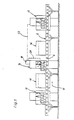
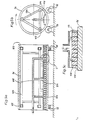
- a device for machining a workpiece made of carbon-containing cast iron, for example mechanically in a known manner to a roughness of about 20 ⁇ m pre-machined cylinder running surfaces of an engine block cast together with the cylinder head is formed by rollers 6 arranged one behind the other.
- rollers 6 arranged one behind the other.
- transport device 8 on.
- the drive of the rollers 6 is not shown in detail, since the structure of the transport device 8 can be of a type known per se.
- alternating reflection stations 12 and mechanical stations 14 are arranged, one of which is shown.
- the passage of the workpiece, not shown in detail, through the cutout of the device shown is such that, according to FIG. workpiece entering from the left into the electrical station 12 th. and there elect in the manner described later. is processed.
- electrochemical processing brings the workpiece from the electrical station 12 to the cleaning station, removes electrolyte residues there and then conveys it to the mechanical station 14. There it becomes mechanical, after which it is moved to the next cleaning station 16 where it is freed of any residues of cutting oils or emulsions, whereupon it is in turn fed to the next electrical station 12.
- FIG. 1 also shows a control unit 18 belonging to the mechanical station 14, in which the diameter of a hole formed in the workpiece is determined in a manner known per se, for example using the dynamic pressure method.
- the measured value is fed to the control unit 18 via a measuring line 20.
- the current intensity and the machining time of the workpiece during subsequent electrochemical removal in the electrical station 12 are determined in the control unit 18, the electrical station 12 being controlled via a control line 22.
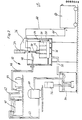
- an electrolyte reservoir 40 is provided, which is connected via a line 42 to a pump 44 which conveys electrolyte into a line 46.
- the line 46 continues within the processing container 24 in a hose 48 which is connected to the hollow electrode holder 50.
- the electrolyte emerging from the electrode 32 and flowing out of the respectively machined bore 30 reaches a return line 52 which opens into an intermediate container 54.
- the electrolyte is conveyed from the intermediate container 54 into a centrifuge 60 by means of a submersible pump 56, which serves to clean the electrolyte. From the centrifuge 60, the electrolyte returns through a line 62 into the electrolyte reservoir 40.
- a styrene supply is provided by a power supply device 64, the positive pole of which is connected to the workpiece 28 via a cable 66 and the negative pole of which is connected to the electrode 32 via a cable 68.
- Electrode 32 which is electrically insulated from hydraulic cylinder 34, is inserted into bore 30 to be machined.
- the electrolyte circuit is activated and the power supply switched on.
- the electrode 32 can stand still or can also rotate or rotate and be translated at the same time as required.
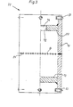
- FIG. 3 shows an electrode 32 cut open in its right half.
- This electrode is an overall cylindrical, self-contained hollow body, the upper end wall 70 of which has a connection opening 74 provided with a thread 72.
- the connection opening 74 serves for screwing in a connection piece, through which the current supply and the electrolyte supply take place, and which is used for fastening the electrode 32 to the hydraulic cylinder 34 (FIG. 2).
- the peripheral wall 76 of the electrode 32 is extended beyond the upper end wall 70 and a lower end wall 78 and carries spacers 80, by means of which the cylindrical outer surface 82 can be adjusted to a defined distance when the electrode is moved into a bore 30 to be machined.
- the spacers 80 are made of insulating material, for example ceramic or plastic.
- the peripheral wall 76 of the electrode 32 is provided in its transverse center plane with electrolyte outlet openings 84.
- the electrolyte outlet openings 84 can be distributed over the lateral surface 82 in accordance with the respective requirements and the desired result.
- the electrolyte outlet openings 84 can be both round and of any other geometry.
- the active surface of the electrode, ie the electrically conductive part of the outer surface 82 can extend over the entire outer surface 82 or can only make up a part of the outer surface 82 due to electrical insulation of part of the surface.
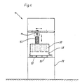
- FIG. 4 shows a mechanical station 14.
- the workpiece 28 rests in a frame 86, which in turn is fastened to a frame 88.
- the frame 86 is provided with adjusting and clamping devices 90 for precisely defined positioning of the workpiece 28.
- a mechanical friction plating tool 92 can be moved on the frame 88 by means of slide guides in all three directions of the space and connected by means of a universal joint 94 to a rotary drive (not shown) which can also be moved up and down.
- the friction plating tool 92 is inserted into one of the bores 30.
- the graphite flakes, exposed mixed crystals or other electrochemical process residues that are exposed during the electrochemical removal are mechanically rubbed and plated, whereby depending on the friction plating tool 92 used, the geometry is also improved and the desired surface roughness and shape can be produced.
- friction p latt istiansstechnikmaschinemaschine 92 are different tools used, such as expandable honing tools similar tools that their processing Generate pressure for example by centrifugal force, rotary brushes with grinding wheels or pure steel or non-ferrous metal rotary brushes.
- expandable honing tools similar tools that their processing Generate pressure for example by centrifugal force, rotary brushes with grinding wheels or pure steel or non-ferrous metal rotary brushes.
- a low processing pressure must be used, with no smearing of the graphite lamellae forming oil pockets and no significant strain hardening of the surface.
- the movement of the friction plating tool 92 can only take place in a rotational, as well as in a rotational and translatory manner.
- a friction plating tool 92 in the form of a honing tool with honing stones made of SiC in ceramic bond and a contact pressure between the largely flat honing stones and the workpiece surface in the order of magnitude of only 10 5 N / m 2 is used, the honing stones take the graphite protruding from the graphite flakes and any residues deposited on the electrochemically machined surface and partially flatten them onto the surface to be machined.
- the graphite together with any deposits is sufficient for a targeted plating of the workpiece surface with graphite and / or M23C6 mixed crystals, preferably in a surface density of 0.5 x 10 -4 to 5 x 10 -4 g / cm 2 .
- the cleaning stations 16 can be omitted.
- the entire device can be constructed from a plurality of stations arranged in series. They can also be designed as a double station, the workpiece being machined alternately in one of the existing mechanical statics and one of the existing electrical stations.
- the alacrolytic removal in the electrostation (s) at the beginning of the fine machining of a workpiece can be greater than towards the end of the machining.
- This also applies to the removal in the mechanical station.
- a charge amount of approximately 5 to 15 As per cm 2 of surface to be processed is advantageously used, this charge amount being implemented for example between 3 and 17 seconds.
- the last mechanical removal advantageously works with an overlap between the tool and the workpiece of only about 1 to 5 ⁇ m. It goes without saying that, after a correspondingly fine purely mechanical pre-processing, a single electrolytic removal and subsequent friction cladding can suffice as the final processing.
- an electrical station is explained as it is used for the machining of cylinder liners for large diesel engines. With such large components, it does not make sense to work with the largest possible electrochemical active area.
- a segment electrode is advantageously used.
- a cylinder liner 96 rests on rollers 98, which can be driven by drums.
- a support frame 100 protrudes into the cylinder liner 96 and is supported on the inner peripheral wall of the cylinder liner 96 by means of rollers 102, so that a carrier 104 fastened to the support frame 100 is aligned relative to the center of the cylinder liner 96.
- a segment electrode 106 is fastened to the carrier 4 and the electrolyte is supplied via lines 108.
- both the cylinder liner 96 and the segment electrode 106 can be moved relative to one another by suitable driving of the frame structure 100.
- the cylinder liner 96 can only be rotated and the segment electrode 106 can only be moved in translation.
- rollers 102 like the segment electrode 106, are advantageously attached to hydraulic cylinders, not shown, with which the support frame 100 can be aligned within the cylinder liner 96 and the gap 112 can be adjusted.
- FIG. 6 shows the lower end of an electrode constructed similarly to the electrode according to FIG. 3 with the peripheral wall 76 and the lower end wall 78, which is formed with a central hole 116.
- a sleeve 123 provided with a slot 118 extends through the hole 116 and is screwed to the end wall 78 by means of a plate 122.
- a bolt 126 whose amplitude of movement is limited by the slot 118 and a pin 128, is movable in the sleeve against the force of a spring 124.
- An electrically insulating cone 129 for example made of ceramic material, is glued to the front end of the bolt, which engages in a conical centering hole in the base of a blind hole to be machined in the workpiece (not shown here) and centers the electrode in the material hole.
- additional stops 132 made of electrically insulating material are provided on the end wall 78.
Landscapes
- Engineering & Computer Science (AREA)
- Chemical & Material Sciences (AREA)
- General Engineering & Computer Science (AREA)
- Mechanical Engineering (AREA)
- Materials Engineering (AREA)
- Metallurgy (AREA)
- Organic Chemistry (AREA)
- Electrochemistry (AREA)
- Chemical Kinetics & Catalysis (AREA)
- Combustion & Propulsion (AREA)
- Electrical Discharge Machining, Electrochemical Machining, And Combined Machining (AREA)
- Electroplating Methods And Accessories (AREA)
- Cylinder Crankcases Of Internal Combustion Engines (AREA)
- Refinement Of Pig-Iron, Manufacture Of Cast Iron, And Steel Manufacture Other Than In Revolving Furnaces (AREA)
- Finish Polishing, Edge Sharpening, And Grinding By Specific Grinding Devices (AREA)
- Other Surface Treatments For Metallic Materials (AREA)
- Solid-Phase Diffusion Into Metallic Material Surfaces (AREA)
Priority Applications (1)
| Application Number | Priority Date | Filing Date | Title |
|---|---|---|---|
| AT82103349T ATE26472T1 (de) | 1981-05-19 | 1982-04-21 | Verfahren zum bearbeiten von oberflaechen eines werkstuecks aus kohlenstoffhaltigem gusseisen sowie vorrichtung zum durchfuehren des verfahrens und aus grauguss bestehender zylinder. |
Applications Claiming Priority (2)
| Application Number | Priority Date | Filing Date | Title |
|---|---|---|---|
| DE3119847A DE3119847C2 (de) | 1981-05-19 | 1981-05-19 | Aus Grauguß bestehender Zylinder einer Kolbenbrennkraftmaschine, Verfahren zum Bearbeiten von Oberflächen eines Werkstücks aus kohlenstoffhaltigem Gußeisen, insbesondere von Zylindern, sowie Vorrichtung zur Durchführung des Verfahrens |
| DE3119847 | 1981-05-19 |
Publications (3)
| Publication Number | Publication Date |
|---|---|
| EP0065645A2 true EP0065645A2 (fr) | 1982-12-01 |
| EP0065645A3 EP0065645A3 (en) | 1984-09-05 |
| EP0065645B1 EP0065645B1 (fr) | 1987-04-08 |
Family
ID=6132670
Family Applications (1)
| Application Number | Title | Priority Date | Filing Date |
|---|---|---|---|
| EP82103349A Expired EP0065645B1 (fr) | 1981-05-19 | 1982-04-21 | Procédé de traitement des surfaces d'une pièce en fonte contenant du carbone et dispositif pour la mise en oeuvre du procédé et cylindre composé de fonte grise |
Country Status (8)
| Country | Link |
|---|---|
| US (1) | US4483755A (fr) |
| EP (1) | EP0065645B1 (fr) |
| JP (1) | JPS581100A (fr) |
| AT (1) | ATE26472T1 (fr) |
| BR (1) | BR8202873A (fr) |
| CA (1) | CA1213244A (fr) |
| DE (2) | DE3119847C2 (fr) |
| ES (2) | ES8304462A1 (fr) |
Cited By (1)
| Publication number | Priority date | Publication date | Assignee | Title |
|---|---|---|---|---|
| EP0169984A3 (en) * | 1984-07-27 | 1987-12-02 | Audi Ag | Method of producing the raceways of cast iron cylinders of a reciprocating engine and device for carrying out the method |
Families Citing this family (17)
| Publication number | Priority date | Publication date | Assignee | Title |
|---|---|---|---|---|
| DE3217818C2 (de) * | 1982-05-12 | 1987-01-29 | Audi AG, 8070 Ingolstadt | Verfahren zum Steuern der Abtragsraten beim abwechselnd elektrochemischen und mechanischen Bearbeiten der Oberflächen von Werkstücken aus kohlenstoffhaltigem Gußeisen |
| JPS6062419A (ja) * | 1983-09-12 | 1985-04-10 | Japax Inc | 全自動ワイヤカツト放電加工装置 |
| DE3537172A1 (de) * | 1985-10-18 | 1987-04-23 | Audi Ag | Verfahren zum bearbeiten einer bohrung sowie vorrichtung zur durchfuehrung des verfahrens |
| JPS6311676U (fr) * | 1986-07-08 | 1988-01-26 | ||
| DE3719796A1 (de) * | 1987-06-13 | 1988-12-22 | Gehring Gmbh Maschf | Verfahren und werkzeug zum bearbeiten von oberflaechen, insbesondere von laufflaechen von verbrennungsmaschinen |
| DE3817259A1 (de) * | 1988-05-20 | 1989-11-23 | Audi Ag | Verfahren und vorrichtung zum bearbeiten von bohrungen |
| JPH0431174U (fr) * | 1990-07-06 | 1992-03-12 | ||
| US5191864A (en) * | 1992-02-03 | 1993-03-09 | Briggs & Stratton Corporation | Engine cylinder bore |
| DE4440713C2 (de) * | 1993-11-23 | 1998-07-02 | Volkswagen Ag | Verfahren zum Herstellen von Gleitflächen an Gußeisenteilen, insbesondere von Zylinderlaufbahnen von Brennkraftmaschinen, sowie Honwerkzeug zur Durchführung des Verfahrens |
| GB2356870A (en) * | 1999-12-01 | 2001-06-06 | Secr Defence | Dissolution of metal structures |
| US6786807B2 (en) | 2002-09-03 | 2004-09-07 | Micromatic Operations, Inc. | Universal coupling for machine tool |
| US6935003B2 (en) * | 2003-02-28 | 2005-08-30 | National University Of Singapore | Compound fabrication process and apparatus |
| JP5283562B2 (ja) * | 2009-05-15 | 2013-09-04 | オリオン機械株式会社 | 冷却装置 |
| DE102009031337A1 (de) | 2009-07-01 | 2011-01-05 | Daimler Ag | Verfahren zum Bearbeiten einer Oberfläche |
| DE102010020227B4 (de) | 2010-05-11 | 2023-10-26 | Ks Kolbenschmidt Gmbh | Verfahren zur Erzeugung einer beliebig gestalteten Geometrie an Kolben von Brennkraftmaschinen und eine Vorrichtung zur Durchführung des Verfahrens |
| CN107345767A (zh) * | 2016-05-06 | 2017-11-14 | 沈阳铝镁设计研究院有限公司 | 一种罐式炉高温煅烧焦的余热回收及冷却装置 |
| CN115979010B (zh) * | 2022-12-31 | 2024-03-19 | 山东金旺装备科技有限公司 | 石油焦罐式煅烧炉余热利用系统 |
Family Cites Families (19)
| Publication number | Priority date | Publication date | Assignee | Title |
|---|---|---|---|---|
| US1844316A (en) * | 1929-05-27 | 1932-02-09 | Simplicity Mfg Company | Boring and grinding machine |
| US1939205A (en) * | 1932-07-15 | 1933-12-12 | Micromatic Hone Corp | Honing tool and fixture |
| DE683262C (de) * | 1935-11-08 | 1939-11-02 | Schmidt Gmbh Karl | Zylinderbuechse fuer Brennkraftmaschinen mit hin und her gehendem Kolben |
| DE733053C (de) * | 1938-11-11 | 1943-03-18 | Willy Franzenburg | Vorrichtung zum Oberflaechendruecken fuer Zylinderlaufbuchsen |
| DE907616C (de) * | 1943-11-07 | 1954-03-25 | Hans Burkhardt Dr Ing | Verfahren zur Bearbeitung von Metallgegenstaenden auf Untermass |
| DE816555C (de) * | 1950-05-12 | 1951-10-11 | Walther Groepler | Verfahren zum Schmieren bzw. Glaetten der Reibflaechen der Spurkraenze an Raedern insbesondere von Schienenfahrzeugen durch UEberziehen mit einem Schmiermittel |
| DE811768C (de) * | 1950-05-31 | 1951-08-23 | Deutsche Edelstahlwerke Ag | Welle, insbesondere Kurbelwelle |
| FR1273987A (fr) * | 1960-09-09 | 1961-10-20 | Jacquet Hispano Suiza Soc | Perfectionnements apportés aux procédés pour l'amélioration des conditions de frottement et de roulement des arbres, roues dentées, etc. |
| US3296747A (en) * | 1964-10-23 | 1967-01-10 | Goetzewerke | Method of and apparatus for honing piston rings |
| US3405049A (en) * | 1964-10-27 | 1968-10-08 | Micromatic Hone Corp | Cylindrical bore sizing and finishing device |
| US3468784A (en) * | 1965-10-13 | 1969-09-23 | Gen Motors Corp | Electrical stock removal apparatus |
| US3499830A (en) * | 1967-11-20 | 1970-03-10 | Cincinnati Milling Machine Co | Apparatus for electrochemically forming and finishing gears |
| US3751346A (en) * | 1971-08-16 | 1973-08-07 | Micromatic Ind Inc | Combined plating and honing method and apparatus |
| DE2229944C3 (de) * | 1972-06-20 | 1975-09-04 | John F. Dipl.-Ing. Elmhurst Ill. Jumer (V.St.A.) | Vorrichtung zum elektrolytischen Polieren der Innenwandung von langgestreckten zylindrischen Behältern |
| DE2531013A1 (de) * | 1975-07-11 | 1977-01-27 | Audi Nsu Auto Union Ag | Verfahren zur herstellung von gleitflaechen aus gusseisen |
| DE2538585A1 (de) * | 1975-08-29 | 1977-03-03 | John F Jumer | Verfahren und vorrichtung zum polieren der innenflaeche eines laenglichen behaelters |
| GB1591804A (en) * | 1977-01-10 | 1981-06-24 | British Petroleum Co | Bearing surface |
| DE2715945C2 (de) * | 1977-04-09 | 1984-04-26 | Henninghaus, Ferdinand, 4000 Düsseldorf | Vorrichtung zum gezogenen Aufbohren rohrförmiger Werkstücke |
| US4312900A (en) * | 1980-06-09 | 1982-01-26 | Ford Motor Company | Method of treating sliding metal contact surfaces |
-
1981
- 1981-05-19 DE DE3119847A patent/DE3119847C2/de not_active Expired
-
1982
- 1982-04-21 EP EP82103349A patent/EP0065645B1/fr not_active Expired
- 1982-04-21 AT AT82103349T patent/ATE26472T1/de not_active IP Right Cessation
- 1982-04-21 DE DE8282103349T patent/DE3276011D1/de not_active Expired
- 1982-05-17 US US06/379,032 patent/US4483755A/en not_active Expired - Fee Related
- 1982-05-18 BR BR8202873A patent/BR8202873A/pt not_active IP Right Cessation
- 1982-05-18 CA CA000403144A patent/CA1213244A/fr not_active Expired
- 1982-05-19 ES ES512373A patent/ES8304462A1/es not_active Expired
- 1982-05-19 JP JP57085648A patent/JPS581100A/ja active Granted
- 1982-05-19 ES ES512374A patent/ES512374A0/es active Granted
Cited By (1)
| Publication number | Priority date | Publication date | Assignee | Title |
|---|---|---|---|---|
| EP0169984A3 (en) * | 1984-07-27 | 1987-12-02 | Audi Ag | Method of producing the raceways of cast iron cylinders of a reciprocating engine and device for carrying out the method |
Also Published As
| Publication number | Publication date |
|---|---|
| ES8304830A1 (es) | 1983-04-01 |
| DE3276011D1 (en) | 1987-05-14 |
| CA1213244A (fr) | 1986-10-28 |
| BR8202873A (pt) | 1983-04-26 |
| ES512373A0 (es) | 1983-03-01 |
| JPS6230279B2 (fr) | 1987-07-01 |
| ATE26472T1 (de) | 1987-04-15 |
| US4483755A (en) | 1984-11-20 |
| DE3119847C2 (de) | 1983-12-29 |
| ES8304462A1 (es) | 1983-03-01 |
| DE3119847A1 (de) | 1983-02-10 |
| EP0065645A3 (en) | 1984-09-05 |
| ES512374A0 (es) | 1983-04-01 |
| EP0065645B1 (fr) | 1987-04-08 |
| JPS581100A (ja) | 1983-01-06 |
Similar Documents
| Publication | Publication Date | Title |
|---|---|---|
| EP0065645B1 (fr) | Procédé de traitement des surfaces d'une pièce en fonte contenant du carbone et dispositif pour la mise en oeuvre du procédé et cylindre composé de fonte grise | |
| DE758779C (de) | Verfahren zum Schuetzen reibungsbeanspruchter Metallflaechen, insbesondere von Zylinderbohrungen | |
| DE102007038050B4 (de) | Verfahren und Vorrichtung zum Schleifen mit elektrolytischer Nachbearbeitung | |
| DE102010020227B4 (de) | Verfahren zur Erzeugung einer beliebig gestalteten Geometrie an Kolben von Brennkraftmaschinen und eine Vorrichtung zur Durchführung des Verfahrens | |
| DE102013109025A1 (de) | Gleitfläche | |
| DE102016114969A1 (de) | Verfahren und Vorrichtung zum elektrolytischen Polieren und Verfahren zum Herstellen einer Kathode | |
| EP0335277B1 (fr) | Procédé et appareil de dépôt sur des surfaces déterminées par voie électrolytique | |
| EP0169984A2 (fr) | Procédé pour la fabrication des surfaces de glissement cylindres en fonte grise d'une machine à piston | |
| DE4440713C2 (de) | Verfahren zum Herstellen von Gleitflächen an Gußeisenteilen, insbesondere von Zylinderlaufbahnen von Brennkraftmaschinen, sowie Honwerkzeug zur Durchführung des Verfahrens | |
| EP2855952A2 (fr) | Structuration par zones de surfaces de glissement | |
| DE102013109043A1 (de) | Gleitfläche | |
| DE3817259A1 (de) | Verfahren und vorrichtung zum bearbeiten von bohrungen | |
| DE3210495A1 (de) | Verfahren zur herstellung von lagerflaechen | |
| DE102012104817B4 (de) | Verfahren und Maschine zum Bearbeiten rotationssymmetrischer Gleitlagerstellen mittels PECM | |
| DE1812312A1 (de) | Verfahren und Werkzeuge zur Aussenrundbearbeitung,insbesondere durch elektrolytisches Schleifen | |
| EP3291939B1 (fr) | Érosion de la denture intérieure sur des extrudeuses planétaires | |
| DE102011084052B4 (de) | Beschichteter Kolbenring mit scharfer Ölabstreifkante | |
| DE3149120C2 (de) | Werkzeug zum Bearbeiten der Oberflächen von Bohrungen in kohlenstoffhaltigem Gußeisen | |
| DE2247956C3 (de) | Werkstück mit galvanisch aufgebrachtem Nickelüberzug und Bad zu dessen Abscheidung | |
| DE102011084051B4 (de) | Beschichteter Kolbenring mit radial zunehmender Schichtdicke und Verfahren zu dessen Herstellung | |
| DE4142952C1 (fr) | ||
| DE2326408C3 (de) | Verfahren zum Erzeugen von Schrägen an Schlitzkanten von Hubkolbenmaschinen-Zylindern | |
| DE3716058A1 (de) | Verfahren zum nacharbeiten von mit verschleissmarken behafteten rotierenden bauteilen | |
| DE10344722B4 (de) | Verfahren zum Herstellen eines wenigstens ein Lagerauge aufweisenden Werkstückes | |
| DE102009031337A1 (de) | Verfahren zum Bearbeiten einer Oberfläche |
Legal Events
| Date | Code | Title | Description |
|---|---|---|---|
| PUAI | Public reference made under article 153(3) epc to a published international application that has entered the european phase |
Free format text: ORIGINAL CODE: 0009012 |
|
| AK | Designated contracting states |
Designated state(s): AT CH DE FR GB IT LI SE |
|
| PUAL | Search report despatched |
Free format text: ORIGINAL CODE: 0009013 |
|
| AK | Designated contracting states |
Designated state(s): AT CH DE FR GB IT LI SE |
|
| 17P | Request for examination filed |
Effective date: 19840926 |
|
| RAP1 | Party data changed (applicant data changed or rights of an application transferred) |
Owner name: AUDI AG |
|
| ITF | It: translation for a ep patent filed | ||
| GRAA | (expected) grant |
Free format text: ORIGINAL CODE: 0009210 |
|
| AK | Designated contracting states |
Kind code of ref document: B1 Designated state(s): AT CH DE FR GB IT LI SE |
|
| REF | Corresponds to: |
Ref document number: 26472 Country of ref document: AT Date of ref document: 19870415 Kind code of ref document: T |
|
| REF | Corresponds to: |
Ref document number: 3276011 Country of ref document: DE Date of ref document: 19870514 |
|
| ET | Fr: translation filed | ||
| PLBE | No opposition filed within time limit |
Free format text: ORIGINAL CODE: 0009261 |
|
| STAA | Information on the status of an ep patent application or granted ep patent |
Free format text: STATUS: NO OPPOSITION FILED WITHIN TIME LIMIT |
|
| 26N | No opposition filed | ||
| ITTA | It: last paid annual fee | ||
| PGFP | Annual fee paid to national office [announced via postgrant information from national office to epo] |
Ref country code: GB Payment date: 19930325 Year of fee payment: 12 |
|
| PGFP | Annual fee paid to national office [announced via postgrant information from national office to epo] |
Ref country code: FR Payment date: 19930406 Year of fee payment: 12 |
|
| PGFP | Annual fee paid to national office [announced via postgrant information from national office to epo] |
Ref country code: SE Payment date: 19930415 Year of fee payment: 12 Ref country code: AT Payment date: 19930415 Year of fee payment: 12 |
|
| PGFP | Annual fee paid to national office [announced via postgrant information from national office to epo] |
Ref country code: CH Payment date: 19930625 Year of fee payment: 12 |
|
| PG25 | Lapsed in a contracting state [announced via postgrant information from national office to epo] |
Ref country code: GB Effective date: 19940421 Ref country code: AT Effective date: 19940421 |
|
| PG25 | Lapsed in a contracting state [announced via postgrant information from national office to epo] |
Ref country code: SE Effective date: 19940422 |
|
| PG25 | Lapsed in a contracting state [announced via postgrant information from national office to epo] |
Ref country code: LI Effective date: 19940430 Ref country code: CH Effective date: 19940430 |
|
| GBPC | Gb: european patent ceased through non-payment of renewal fee |
Effective date: 19940421 |
|
| PG25 | Lapsed in a contracting state [announced via postgrant information from national office to epo] |
Ref country code: FR Effective date: 19941229 |
|
| REG | Reference to a national code |
Ref country code: CH Ref legal event code: PL |
|
| EUG | Se: european patent has lapsed |
Ref document number: 82103349.5 Effective date: 19941110 |
|
| REG | Reference to a national code |
Ref country code: FR Ref legal event code: ST |
|
| PGFP | Annual fee paid to national office [announced via postgrant information from national office to epo] |
Ref country code: DE Payment date: 19960426 Year of fee payment: 15 |
|
| PG25 | Lapsed in a contracting state [announced via postgrant information from national office to epo] |
Ref country code: DE Free format text: LAPSE BECAUSE OF NON-PAYMENT OF DUE FEES Effective date: 19980101 |