EP0065714B1 - Etrier détachable - Google Patents
Etrier détachable Download PDFInfo
- Publication number
- EP0065714B1 EP0065714B1 EP82104189A EP82104189A EP0065714B1 EP 0065714 B1 EP0065714 B1 EP 0065714B1 EP 82104189 A EP82104189 A EP 82104189A EP 82104189 A EP82104189 A EP 82104189A EP 0065714 B1 EP0065714 B1 EP 0065714B1
- Authority
- EP
- European Patent Office
- Prior art keywords
- bracket
- arm
- release
- stirrup
- holding
- Prior art date
- Legal status (The legal status is an assumption and is not a legal conclusion. Google has not performed a legal analysis and makes no representation as to the accuracy of the status listed.)
- Expired
Links
- 230000014759 maintenance of location Effects 0.000 claims abstract 2
- 230000001960 triggered effect Effects 0.000 description 4
- 238000000034 method Methods 0.000 description 3
- 230000006378 damage Effects 0.000 description 2
- 230000007704 transition Effects 0.000 description 2
- 208000010300 Genu Varum Diseases 0.000 description 1
- 238000011109 contamination Methods 0.000 description 1
- 230000000694 effects Effects 0.000 description 1
- 210000000003 hoof Anatomy 0.000 description 1
- 230000001771 impaired effect Effects 0.000 description 1
- 230000009191 jumping Effects 0.000 description 1
- 238000004519 manufacturing process Methods 0.000 description 1
- 239000002245 particle Substances 0.000 description 1
- 230000035939 shock Effects 0.000 description 1
Images

Classifications
-
- B—PERFORMING OPERATIONS; TRANSPORTING
- B68—SADDLERY; UPHOLSTERY
- B68C—SADDLES; STIRRUPS
- B68C3/00—Stirrups
- B68C3/02—Stirrups with side part or sole plate attached to other parts of the stirrup movably, e.g. pivotally
Definitions
- stirrups as part of the saddlery are available in different designs.
- the stirrup is closed in a ring shape and has a U-shaped bracket and a plate-shaped footrest adjoining the two ends of the bracket. Temple and footrest are made in one piece.
- This simple embodiment of the stirrup has the disadvantage that the rider gets stuck with one foot in the stirrup in the event of a fall from the horse under unfavorable circumstances and he is then dragged along for a certain distance. Above all, if the fall occurs off-road, grave and shock injuries are added to any fall injuries if the rider is dragged across the ground and bumps into individual obstacles. Also, because of the close physical proximity to the horse, there is always the danger that it will be hit by a hoof of the moving horse.
- Triggerable stirrups have been proposed to reduce these risks.
- One of these stirrups (DE-C-54 803) has a U-shaped bracket with the usual strap holder.
- the footrest is articulated at one end by means of a hinge joint to one leg of the bracket.
- the other end of the footrest is connected to the other leg of the bracket by means of a releasable holding device.
- the holding device includes a holding rod which has a slightly inclined head with parallel edges. This head is inserted into an equally sloping recess in the associated stirrup leg.
- This also has at its lower end a vertically aligned pin which engages in a corresponding recess in a shoulder on the support rod.
- the holding device also includes a one-armed lever which is rotatably mounted on the stirrup leg and has a horizontally oriented nose which engages in a correspondingly oriented groove of the holding arm.
- the lever has two retaining tabs at its end, which rest resiliently on the retaining arm.
- a trigger device for the holding device is formed by a likewise U-shaped trigger bracket, which is arranged at its two ends by means of a hinge joint on the U-shaped bracket of the stirrup pivotable about a horizontal axis.
- One end of the release bracket is connected to the one-armed lever in a rotationally fixed manner via the pivot pin.
- the arch part of the release bar runs at a certain distance from the stirrup, at least in sections parallel to it.
- the holding device of this stirrup is triggered by the fact that the release bracket is pressed against the stirrup, as a result of which the one-armed lever is pivoted away from the holding rod and thereby its nose is pulled out of the groove of the holding rod.
- the head of the support rod can slide out of the associated recess in the stirrup leg and slide away downward, as a result of which the footplate hinged to it folds downward.
- the release bracket only has a one-way release effect on the holding device of the footplate articulated to the bracket.
- This release bar is on the side of the stirrup on which the tip of the riding boot is located. If, when riding, especially when jumping, after a temporary release of the foot from the stirrup, this twists and the rider then climbs into the stirrup from the wrong side, it can happen that the rider triggers the holding device when he gets deeper into the stirrup. This endangers the rider more than it protects him.
- the trigger mechanism is also far too complicated and complex.
- it has the disadvantage that if, for example, dirt particles adhere to it or are brought up to it voluntarily after a triggering operation in the field, the holding device can only be closed apparently but not properly. This is all the more dangerous since the position of the trigger bracket alone does not provide a reliable indication that the holding device is properly closed. The same danger arises if, unnoticed by the rider, the holding device no longer securely holds the footrest after a partial release movement and is then accidentally fully released.
- the footrest is hingedly connected to one leg of the U-shaped bracket by means of a hinge joint.
- At the other end of the footrest is one in the direction of the longitudinal extension of the footrest
- Aligned holding or supporting pin is present, which is inserted into a notch on the other leg of the U-shaped bracket, the cross-sectional shape of which corresponds to half the cross-section of the pin is present, the cross-sectional shape of the other notch to the full Spigot cross section added.
- the lower part of the leg has a lateral recess into which the folding bracket fits.
- a one-armed lever which is articulated at the transition between the curved part and the straight leg of the bracket and extends approximately parallel to the leg. It has a rag at its lower free end, which lies in front of the folding bracket and holds it in the stop position.
- the lever is held in the folded position by means of a spring catch.
- a one-armed lever is also articulated on the other leg. The ends of both levers are connected to each other by a bracket that serves as a release bracket.
- the release bar has a very low arch height compared to the top of the footrest.
- the low bow height also entails the risk that the rider gets caught on the release bracket with the tail strap or with its buckle.
- the trigger bracket cannot be designed with a larger arc height, because otherwise the central part of the trigger bracket would be at the same height as its swivel joints and a force exerted on the central part would no longer cause any torque.
- the folding bracket which in the folded-up state encloses and holds the holding or carrying pin of the footrest with the associated bracket leg of the U-shaped bracket, namely has a head at its free end, which is constricted neck-shaped at the transition point to the folding bracket before it widens in two concave shoulder lines up to the edges of the folding bracket.
- the recess on the bracket leg that receives the folding bracket continues into a section that is equal to the negative image of the head with the neck and shoulders on the folding bracket.
- the fit of the head in the recess entails the risk that even slight deformations of one or the other part, for example by a notch, can result in the two parts jamming, which the folding out of the folding bracket and thus preventing the stirrup from being triggered.
- the invention specified in claim 1 has for its object to provide a stirrup which is constructed as simply as possible and which offers greater reliability than the known stirrups both in the operational state and in the event of a triggering operation desired in an emergency.
- the holder device has two adjacent and in their longitudinal extent partially overlapping parts, in which there is a flush recess in both parts, in which the retaining tab of the release bracket engages, is a simple and reliable holding device and an equally simple and reliable.Tripping device given.
- the retaining tab on the release bracket engages in the two horizontally aligned recesses of the adjacent parts, the pedal force acting on the footrest is transmitted via the retaining tab directly to the adjacent leg of the bracket, so that the pivot joint of the release bracket is relieved. This flow of force within the holding device also ensures that a release movement is difficult during normal use of the stirrup and thus involuntary releases are not to be feared.
- the holding device When the footrest is relieved, for example in the event of a fall, the holding device is also relieved, so that the triggering process can be carried out all the more easily. Because of the recesses going through on both sides and because the release bracket is arranged in the same plane as the stirrup bracket, the release device can act equally in each of the two actuation directions. It does not matter in which direction a rider got into the stirrup. In addition, this symmetrical arrangement of the release bar in relation to the stirrup bar is immediately clearly visible if after a Release process of the release bracket has not yet been returned to its correct stop position.
- the spring lock supports snapping in because it always presses the release bracket into its central position within a certain adjustment range.
- stirrup By designing the stirrup according to claim 2, mutual guidance and a symmetrical loading of the parts of the holding device and the triggering device is achieved, through their functionality and functional reliability is further improved.
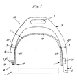
- the triggerable stirrup 12 has a U-shaped bracket 2, a footrest 7 and a trigger bracket 9.
- a belt holder 1 is arranged on the arcuate part of the bracket 2.
- One end of the footrest 7 is articulated by means of a hinge joint 5 to the one leg 13 of the bracket.
- a holding device 15 is arranged between the other leg 14 of the bracket 2 and the other end of the footrest 7.
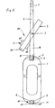
- a holding pin 10 is arranged on the footrest 7. It faces the leg 14 and extends to a certain extent along the end section 16 of the leg 14. Of these parts overlapping in the longitudinal direction, the holding pin 10 is fork-shaped. Its two fork legs 17 and 18 are aligned parallel to each other. They delimit a recess 11 on both sides (FIG. 2).
- the end section 16 is designed as a tongue-shaped extension of the leg 14 (FIG. 2), which is matched to the recess 11 in the fork-shaped holding pin 16.
- the boundary surfaces of the recess 11 and the side surfaces of the tongue-shaped extension 16 are aligned parallel to the relative movement path of the footrest 7.
- the trigger bracket 9 is arranged on the inside of the bracket 2 and, like this, is U-shaped. It has a curved part 19 and two legs 21 and 22. It is pivotally mounted on the legs 13 and 14 of the bracket 2 by means of a pin joint 23. The joint axes 3 of the pivot joints 23 aligned with one another are aligned in the plane of the bracket 2 parallel to the footrest 7.
- One leg 21 has at its end a retaining tab 24 which is angled outward from leg 21.
- the holding tab 24 is arranged on the leg 21 such that it extends into the mutually aligned recesses 8 and 8 'on the holding pin 10 and at the end section 16 in the closed position of the stirrup 12 (FIG. 1).
- the holding pin 10 and the end section 16 with their recesses 8 and 8 ', as well as the holding tab 24 together form the holding device 15 for the footrest 7.
- a spring member with two spring tabs 26 is arranged on the leg 20, which are bent obliquely outwards, so that in the closed state of the stirrup 12 (FIG. 1) are on both sides of the leg 13 of the bracket 2.
- the trigger bracket 9 with its retaining tab 24 and with the spring lock 4 forms a triggering device 26 for the retaining device 15.
Landscapes
- Engineering & Computer Science (AREA)
- Mechanical Engineering (AREA)
- Passenger Equipment (AREA)
- Buckles (AREA)
- Seats For Vehicles (AREA)
- Vehicle Waterproofing, Decoration, And Sanitation Devices (AREA)
- Polishing Bodies And Polishing Tools (AREA)
- Carbon And Carbon Compounds (AREA)
Claims (2)
Priority Applications (1)
| Application Number | Priority Date | Filing Date | Title |
|---|---|---|---|
| AT82104189T ATE23845T1 (de) | 1981-05-16 | 1982-05-13 | Ausloesbarer steigbuegel. |
Applications Claiming Priority (2)
| Application Number | Priority Date | Filing Date | Title |
|---|---|---|---|
| DE19818114515U DE8114515U1 (de) | 1981-05-16 | 1981-05-16 | Ausloesbarer steigbuegel |
| DE8114515U | 1981-05-16 |
Publications (2)
| Publication Number | Publication Date |
|---|---|
| EP0065714A1 EP0065714A1 (fr) | 1982-12-01 |
| EP0065714B1 true EP0065714B1 (fr) | 1986-11-26 |
Family
ID=6727713
Family Applications (1)
| Application Number | Title | Priority Date | Filing Date |
|---|---|---|---|
| EP82104189A Expired EP0065714B1 (fr) | 1981-05-16 | 1982-05-13 | Etrier détachable |
Country Status (3)
| Country | Link |
|---|---|
| EP (1) | EP0065714B1 (fr) |
| AT (1) | ATE23845T1 (fr) |
| DE (2) | DE8114515U1 (fr) |
Families Citing this family (6)
| Publication number | Priority date | Publication date | Assignee | Title |
|---|---|---|---|---|
| AU674627B2 (en) * | 1994-06-27 | 1997-01-02 | Saferider Australia Pty Ltd | Safety stirrup |
| AUPM646194A0 (en) * | 1994-06-27 | 1994-07-21 | Saferider Australia Pty Ltd | Safety stirrup |
| AUPO057096A0 (en) * | 1996-06-21 | 1996-07-11 | Bostock, Hayden | Safety stirrup |
| NL1010561C2 (nl) | 1998-11-16 | 2000-05-17 | Technoflex | Stijgbeugel, alsmede samenstel van riemen voor het berijden van een paard. |
| US7526907B2 (en) | 1999-07-23 | 2009-05-05 | Bostock Developments Pty Ltd | Safety stirrup |
| AUPQ180399A0 (en) | 1999-07-23 | 1999-08-19 | Bostock, Hayden | Safety stirrup |
Family Cites Families (2)
| Publication number | Priority date | Publication date | Assignee | Title |
|---|---|---|---|---|
| DE54803C (de) * | R. FlEK in Charlottenburg, Kirchstrafse 32 III | Sicherheits-Steigbügel, welcher sich nach unten öffnet | ||
| DE238309C (fr) * |
-
1981
- 1981-05-16 DE DE19818114515U patent/DE8114515U1/de not_active Expired
-
1982
- 1982-05-13 EP EP82104189A patent/EP0065714B1/fr not_active Expired
- 1982-05-13 DE DE8282104189T patent/DE3274450D1/de not_active Expired
- 1982-05-13 AT AT82104189T patent/ATE23845T1/de not_active IP Right Cessation
Also Published As
| Publication number | Publication date |
|---|---|
| DE8114515U1 (de) | 1981-10-22 |
| EP0065714A1 (fr) | 1982-12-01 |
| DE3274450D1 (en) | 1987-01-15 |
| ATE23845T1 (de) | 1986-12-15 |
Similar Documents
| Publication | Publication Date | Title |
|---|---|---|
| DE2533470A1 (de) | Skibremse | |
| EP0065714B1 (fr) | Etrier détachable | |
| EP0069753A1 (fr) | Fixation de securite de ski. | |
| CH650687A5 (de) | Skibindung mit einem trittgestell. | |
| DE1491569A1 (de) | Beinorthese | |
| DE19851860B4 (de) | Steigbügel | |
| DE1578841C3 (de) | Fangeinrichtung für Skier | |
| CH646340A5 (de) | Sicherheitsskibindung. | |
| DE69909911T2 (de) | Skischuh | |
| DE8214357U1 (de) | Zusammenklappbare Bügelvorrichtung | |
| DE3611929C2 (de) | Riegelvorrichtung für vorklappbare Rückenlehnen von Sitzen, insbesondere von Fondsitzen für Kraftfahrzeuge | |
| DE2906726C2 (fr) | ||
| DE3306925C2 (de) | Fahrradpedal, insbesondere für ein Rennfahrrad | |
| DE19613432C1 (de) | Vorrichtung für die Längsverstellung eines Kraftfahrzeugsitzes | |
| DE3107035A1 (de) | Fersenstrammer fuer sicherheits-skibindungen | |
| DE2639780A1 (de) | An einem ski oder an einer skibindung montierbare vorrichtung, wie sicherheitsbindung oder skibremse | |
| DE2214502A1 (de) | Einrichtung zum Auslosen einer Sicher heitsskibindung | |
| DE2506924A1 (de) | Skibremse | |
| DE3005978C2 (fr) | ||
| DE69903222T2 (de) | Skischuh | |
| EP0904250B1 (fr) | Selle munie d'etriers maintenus amovibles pour des raisons de securite | |
| DE644553C (de) | Skibindung | |
| EP0842679A1 (fr) | Fixation pour planche à neige | |
| DE3245668A1 (de) | Ausloesende langlaufbindung | |
| DE8705282U1 (de) | Steigbügel |
Legal Events
| Date | Code | Title | Description |
|---|---|---|---|
| PUAI | Public reference made under article 153(3) epc to a published international application that has entered the european phase |
Free format text: ORIGINAL CODE: 0009012 |
|
| AK | Designated contracting states |
Designated state(s): AT CH DE FR GB NL |
|
| 17P | Request for examination filed |
Effective date: 19830530 |
|
| GRAA | (expected) grant |
Free format text: ORIGINAL CODE: 0009210 |
|
| AK | Designated contracting states |
Kind code of ref document: B1 Designated state(s): AT CH DE FR GB LI NL |
|
| REF | Corresponds to: |
Ref document number: 23845 Country of ref document: AT Date of ref document: 19861215 Kind code of ref document: T |
|
| REF | Corresponds to: |
Ref document number: 3274450 Country of ref document: DE Date of ref document: 19870115 |
|
| ET | Fr: translation filed | ||
| PLBE | No opposition filed within time limit |
Free format text: ORIGINAL CODE: 0009261 |
|
| STAA | Information on the status of an ep patent application or granted ep patent |
Free format text: STATUS: NO OPPOSITION FILED WITHIN TIME LIMIT |
|
| 26N | No opposition filed | ||
| PGFP | Annual fee paid to national office [announced via postgrant information from national office to epo] |
Ref country code: AT Payment date: 19930504 Year of fee payment: 12 |
|
| PGFP | Annual fee paid to national office [announced via postgrant information from national office to epo] |
Ref country code: GB Payment date: 19930513 Year of fee payment: 12 |
|
| PGFP | Annual fee paid to national office [announced via postgrant information from national office to epo] |
Ref country code: FR Payment date: 19930526 Year of fee payment: 12 |
|
| PGFP | Annual fee paid to national office [announced via postgrant information from national office to epo] |
Ref country code: NL Payment date: 19930531 Year of fee payment: 12 |
|
| PGFP | Annual fee paid to national office [announced via postgrant information from national office to epo] |
Ref country code: CH Payment date: 19930819 Year of fee payment: 12 |
|
| PG25 | Lapsed in a contracting state [announced via postgrant information from national office to epo] |
Ref country code: GB Effective date: 19940513 Ref country code: AT Effective date: 19940513 |
|
| PG25 | Lapsed in a contracting state [announced via postgrant information from national office to epo] |
Ref country code: LI Effective date: 19940531 Ref country code: CH Effective date: 19940531 |
|
| PG25 | Lapsed in a contracting state [announced via postgrant information from national office to epo] |
Ref country code: NL Effective date: 19941201 |
|
| GBPC | Gb: european patent ceased through non-payment of renewal fee |
Effective date: 19940513 |
|
| NLV4 | Nl: lapsed or anulled due to non-payment of the annual fee | ||
| PG25 | Lapsed in a contracting state [announced via postgrant information from national office to epo] |
Ref country code: FR Effective date: 19950131 |
|
| REG | Reference to a national code |
Ref country code: CH Ref legal event code: PL |
|
| REG | Reference to a national code |
Ref country code: FR Ref legal event code: ST |
|
| PGFP | Annual fee paid to national office [announced via postgrant information from national office to epo] |
Ref country code: DE Payment date: 19950727 Year of fee payment: 14 |
|
| PG25 | Lapsed in a contracting state [announced via postgrant information from national office to epo] |
Ref country code: DE Effective date: 19970201 |