EP0065785B1 - Wellenleiter für Laserstrahlen - Google Patents
Wellenleiter für Laserstrahlen Download PDFInfo
- Publication number
- EP0065785B1 EP0065785B1 EP82104570A EP82104570A EP0065785B1 EP 0065785 B1 EP0065785 B1 EP 0065785B1 EP 82104570 A EP82104570 A EP 82104570A EP 82104570 A EP82104570 A EP 82104570A EP 0065785 B1 EP0065785 B1 EP 0065785B1
- Authority
- EP
- European Patent Office
- Prior art keywords
- mirrors
- mirror
- concave
- waveguide
- beams
- Prior art date
- Legal status (The legal status is an assumption and is not a legal conclusion. Google has not performed a legal analysis and makes no representation as to the accuracy of the status listed.)
- Expired
Links
- CURLTUGMZLYLDI-UHFFFAOYSA-N Carbon dioxide Chemical compound O=C=O CURLTUGMZLYLDI-UHFFFAOYSA-N 0.000 description 10
- 230000015572 biosynthetic process Effects 0.000 description 6
- 229910002092 carbon dioxide Inorganic materials 0.000 description 6
- 239000001569 carbon dioxide Substances 0.000 description 5
- 230000003287 optical effect Effects 0.000 description 5
- 238000000926 separation method Methods 0.000 description 3
- 230000004075 alteration Effects 0.000 description 2
- -1 YAG Chemical compound 0.000 description 1
- 201000009310 astigmatism Diseases 0.000 description 1
- 230000005540 biological transmission Effects 0.000 description 1
- 238000005553 drilling Methods 0.000 description 1
- 230000005284 excitation Effects 0.000 description 1
- 239000007789 gas Substances 0.000 description 1
- 229910052734 helium Inorganic materials 0.000 description 1
- 239000001307 helium Substances 0.000 description 1
- SWQJXJOGLNCZEY-UHFFFAOYSA-N helium atom Chemical compound [He] SWQJXJOGLNCZEY-UHFFFAOYSA-N 0.000 description 1
- 230000002439 hemostatic effect Effects 0.000 description 1
- 238000004519 manufacturing process Methods 0.000 description 1
- 238000005259 measurement Methods 0.000 description 1
- 238000012986 modification Methods 0.000 description 1
- 230000004048 modification Effects 0.000 description 1
- 229910052754 neon Inorganic materials 0.000 description 1
- GKAOGPIIYCISHV-UHFFFAOYSA-N neon atom Chemical compound [Ne] GKAOGPIIYCISHV-UHFFFAOYSA-N 0.000 description 1
- 239000011368 organic material Substances 0.000 description 1
- 239000007787 solid Substances 0.000 description 1
- 230000009466 transformation Effects 0.000 description 1
- 238000003466 welding Methods 0.000 description 1
Images

Classifications
-
- B—PERFORMING OPERATIONS; TRANSPORTING
- B23—MACHINE TOOLS; METAL-WORKING NOT OTHERWISE PROVIDED FOR
- B23K—SOLDERING OR UNSOLDERING; WELDING; CLADDING OR PLATING BY SOLDERING OR WELDING; CUTTING BY APPLYING HEAT LOCALLY, e.g. FLAME CUTTING; WORKING BY LASER BEAM
- B23K26/00—Working by laser beam, e.g. welding, cutting or boring
- B23K26/02—Positioning or observing the workpiece, e.g. with respect to the point of impact; Aligning, aiming or focusing the laser beam
- B23K26/06—Shaping the laser beam, e.g. by masks or multi-focusing
- B23K26/064—Shaping the laser beam, e.g. by masks or multi-focusing by means of optical elements, e.g. lenses, mirrors or prisms
- B23K26/0643—Shaping the laser beam, e.g. by masks or multi-focusing by means of optical elements, e.g. lenses, mirrors or prisms comprising mirrors
-
- B—PERFORMING OPERATIONS; TRANSPORTING
- B23—MACHINE TOOLS; METAL-WORKING NOT OTHERWISE PROVIDED FOR
- B23K—SOLDERING OR UNSOLDERING; WELDING; CLADDING OR PLATING BY SOLDERING OR WELDING; CUTTING BY APPLYING HEAT LOCALLY, e.g. FLAME CUTTING; WORKING BY LASER BEAM
- B23K26/00—Working by laser beam, e.g. welding, cutting or boring
- B23K26/02—Positioning or observing the workpiece, e.g. with respect to the point of impact; Aligning, aiming or focusing the laser beam
- B23K26/06—Shaping the laser beam, e.g. by masks or multi-focusing
- B23K26/0604—Shaping the laser beam, e.g. by masks or multi-focusing by a combination of beams
-
- B—PERFORMING OPERATIONS; TRANSPORTING
- B23—MACHINE TOOLS; METAL-WORKING NOT OTHERWISE PROVIDED FOR
- B23K—SOLDERING OR UNSOLDERING; WELDING; CLADDING OR PLATING BY SOLDERING OR WELDING; CUTTING BY APPLYING HEAT LOCALLY, e.g. FLAME CUTTING; WORKING BY LASER BEAM
- B23K26/00—Working by laser beam, e.g. welding, cutting or boring
- B23K26/02—Positioning or observing the workpiece, e.g. with respect to the point of impact; Aligning, aiming or focusing the laser beam
- B23K26/06—Shaping the laser beam, e.g. by masks or multi-focusing
- B23K26/064—Shaping the laser beam, e.g. by masks or multi-focusing by means of optical elements, e.g. lenses, mirrors or prisms
- B23K26/0648—Shaping the laser beam, e.g. by masks or multi-focusing by means of optical elements, e.g. lenses, mirrors or prisms comprising lenses
-
- B—PERFORMING OPERATIONS; TRANSPORTING
- B23—MACHINE TOOLS; METAL-WORKING NOT OTHERWISE PROVIDED FOR
- B23K—SOLDERING OR UNSOLDERING; WELDING; CLADDING OR PLATING BY SOLDERING OR WELDING; CUTTING BY APPLYING HEAT LOCALLY, e.g. FLAME CUTTING; WORKING BY LASER BEAM
- B23K26/00—Working by laser beam, e.g. welding, cutting or boring
- B23K26/02—Positioning or observing the workpiece, e.g. with respect to the point of impact; Aligning, aiming or focusing the laser beam
- B23K26/06—Shaping the laser beam, e.g. by masks or multi-focusing
- B23K26/0665—Shaping the laser beam, e.g. by masks or multi-focusing by beam condensation on the workpiece, e.g. for focusing
-
- G—PHYSICS
- G02—OPTICS
- G02B—OPTICAL ELEMENTS, SYSTEMS OR APPARATUS
- G02B19/00—Condensers, e.g. light collectors or similar non-imaging optics
- G02B19/0004—Condensers, e.g. light collectors or similar non-imaging optics characterised by the optical means employed
- G02B19/0019—Condensers, e.g. light collectors or similar non-imaging optics characterised by the optical means employed having reflective surfaces only (e.g. louvre systems, systems with multiple planar reflectors)
- G02B19/0023—Condensers, e.g. light collectors or similar non-imaging optics characterised by the optical means employed having reflective surfaces only (e.g. louvre systems, systems with multiple planar reflectors) at least one surface having optical power
-
- G—PHYSICS
- G02—OPTICS
- G02B—OPTICAL ELEMENTS, SYSTEMS OR APPARATUS
- G02B19/00—Condensers, e.g. light collectors or similar non-imaging optics
- G02B19/0033—Condensers, e.g. light collectors or similar non-imaging optics characterised by the use
-
- G—PHYSICS
- G02—OPTICS
- G02B—OPTICAL ELEMENTS, SYSTEMS OR APPARATUS
- G02B6/00—Light guides; Structural details of arrangements comprising light guides and other optical elements, e.g. couplings
- G02B6/10—Light guides; Structural details of arrangements comprising light guides and other optical elements, e.g. couplings of the optical waveguide type
Definitions
- This invention relates to a waveguide for parallel beams emitted from a laser comprising a combination of at least two concave mirrors disposed in series in the beam path, for use in laser-utilizing devices such as laser-utilizing machine tools or laser-utilizing surgical knives.
- a waveguide for a laser beam is obtained by a combination of mirrors and optical lenses.
- flat mirrors have so far been used in the waveguide for the laser surgical knife. Since laser beams are parallel to each other, the transmission of the beams without a change in the diameter of a plurality of parallel beams would seem to be possible by a combination of flat mirrors and the formation of a waveguide in a shape and size as desired.
- the diameter of a "bundle" of such laser beams gradually expands due to the angular expansion of the beam. In the case of a carbon dioxide laser, the diameter of a beam bundle may double within a 2 meter distance.
- EP-A-0 019 447 discloses an optical system comprising three mirrors. Two of the mirrors have a conic elipsoide surface and the third has a conic hyperpoloide surface. Such, this known system comprises a rather complicated mirror arrangement.
- the object of this invention is to provide a waveguide for light beams capable of eliminating focal aberration in both the vertical and transverse directions by a simple combination of mirrors.
- this object is achieved in a waveguide as initially mentioned, which is characterized in that said at least two concave mirrors are spherical mirrors and are arranged in a skew relation such that the normals of the mirrors are laying in different planes.
- the focal length f When light falls or is reflected along the normal of a concave mirror, the focal length f is equal to a half of the radius of curvature R of the concave surface.
- the focal length is different for light falling along a beam axis inclined with respect to the normal passing through the center of the concave surface mirror.
- the focal lengths f are different from each other according to the direction, vertical or transverse, along the sectional plane of the light beam bundle.
- a laser beam bundle is cross-sectionally circular, it is deformed to be elliptical when reflected by the concave surface mirror, that is to say, an aberration appears.
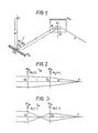
- Fig. 1 shows an arrangement in which mirrors M a and M b are disposed in skew positions at an interval I so that a light beam P is reflected by the first mirror M a and then by M b and a single focus point F results at a point apart by a distance b from the mirror M b .
- the bundle of light beams P is a bundle of laser beams and, therefore, a bundle of parallel beams (a ⁇ ⁇ ).
- the formation of a single image at a point that is, the mirrors M a and M b will be conjugate, only if the following equations hold: positions distant by fl 1 and ft 1 from the mirror Ma respectively.
- the above equation (4) indicates that beams as transverse components whose focus is formed at a position distant from the mirror M a fall on the mirror M b as vertical components and are focused at a point closer to the mirror surface to form an image at a point b.
- Figs. 2 and 3 are illustrative views of light beams corresponding to R 1 (+) and R 2 (+) and to R 1 (-) and R 2 (-) in the concave mirror, respectively.
- the mirror is indicated by a vertical line for simplicity, and the reflected beam is also indicated by a straight line for avoiding difficulties in drawing the actual reflected beams.
- Symbols appearing as convex and concave lenses indicate concave and convex mirrors, respectively.
- Reference characters T W and L w indicate an arrangement in which both mirrors are disposed in skew positions and one in which the normals of both mirrors lie on the same plane, respectively.
- the separation of focal points in the vertical and transverse plane may be eliminated by a combination of two spherical surface mirrors, that is, the parallel beams can be collected at a common focus.
- the light beam system can be diametrally enlarged or narrowed at any arbitrary rate.
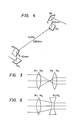
- a combination of mirrors M 1 and M 2 as well as a mirror group M 3 and M 4 are used.
- the mirrors are arranged so that the rear focus of the mirror system of M 1 and M 2 coincides with the front focus of the mirror system of M 3 and M 4 ; and, further, the mirror M 2 , the common focus F o , and the mirror M 3 are all aligned, whereby the parallel beams are narrowed at the focus and then made parallel again.
- the initial diameter B 1 and the final one B 2 can be chosen at any arbitrary ratio.
- the bundle of parallel laser beams can diametrally changed to any size by the use of two pairs of conjugate mirrors.
- the mirrors M 3 and M 4 are concave and disposed askew, but may be replaced by convex ones. In the latter case, the focus of M 1 and M 2 lies farther than the mirrors M 3 and M 4 . That is to say, a point externally dividing the segment between M 2 and M 4 at a ratio of 2:1 is the focus of the mirror system of M 1 and M 2 .
- the mirrors M 3 and M 4 have an imaginary focus, where the radii of curvatures R 3 and R 4 (both are negative real numbers) can be calculated from Eqs. (11) and (12), paying attention to the fact that b is negative.
- Equivalent optical lens system means that the indicated arrangement of mirrors corresponds to an arrangement of convex and concave lenses appropriately combined in the order shown.
- the 19th arrangement is not capable or re-producing strictly parallel beams, but is nonetheless practical.
- Fig. 7 is a schematic structural view of a surgical laser knife to which the present invention is applied.
- beams from a carbon dioxide laser 1 are guided toward the tip of a handpiece 9 by means of a multi-joint reflection system.
- Mirrors M o through M 7 as used conventionally were all flat.
- conjugate mirrors M 1 and M 2 are used so as to reduce the diameter of a bundle of parallel laser beams without deforming the parallism thereof.
- Mirrors M o , M 5 , M 6 and M 7 may be flat.
- the mirrors M 1 and M 2 are disposed in skew arrangement and are concave, whereas M3 and M 4 are also disposed askew, but in a set of concave or convex pairs (corresponding to the first and second examples, respectively in Table 1).
- the pipes 2 through 8 are connected to the mirrors M 1 through M 6 so that adjacent pipes are perpendicular to each other. Since angles of reflection are all adapted to be 45°, the pipes are disposed so as to be perpendicular.
- the present invention is applicable not only to the change of the diameter of a parallel beam bundle, but also to the formation of a non-parallel beam bundle of small diameter by a combination of spherical mirrors capable of forming a common focus.
- the number of mirrors used for formation of one common focus is not always two but may be three or more.
- An image-formation point of the vertical light component reflected by the mirror M 1 is indicated by k 1 and a point of the transverse light component by h 1 , when a measurement of the length from the mirror center and along the direction of travel of the light is performed.
Landscapes
- Physics & Mathematics (AREA)
- Optics & Photonics (AREA)
- Engineering & Computer Science (AREA)
- Plasma & Fusion (AREA)
- Mechanical Engineering (AREA)
- General Physics & Mathematics (AREA)
- Lenses (AREA)
- Laser Beam Processing (AREA)
- Laser Surgery Devices (AREA)
- Light Guides In General And Applications Therefor (AREA)
- Optical Integrated Circuits (AREA)
- Optical Couplings Of Light Guides (AREA)
Claims (3)
Applications Claiming Priority (2)
| Application Number | Priority Date | Filing Date | Title |
|---|---|---|---|
| JP56080593A JPS57195205A (en) | 1981-05-26 | 1981-05-26 | Optical waveguide |
| JP80593/81 | 1981-05-26 |
Publications (2)
| Publication Number | Publication Date |
|---|---|
| EP0065785A1 EP0065785A1 (de) | 1982-12-01 |
| EP0065785B1 true EP0065785B1 (de) | 1986-04-09 |
Family
ID=13722631
Family Applications (1)
| Application Number | Title | Priority Date | Filing Date |
|---|---|---|---|
| EP82104570A Expired EP0065785B1 (de) | 1981-05-26 | 1982-05-25 | Wellenleiter für Laserstrahlen |
Country Status (6)
| Country | Link |
|---|---|
| US (1) | US4586795A (de) |
| EP (1) | EP0065785B1 (de) |
| JP (1) | JPS57195205A (de) |
| AU (1) | AU8419382A (de) |
| CA (1) | CA1179539A (de) |
| DE (2) | DE65785T1 (de) |
Families Citing this family (11)
| Publication number | Priority date | Publication date | Assignee | Title |
|---|---|---|---|---|
| US4588269A (en) * | 1984-07-05 | 1986-05-13 | Eastman Kodak Company | Apparatus which shapes gaussian beams by spherical mirrors |
| LU86037A1 (fr) * | 1985-08-09 | 1987-03-06 | Metallurg Ct Voor De Research | Procede de mise en oeuvre d'un faisceau laser et dispositifs y relatife |
| IL78416A0 (en) * | 1986-04-03 | 1986-08-31 | Uzi Sharon | Laser surgery system |
| JPS63189142A (ja) * | 1987-01-31 | 1988-08-04 | 持田製薬株式会社 | レ−ザメス用ハンドピ−ス |
| DE3709351A1 (de) * | 1987-03-21 | 1988-09-29 | Heraeus Gmbh W C | Strahlfuehrungsoptik fuer laserstrahlung |
| FR2630832B1 (fr) * | 1988-04-29 | 1995-06-02 | Thomson Csf | Systeme de miroirs pour le guidage d'une onde electromagnetique |
| US5206763A (en) * | 1989-05-09 | 1993-04-27 | Macken John A | Corrective optics for rectangular laser beams |
| US4921338A (en) * | 1989-05-09 | 1990-05-01 | Macken John A | Corrective optics for rectangular laser beams |
| JP2720811B2 (ja) * | 1995-03-15 | 1998-03-04 | 住友電気工業株式会社 | レーザ集光方法及び装置 |
| JP2005294393A (ja) * | 2004-03-31 | 2005-10-20 | Fanuc Ltd | レーザ発振器 |
| EP3553880B1 (de) | 2016-12-27 | 2021-11-03 | Huawei Technologies Co., Ltd. | Resonator und kommunikationsvorrichtung |
Citations (1)
| Publication number | Priority date | Publication date | Assignee | Title |
|---|---|---|---|---|
| EP0019447A1 (de) * | 1979-05-16 | 1980-11-26 | Hughes Aircraft Company | Anastigmatisches optisches System aus drei Spiegeln |
Family Cites Families (20)
| Publication number | Priority date | Publication date | Assignee | Title |
|---|---|---|---|---|
| US214501A (en) * | 1879-04-22 | Improvement in telescopes | ||
| US2504383A (en) * | 1945-08-08 | 1950-04-18 | Optische Ind De Oude Delft Nv | Reflecting type telescope having a spherical mirror |
| US2941078A (en) * | 1954-02-16 | 1960-06-14 | Centre Nat Rech Scient | Anastigmatic catoptric device |
| US3112355A (en) * | 1959-11-03 | 1963-11-26 | Karl F Ross | Wide-angle catoptric system |
| US3224330A (en) * | 1961-12-22 | 1965-12-21 | Bell Telephone Labor Inc | Optical reflecting system for redirecting energy |
| US3353893A (en) * | 1967-04-06 | 1967-11-21 | Steven H Bamberger | Rear view automotive periscope utilizing toric mirrors |
| US3762794A (en) * | 1972-04-06 | 1973-10-02 | Bell Telephone Labor Inc | Adjustable beam refocuser and redirector |
| DE2350933C3 (de) * | 1973-10-10 | 1981-10-29 | Winkler & Dünnebier, Maschinenfabrik und Eisengießerei GmbH & Co KG, 5450 Neuwied | Vorrichtung zum Formbrennschneiden einer bewegten Materialbahn mittels eines Laserstrahles |
| JPS5515007B2 (de) * | 1974-03-19 | 1980-04-21 | ||
| US3986767A (en) * | 1974-04-12 | 1976-10-19 | United Technologies Corporation | Optical focus device |
| US3957339A (en) * | 1974-07-12 | 1976-05-18 | Caterpillar Tractor Co. | Laser beam shaping arrangement |
| US3950079A (en) * | 1974-08-19 | 1976-04-13 | Raytheon Company | Steerable catoptric arrangements |
| US4030807A (en) * | 1976-02-09 | 1977-06-21 | General Dynamics Corporation | Optical scanning system with canted and tilted reflectors |
| US4309005A (en) * | 1976-06-17 | 1982-01-05 | Walter G. Finch | Target seeking gyro |
| US4192573A (en) * | 1977-02-14 | 1980-03-11 | The United States Of America As Represented By The Secretary Of The Navy | Variable power attenuator for light beams |
| JPS5410085U (de) * | 1977-06-24 | 1979-01-23 | ||
| US4117319A (en) * | 1977-07-05 | 1978-09-26 | Rockwell International Corporation | Alignment system for lasers |
| US4135787A (en) * | 1977-07-27 | 1979-01-23 | United Technologies Corporation | Unstable ring resonator with cylindrical mirrors |
| NL7904044A (nl) * | 1978-05-31 | 1979-12-04 | Unilever Nv | Werkwijze ter bereiding van homogene, vloeibare compo- sities. |
| US4239341A (en) * | 1978-10-30 | 1980-12-16 | The United States Of America As Represented By The Secretary Of The Army | Unstable optical resonators with tilted spherical mirrors |
-
1981
- 1981-05-26 JP JP56080593A patent/JPS57195205A/ja active Pending
-
1982
- 1982-05-21 CA CA000403486A patent/CA1179539A/en not_active Expired
- 1982-05-25 DE DE198282104570T patent/DE65785T1/de active Pending
- 1982-05-25 DE DE8282104570T patent/DE3270371D1/de not_active Expired
- 1982-05-25 EP EP82104570A patent/EP0065785B1/de not_active Expired
- 1982-05-26 AU AU84193/82A patent/AU8419382A/en not_active Abandoned
-
1984
- 1984-09-24 US US06/654,049 patent/US4586795A/en not_active Expired - Fee Related
Patent Citations (1)
| Publication number | Priority date | Publication date | Assignee | Title |
|---|---|---|---|---|
| EP0019447A1 (de) * | 1979-05-16 | 1980-11-26 | Hughes Aircraft Company | Anastigmatisches optisches System aus drei Spiegeln |
Non-Patent Citations (2)
| Title |
|---|
| Handbook of Optics, p. 2-53 * |
| Longhurst, Geometrical and Physical Optics, p. 370, 371 * |
Also Published As
| Publication number | Publication date |
|---|---|
| CA1179539A (en) | 1984-12-18 |
| JPS57195205A (en) | 1982-11-30 |
| DE65785T1 (de) | 1983-05-11 |
| AU8419382A (en) | 1982-12-02 |
| DE3270371D1 (en) | 1986-05-15 |
| EP0065785A1 (de) | 1982-12-01 |
| US4586795A (en) | 1986-05-06 |
Similar Documents
| Publication | Publication Date | Title |
|---|---|---|
| US4828357A (en) | Apparatus for producing ultra-high power, ultra-high density laser beam | |
| USRE38165E1 (en) | Laser scanning system with reflecting optics | |
| US4281931A (en) | Measuring apparatus comprising light optics utilizing cylindrical focusing glass fiber | |
| JP3089017B2 (ja) | 集束鏡の組合せを有する高出力レーザ装置 | |
| US4248532A (en) | Electro-optical distance-measuring system | |
| DE69922139T2 (de) | Strahlteiler mit versetzten oeffnungen fuer sender/empfaenger in einem optomechanischen lasersystem | |
| US4194808A (en) | Wave guide for surface wave transmission of laser radiation | |
| EP0108618B1 (de) | Vorrichtung zur Projektion eines Laserstrahls in einem Linienmuster | |
| EP0065785A1 (de) | Wellenleiter für Laserstrahlen | |
| US5027377A (en) | Chromatic X-ray magnifying method and apparatus by Bragg reflective planes on the surface of Abbe sphere | |
| US4611883A (en) | Two-dimensional optics element for correcting aberrations | |
| Wynne | Monocentric telescopes for microlithography | |
| US4037943A (en) | Reflection type image forming optical system having a large angle of view | |
| US6698907B1 (en) | Method and device for coupling light sources to a light guide | |
| US4398787A (en) | Optical leverage telecentric scanning apparatus | |
| EP0121069A2 (de) | Reflexionssystem zur Verbesserung der Uniformität eines Lichtbündels | |
| JPS58208717A (ja) | 光輻射発生器と光導波路との結合用装置 | |
| KR950701741A (ko) | 스캐닝 대물렌즈(scanning object lens) | |
| CN106950706A (zh) | 一种用于产生多个焦深的光路装置 | |
| US3592523A (en) | Angle multiplier apparatus | |
| Koga et al. | Development of a portable laser sheet | |
| US3442575A (en) | Optical scanning system | |
| Ronchi | An application of parageometrical optics to the design of a microwave mirror | |
| US4568153A (en) | Binocular telescope | |
| CN117631207A (zh) | 一种激光慢轴准直镜头及激光雷达 |
Legal Events
| Date | Code | Title | Description |
|---|---|---|---|
| PUAI | Public reference made under article 153(3) epc to a published international application that has entered the european phase |
Free format text: ORIGINAL CODE: 0009012 |
|
| AK | Designated contracting states |
Designated state(s): DE FR GB SE |
|
| 17P | Request for examination filed |
Effective date: 19821116 |
|
| EL | Fr: translation of claims filed | ||
| DET | De: translation of patent claims | ||
| GRAA | (expected) grant |
Free format text: ORIGINAL CODE: 0009210 |
|
| AK | Designated contracting states |
Kind code of ref document: B1 Designated state(s): DE FR GB SE |
|
| ET | Fr: translation filed | ||
| REF | Corresponds to: |
Ref document number: 3270371 Country of ref document: DE Date of ref document: 19860515 |
|
| PLBE | No opposition filed within time limit |
Free format text: ORIGINAL CODE: 0009261 |
|
| STAA | Information on the status of an ep patent application or granted ep patent |
Free format text: STATUS: NO OPPOSITION FILED WITHIN TIME LIMIT |
|
| 26N | No opposition filed | ||
| EAL | Se: european patent in force in sweden |
Ref document number: 82104570.5 |
|
| PGFP | Annual fee paid to national office [announced via postgrant information from national office to epo] |
Ref country code: FR Payment date: 19960510 Year of fee payment: 15 |
|
| PGFP | Annual fee paid to national office [announced via postgrant information from national office to epo] |
Ref country code: GB Payment date: 19960516 Year of fee payment: 15 |
|
| PGFP | Annual fee paid to national office [announced via postgrant information from national office to epo] |
Ref country code: SE Payment date: 19960517 Year of fee payment: 15 |
|
| PGFP | Annual fee paid to national office [announced via postgrant information from national office to epo] |
Ref country code: DE Payment date: 19960528 Year of fee payment: 15 |
|
| PG25 | Lapsed in a contracting state [announced via postgrant information from national office to epo] |
Ref country code: GB Effective date: 19970525 |
|
| PG25 | Lapsed in a contracting state [announced via postgrant information from national office to epo] |
Ref country code: SE Effective date: 19970526 |
|
| GBPC | Gb: european patent ceased through non-payment of renewal fee |
Effective date: 19970525 |
|
| PG25 | Lapsed in a contracting state [announced via postgrant information from national office to epo] |
Ref country code: FR Free format text: LAPSE BECAUSE OF NON-PAYMENT OF DUE FEES Effective date: 19980130 |
|
| EUG | Se: european patent has lapsed |
Ref document number: 82104570.5 |
|
| PG25 | Lapsed in a contracting state [announced via postgrant information from national office to epo] |
Ref country code: DE Free format text: LAPSE BECAUSE OF NON-PAYMENT OF DUE FEES Effective date: 19980203 |
|
| REG | Reference to a national code |
Ref country code: FR Ref legal event code: ST |