EP0065793A2 - Bewehrungskonstruktion für Eisenbetongebäude - Google Patents
Bewehrungskonstruktion für Eisenbetongebäude Download PDFInfo
- Publication number
- EP0065793A2 EP0065793A2 EP82200507A EP82200507A EP0065793A2 EP 0065793 A2 EP0065793 A2 EP 0065793A2 EP 82200507 A EP82200507 A EP 82200507A EP 82200507 A EP82200507 A EP 82200507A EP 0065793 A2 EP0065793 A2 EP 0065793A2
- Authority
- EP
- European Patent Office
- Prior art keywords
- elements
- latticework
- reinforcement structure
- sidewall
- structure according
- Prior art date
- Legal status (The legal status is an assumption and is not a legal conclusion. Google has not performed a legal analysis and makes no representation as to the accuracy of the status listed.)
- Granted
Links
- 230000002787 reinforcement Effects 0.000 title claims abstract description 34
- 239000011150 reinforced concrete Substances 0.000 title claims abstract description 8
- 125000006850 spacer group Chemical group 0.000 claims abstract description 40
- XEEYBQQBJWHFJM-UHFFFAOYSA-N Iron Chemical compound [Fe] XEEYBQQBJWHFJM-UHFFFAOYSA-N 0.000 claims abstract description 37
- 238000005266 casting Methods 0.000 claims abstract description 37
- 238000000034 method Methods 0.000 claims abstract description 20
- 229910052742 iron Inorganic materials 0.000 claims abstract description 19
- 239000004567 concrete Substances 0.000 claims abstract description 15
- 238000009432 framing Methods 0.000 claims abstract description 11
- 235000000396 iron Nutrition 0.000 claims description 15
- 239000000203 mixture Substances 0.000 claims description 10
- 238000004873 anchoring Methods 0.000 claims description 9
- 229910000746 Structural steel Inorganic materials 0.000 claims description 4
- 239000002131 composite material Substances 0.000 claims description 3
- 230000003014 reinforcing effect Effects 0.000 description 8
- 230000008901 benefit Effects 0.000 description 7
- 239000004568 cement Substances 0.000 description 6
- 238000010276 construction Methods 0.000 description 6
- 239000000463 material Substances 0.000 description 5
- 239000011398 Portland cement Substances 0.000 description 4
- 229910000831 Steel Inorganic materials 0.000 description 4
- 239000010959 steel Substances 0.000 description 4
- 239000004570 mortar (masonry) Substances 0.000 description 3
- 239000004033 plastic Substances 0.000 description 3
- 229920003023 plastic Polymers 0.000 description 3
- 238000009417 prefabrication Methods 0.000 description 3
- 239000011381 foam concrete Substances 0.000 description 2
- 238000009434 installation Methods 0.000 description 2
- 230000004048 modification Effects 0.000 description 2
- 238000012986 modification Methods 0.000 description 2
- 230000001133 acceleration Effects 0.000 description 1
- 230000009471 action Effects 0.000 description 1
- 239000004411 aluminium Substances 0.000 description 1
- 229910052782 aluminium Inorganic materials 0.000 description 1
- XAGFODPZIPBFFR-UHFFFAOYSA-N aluminium Chemical compound [Al] XAGFODPZIPBFFR-UHFFFAOYSA-N 0.000 description 1
- 239000011449 brick Substances 0.000 description 1
- OSGAYBCDTDRGGQ-UHFFFAOYSA-L calcium sulfate Inorganic materials [Ca+2].[O-]S([O-])(=O)=O OSGAYBCDTDRGGQ-UHFFFAOYSA-L 0.000 description 1
- ZOMBKNNSYQHRCA-UHFFFAOYSA-J calcium sulfate hemihydrate Chemical compound O.[Ca+2].[Ca+2].[O-]S([O-])(=O)=O.[O-]S([O-])(=O)=O ZOMBKNNSYQHRCA-UHFFFAOYSA-J 0.000 description 1
- 230000008859 change Effects 0.000 description 1
- 238000007796 conventional method Methods 0.000 description 1
- 238000010586 diagram Methods 0.000 description 1
- 238000009499 grossing Methods 0.000 description 1
- 239000011507 gypsum plaster Substances 0.000 description 1
- 150000002505 iron Chemical class 0.000 description 1
- 229910052751 metal Inorganic materials 0.000 description 1
- 239000002184 metal Substances 0.000 description 1
- 238000005192 partition Methods 0.000 description 1
- 230000002093 peripheral effect Effects 0.000 description 1
- 230000009467 reduction Effects 0.000 description 1
- 230000000284 resting effect Effects 0.000 description 1
- 239000003351 stiffener Substances 0.000 description 1
- 239000011800 void material Substances 0.000 description 1
- 239000002023 wood Substances 0.000 description 1
Images

Classifications
-
- E—FIXED CONSTRUCTIONS
- E04—BUILDING
- E04G—SCAFFOLDING; FORMS; SHUTTERING; BUILDING IMPLEMENTS OR AIDS, OR THEIR USE; HANDLING BUILDING MATERIALS ON THE SITE; REPAIRING, BREAKING-UP OR OTHER WORK ON EXISTING BUILDINGS
- E04G11/00—Forms, shutterings, or falsework for making walls, floors, ceilings, or roofs
- E04G11/06—Forms, shutterings, or falsework for making walls, floors, ceilings, or roofs for walls, e.g. curved end panels for wall shutterings; filler elements for wall shutterings; shutterings for vertical ducts
- E04G11/08—Forms, which are completely dismantled after setting of the concrete and re-built for next pouring
- E04G11/12—Forms, which are completely dismantled after setting of the concrete and re-built for next pouring of elements and beams which are mounted during erection of the shuttering to brace or couple the elements
- E04G11/16—Forms, which are completely dismantled after setting of the concrete and re-built for next pouring of elements and beams which are mounted during erection of the shuttering to brace or couple the elements with beams placed within the wall
-
- E—FIXED CONSTRUCTIONS
- E04—BUILDING
- E04B—GENERAL BUILDING CONSTRUCTIONS; WALLS, e.g. PARTITIONS; ROOFS; FLOORS; CEILINGS; INSULATION OR OTHER PROTECTION OF BUILDINGS
- E04B1/00—Constructions in general; Structures which are not restricted either to walls, e.g. partitions, or floors or ceilings or roofs
- E04B1/16—Structures made from masses, e.g. of concrete, cast or similarly formed in situ with or without making use of additional elements, such as permanent forms, substructures to be coated with load-bearing material
- E04B1/161—Structures made from masses, e.g. of concrete, cast or similarly formed in situ with or without making use of additional elements, such as permanent forms, substructures to be coated with load-bearing material with vertical and horizontal slabs, both being partially cast in situ
Definitions
- This invention relates to a reinforcing structure for buildings made of reinforced-concrete, such as concrete based on Portland cement having an iron reinforcement, particular for civil buildings, and is also concerned with a building procedure which exploits such a reinforcing structure.
- servicing structure is used herein in the twofold meaning of servicing portion and of a metallic skeleton having supporting functions for the structure which is obtained upon concrete casting.
- the servicing portion that is, the temporary supporting structure for the building to be erected, is composed, as is well known, of the moulds (also called forms or boxings) and of the so-called cribbing which is used to support the moulds and all the loads insisting thereon until the structure becomes self-supporting.
- the iron skeleton instead, is intended to remain embedded within the mass of cement-based or non-cement based concrete to impart to the building the expected resistance properties.
- Buildings of reinforced concrete are usually made according to the conventional run, by installing on the spot the moulds and the attendant cribbing, the latter having the necessary bracings, positioning in the moulds the iron rod reinforcements, usually according to a cage- like pattern, casting the concrete mix, usually in a number of discrete steps, and eventually providing to the removal of the falsework as soon as the structure has become self-supporting, that is, as it has ripened enough. If buildings having a certain size are involved, and/or buildings having many tiers, these operations are carried out repetitively.
- a composite reinforcing structure consisting of a servicing portion and a structural portion proper, said structure essentially comprising an assembly of skeleton elements of iron in latticework arrangement having their relevant interconnection members, spacer elements and sidewall elements which can be latched to said skeleton elements, and removable elements and members for latching the sidewall . elements and the spacer elements to said skeleton elements.
- the structural portion of the reinforcement structure to wit the one which is intended to remain embedded in the concrete casting is essentially composed of the iron latticework skeleton members to be mutually interconnected, said members being also intended to support the servicing portion: the latter portion may comprise said spacer elements, said sidewall elements and said latching elements and members. It cannot be excluded, however, that also the spacer elements and the sidewall elements may remain, totally or only partially, embedded in the casting.
- the method according to this invention starts from the installation of the latticework members to compose a skeleton which is adapted to sustain the servicing portion.
- the basic idea of the invention is not to use the servicing portion to support the iron rod skeleton for the mix to be reinforced within the boxings, but, conversely, to use said skeletal structure in the form of an iron latticework as a supporting struc- cture for the servicing portion or falsework.
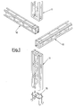
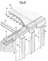
- the reinforcement structure comprises, in the first place, lattice-like iron framing members, such as the horizontal component parts indicated at 10 and the vertical component parts indicated at 11.
- lattice-like iron framing members such as the horizontal component parts indicated at 10 and the vertical component parts indicated at 11.
- These members, 10 and 11 can be connected to each other and secured in correspondence with their ends, by employing common means, not shown, such as screws, bolts and the like, or they can also be welded together so as to make up a latticework framing, generally indicated at 12 in FIGURE 2.
- the latticework frames have, quite advisably, a square or a rectangular cross-sectional contour, but they can have also other sectional contours, if necessary or desired, particularly in correspondence with areas in which two walls meet, such as for example that shown at 13 in FIGURE 2, which has an angular cross-section.
- the latticework elements 10,11,13 are preferably made with steel angle bars having connection straps 20 and the distance between said angle irons must be such as to permit that the casting may satisfactorily fill the interstices.
- the size of the latticework is a function of the width of the walls, the number of floors, and other factors.
- the latticeworks are prepared out of the building yard, in a specialized workshop so that, in the building yard it suffices merely to position and to connect them together.
- anchoring plates and tiebars such as 15 can be used, secured to said foundation.
- Such anchoring plates 15 are embedded in the cast foundations 14 and to such plates the starting horizontal lattice elements 10 are to be secured.
- the framing 12 is mounted by arranging the several vertical elements 11, 13 and horizontal elements 10 which provide the top surface whereon the first floor is to be laid.
- a latticework skeleton is obtained, which is adapted to provide a supporting structure for the servicing portion of the reinforcement structure in question: such skeletal structure is diagrammatically shown in FIGURE 2.
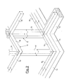
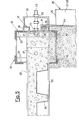
- spacer elements 17 consisting of flat irons which exhibit, on the one side and in correspondence with either end, a spacing projecting section 18 (for example one having a square cross-section) and, in correspondence with the other end, a hooked protrusion 19, as can be clearly seen in FIGURE 3.
- the outer surface of the projection 18 and that of the hooked extension 19 lie on the same plane which is parallel to the plane of member 17.
- the height of the spacer element 17 is such as to permit that it may be mounted flush between two parallel horizontal angle irons of the horizontal latticework elements 10.
- the rods 20 are provided, which are a part of the elements 10 to which nuts 21 are welded in correspondence with specially provided through-holes. Also the spacer elements 17 have corresponding through- bores so as to allow either on of any of the screws 22 to be screwed into the nuts 21 and into lock nuts 23 so as to latch the elements 17 to the tie bars 20 of the horizontal latticework elements 10.
- these elements are the sidewall elements 24 which can be either metallic or also wooden panels, preferably, however, aluminium panels the tops of which are bent at 25 in the fashion of a hook.
- Such sidewall elements 24 are hung by their hooked extensions 25 to the hooks 19 of the spacer elements 17 secured to the horizontal top elements 10 of the latticework whereas their bottom ends rests against the projecting portion 18 of the spacer elements 17 which are secured to the bottom horizontal latticework elements 10 (best seen in FIGURE 3).
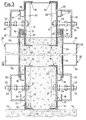
- special vertical stiffening members 26 are provided, consisting of two rectangular steel tubes 27, 28, which are united together at their ends by angle irons 29, 30.
- the top angle iron 29 is bent like a hook at 31 so as to enable also these stiffening elements 26 to be hung to the hooks 19 of the spacer elements 17 secured, in their turn, to the top horizontal latticework elements 10.
- the vertically arranged web of the bottom angle irons 30 of the stiffening members 26 rests against the bottom ends of the sidewall elements 24 and thus also against the projecting portion 18 of the spacer elements 17 which are secured to the bottom horizontal latticework elements 10.
- U-shaped or C-shaped irons 32 are provided, to be laid horizontally, and which have evenly spaced bores formed therethrough for threading screws 22 therein, whereas nuts 33 screwed from the outside to the screws 22 latch the entire assembly to the bottom latticework elements 10 and also to the top elements 10, as can clearly be seen in FIGURE 3.
- the spacer members 17 fulfil the twofold task of sustaining the sidewall elements 24 and the stiffening members 26 in the stage of installation of the servicing portion, and of spacing the external surfaces of the casting from the surfaces of the steel skeleton to be embedded in said casting.
- bracings are required, of any kind, whereas it may be fitting to provide horizontal intermediate stiffening members such as those indicated at 34 in FIGURE 4, which can well be of the same kind as that of the irons 32.
- Such intermediate irons 34 can be connected together pairwise by through- bolts which can be withdrawn as the casting has set.
- the casting can be proceeded with, for example with usual concrete or cellular concrete, preferably involving the entire wall height and, if so desired, with the aid of vibrators.
- the mix is cast until it covers the bottom angles of the top horizontal latticework elements 10 (best seen in FIGURE 3).
- the casting may involve only the peripheral walls or, if so desired, it may be extended also to the partition walls.
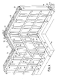
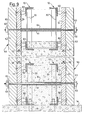
- the floor can be composed of I-irons, 35, with fretlike corrugated sheet irons 36 inserted therebetween 36 (see FIGURES 5 and 6), while using the top horizontal latticework elements 10 of the structure 12 as a resting surface for the ends of the load-bearing beams 35 of the floor concerned.
- Dowels 37 inserted into the ends of the load-bearing beams 35 act as stops for such beams.
- the floor casting can be carried out without any necessity of providing for supporting scaffoldings or intermediate shores.
- the floor can be cast with conventional concrete mixes until the casting top surface is flush with the top webs of the I-irons 35 (FIGURE 5), that which facilitates smoothing of the surface of the casting.
- Each tool 40 comprises a base 41 which can be temporarily secured to the top web of a load bearing I-iron 35 and which carries a supporting member 42 for a screw 43, which, when manipulated at either end, pushes with its other end against the section 39.
- a single tool could also be used, having a consistent length and carrying a plurality of screws 43.
- the tools 40, the sections 39 and the straightedge 38 are withdrawn, also these means thus belong to the servicing portion.
- the space which has been left free by the straightedge 38 can be filled for example with Portland cement mortar, or by the thickness of the floor.
- the reinforcement structure as described hereinbefore with reference to FIGURE 1 to 7 inclusive can be variously modified especially as far as the servicing portion is concerned.
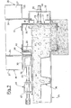
- FIGURE 8 shows an example in which boxingsare provided, generally indicated at 50, which have a wider surface and which have been stiffened beforebnd.
- Such elements 50 are composed, each, of horizontal beams 51 which are held together by mortise and tenon joints such as at 52 and by vertical stiffners 53.
- the beams 51 and the elements 53 can be either wooden or metallic and it is also possible to use wooden posts which have been reinforced by vertical metal pieces. Wooden panels could also be adopted instead of the beams.
- each of said tools comprises a shaft 54 which is freely rotatably mounted in the element 50 and carries on its external portion a crank 55, which is possibly removable, whereas its screw-threaded inner end is screwably affixed to a nut 56 having a bifurcated extension capable of straddling a web of the angle iron of the latticework element 10.
- a spacer bush 37 is inserted by slipping it onto the shaft 54; spacer 57 may be made of a plastics material and a washer 58 is inserted between the crank 55 and the element 50.
- the base portions of the boxings 50 are laid, for example, on the foundation block 14, or, for the upper storeys, on the floor and on a beam belonging to the boxings of the underlying floor, whereafter these elements 50 are anchored, properly spaced by the bushes 57, to the latticework elements 10 by means of said anchoring tools.
- the concrete mix can now be cast and, after that it has hardened, the nut 56 with its forked extension and the spacing bush 57 of each anchoring tool remains embedded in the casting, whereas the other component parts of the anchoring tool are recovered together with the boxing elements 50.
- FIGURE 9 The modification shown in FIGURE 9 is much similar to that shown in FIGURE 8. Also in this case there are mould elements 50 which are composed of horizontal beams or panels 51 and vertical stiffeners 53.
- the posts 51 have, secured thereto, spacers 60 having a tapered form and which jut internally out of the posts and are intended to rest against the vertical webs of the angle irons which make up the horizontal latticework elements 10, as can be clearly seen in FIGURE 9.
- stays 61 are provided with their respective locking nuts 62 and washers 63, said stays being passed through the mould elements 50 which are confrontingly positioned and, between the latter elements, tubes 64 are placed, for example tubes of plastics materials.
- tubes 64 are intended to remain embedded in the casting, whereas it is possible to withdraw, as the casting has set, the stays 61 and the mould elements 50 with the spacers 60 secured thereto.
- the holes which are left in the casting can be closed, for example, with Portland cement mortar.
- a mould consisting of sidewall elements which may be left, either totally, or in part, embedded in the casting, and of stiffening members which can be recovered as the casting has set.
- the sidewall elements or panels which remain attached to the casting may be made of wood, asbestos-cement, plastics materials and other materials.
- the servicing portion described in connection with FIGURES 8 and 9 is particularly suitable for large erecting yards in which large boxings are used, also those comprising a full wall.
- the reinforcement structure according to the present invention and the building procedure using same afford a number of advantages over the conventional art.
- a vital advantage is that inherent in the maximum simplification and rapidity in the erection of the buildings, the possibility of errors during erection being reduced to a degree and without any necessity of having trained personnel available. It is sufficient to have at hand operators who are quickly instructed on the spot and no special erecting yard equipment is required.
- the method of construction is such as to offer a quite reliable stability since the buildings are reinforced by a latticework frame which is continuous and made of steel, to be embedded in the walls: by so doing, the method of construction is particularly suitable also for areas in which earthquakes are often experienced.
- the method of construction is extremely advantageous not only as compared with the conventional erecting methods using load-bearing walls or a reinforced concrete skeleton and brick walls, but is advantageous also as compared with the prefabricated or mixed structures.
- the carpentry work is completely dispensed with, including the positioning of the iron cages, since this work is replaced by the mere assembly of a framing which has been prepared out of the erecting yard and by the assemblage of the servicing portion secured to said framing.
- the walls which are thus obtained are smooth after casting and do not require, for the normal use in a medium class house of moderate price, to be cement rendered or plaster of Paris plastered.
- the method according to the invention affords the advantage that the prefabrication takes place, so to speak, on the spot, the result being to dispense with shipping and positioning bulky and heavy component parts.
- the method combines many an advantage of prefabrication, such as rapidity of erection and reduced labour costs, with the possibility of constructing, in competition with the conventional methods, multy-storey houses in any place, even in remote locations where it is more difficult to find trained workers.
- the method according to the invention conversely, retains the advantage of the conventional procedure of not being bound to any module or standard size, contrary to what occurs in prefabrication.
- the adoption of the construction method according to the invention is, then, particularly suitable for the case of casting made with low-density cellular concrete.
- the method according to the invention is not restricted to the used of cement-based concrete, since it is possible to employ other concrete mixes which are based on materials other than cement.
Landscapes
- Architecture (AREA)
- Engineering & Computer Science (AREA)
- Structural Engineering (AREA)
- Civil Engineering (AREA)
- Electromagnetism (AREA)
- Physics & Mathematics (AREA)
- Mechanical Engineering (AREA)
- Reinforcement Elements For Buildings (AREA)
- Rod-Shaped Construction Members (AREA)
- Working Measures On Existing Buildindgs (AREA)
- Forms Removed On Construction Sites Or Auxiliary Members Thereof (AREA)
- Curing Cements, Concrete, And Artificial Stone (AREA)
- Connector Housings Or Holding Contact Members (AREA)
Priority Applications (1)
| Application Number | Priority Date | Filing Date | Title |
|---|---|---|---|
| AT82200507T ATE17762T1 (de) | 1981-05-07 | 1982-04-29 | Bewehrungskonstruktion fuer eisenbetongebaeude. |
Applications Claiming Priority (2)
| Application Number | Priority Date | Filing Date | Title |
|---|---|---|---|
| IT21571/81A IT1138339B (it) | 1981-05-07 | 1981-05-07 | Armatura per costruzioni in conglomerato armato,come conglomerato cementizio armato,particolarmente per l'edilizia,e metodo di construzione utilizzante tale armatura |
| IT2157181 | 1981-05-07 |
Publications (3)
| Publication Number | Publication Date |
|---|---|
| EP0065793A2 true EP0065793A2 (de) | 1982-12-01 |
| EP0065793A3 EP0065793A3 (en) | 1983-01-05 |
| EP0065793B1 EP0065793B1 (de) | 1986-01-29 |
Family
ID=11183763
Family Applications (1)
| Application Number | Title | Priority Date | Filing Date |
|---|---|---|---|
| EP82200507A Expired EP0065793B1 (de) | 1981-05-07 | 1982-04-29 | Bewehrungskonstruktion für Eisenbetongebäude |
Country Status (9)
| Country | Link |
|---|---|
| US (1) | US4508308A (de) |
| EP (1) | EP0065793B1 (de) |
| AT (1) | ATE17762T1 (de) |
| BR (1) | BR8202559A (de) |
| CA (1) | CA1187712A (de) |
| DE (1) | DE3268760D1 (de) |
| ES (1) | ES8500373A1 (de) |
| GR (1) | GR76020B (de) |
| IT (1) | IT1138339B (de) |
Cited By (3)
| Publication number | Priority date | Publication date | Assignee | Title |
|---|---|---|---|---|
| FR2540166A1 (fr) * | 1983-01-31 | 1984-08-03 | Audrin Didier | Procede d'edification d'un immeuble et equipement pour l'edification d'un tel immeuble |
| GB2150968A (en) * | 1983-12-07 | 1985-07-10 | John F Woodward | Mounting shuttering on self- supporting reinforcement framework |
| WO1989009314A1 (en) * | 1988-03-22 | 1989-10-05 | Biagio Carannante | Process for the construction of buildings |
Families Citing this family (7)
| Publication number | Priority date | Publication date | Assignee | Title |
|---|---|---|---|---|
| US5110084A (en) * | 1988-06-10 | 1992-05-05 | Nissei Plan, Inc. | Form device for cellular concrete and method of making such concrete |
| US5469684A (en) * | 1993-08-10 | 1995-11-28 | Franklin; James W. | Concrete building frame construction method |
| US5460499A (en) * | 1993-08-27 | 1995-10-24 | Franklin; James W. | Concrete building frame construction apparatus |
| US6718723B1 (en) * | 1999-01-09 | 2004-04-13 | Al-Tuhami AbuZeid Al-Tuhami | Method and apparatus for strengthening the concrete elements using prestressing confinement |
| US6709192B2 (en) * | 2000-09-05 | 2004-03-23 | The Fort Miller Group, Inc. | Method of forming, installing and a system for attaching a pre-fabricated pavement slab to a subbase and the pre-fabricated pavement slab so formed |
| KR100454478B1 (ko) * | 2002-04-18 | 2004-10-28 | 한봉길 | 철골철근콘크리트구조를 갖는 고층 건축구조물의 시공방법 |
| CN106545083A (zh) * | 2016-12-27 | 2017-03-29 | 阿博建材(昆山)有限公司 | 一种建筑框架 |
Family Cites Families (17)
| Publication number | Priority date | Publication date | Assignee | Title |
|---|---|---|---|---|
| US1368131A (en) * | 1921-02-08 | Apparatus and method oe constructing walls | ||
| US951120A (en) * | 1908-03-21 | 1910-03-08 | Clarkson P Hockett | Mold for forming walls or buildings of cement or concrete. |
| US1279472A (en) * | 1918-04-15 | 1918-09-17 | Howard E Whiting | Method and apparatus for erecting concrete structures. |
| US1293036A (en) * | 1918-06-27 | 1919-02-04 | Uni Form Company | Apparatus for constructing concrete floors and walls. |
| US1374864A (en) * | 1920-01-20 | 1921-04-12 | Metalform Construction Corp | Adjustable form for concrete structures |
| US1771119A (en) * | 1924-05-10 | 1930-07-22 | David H Hayden | Form |
| US1702659A (en) * | 1927-08-13 | 1929-02-19 | John W Miles | Wall-building form |
| US1936531A (en) * | 1930-08-06 | 1933-11-21 | Weber Charles Gottfried | Concrete form |
| US1949083A (en) * | 1931-10-30 | 1934-02-27 | Roberg Otto | Concrete mold construction |
| US2037965A (en) * | 1933-10-06 | 1936-04-21 | Samuel S Colt | Form support |
| US2050858A (en) * | 1934-01-29 | 1936-08-11 | Universal Form Clamp Company | Beam clamp |
| US2258694A (en) * | 1938-02-25 | 1941-10-14 | Axel G W Wedberg | Form for concrete structures |
| GB617153A (en) * | 1945-03-31 | 1949-02-02 | Farrans Ltd | Improvements in or relating to shuttering for the construction of walls |
| US2455455A (en) * | 1946-12-12 | 1948-12-07 | Paul B West | Prefabricated concrete form |
| FR1058464A (fr) * | 1952-06-17 | 1954-03-16 | Procédé de construction | |
| FR1166760A (fr) * | 1957-02-14 | 1958-11-14 | Procédé de construction d'immeubles économisant la main-d'oeuvre qualifiée et immeubles construits suivant ce procédé | |
| US3899155A (en) * | 1973-10-23 | 1975-08-12 | Edward B Ward | Concrete form panels with hollow reinforcing ribs |
-
1981
- 1981-05-07 IT IT21571/81A patent/IT1138339B/it active
-
1982
- 1982-04-29 AT AT82200507T patent/ATE17762T1/de not_active IP Right Cessation
- 1982-04-29 DE DE8282200507T patent/DE3268760D1/de not_active Expired
- 1982-04-29 EP EP82200507A patent/EP0065793B1/de not_active Expired
- 1982-05-04 US US06/374,794 patent/US4508308A/en not_active Expired - Fee Related
- 1982-05-04 BR BR8202559A patent/BR8202559A/pt unknown
- 1982-05-05 GR GR68074A patent/GR76020B/el unknown
- 1982-05-06 ES ES511981A patent/ES8500373A1/es not_active Expired
- 1982-05-06 CA CA000402387A patent/CA1187712A/en not_active Expired
Cited By (3)
| Publication number | Priority date | Publication date | Assignee | Title |
|---|---|---|---|---|
| FR2540166A1 (fr) * | 1983-01-31 | 1984-08-03 | Audrin Didier | Procede d'edification d'un immeuble et equipement pour l'edification d'un tel immeuble |
| GB2150968A (en) * | 1983-12-07 | 1985-07-10 | John F Woodward | Mounting shuttering on self- supporting reinforcement framework |
| WO1989009314A1 (en) * | 1988-03-22 | 1989-10-05 | Biagio Carannante | Process for the construction of buildings |
Also Published As
| Publication number | Publication date |
|---|---|
| ES511981A0 (es) | 1984-10-01 |
| GR76020B (de) | 1984-08-03 |
| IT8121571A0 (it) | 1981-05-07 |
| EP0065793B1 (de) | 1986-01-29 |
| ATE17762T1 (de) | 1986-02-15 |
| CA1187712A (en) | 1985-05-28 |
| IT1138339B (it) | 1986-09-17 |
| DE3268760D1 (en) | 1986-03-13 |
| US4508308A (en) | 1985-04-02 |
| BR8202559A (pt) | 1983-04-19 |
| EP0065793A3 (en) | 1983-01-05 |
| ES8500373A1 (es) | 1984-10-01 |
Similar Documents
| Publication | Publication Date | Title |
|---|---|---|
| US4211043A (en) | Precast concrete building module form | |
| US20100058687A1 (en) | Method of constructing a multi-storey building using prefabricated modular panels | |
| US20030041555A1 (en) | Construction of high-rise building with large modular units | |
| US6637167B2 (en) | Modular wall construction | |
| US20060096202A1 (en) | Pre-cast panel unibody building system | |
| US4508308A (en) | Reinforcement structure for reinforced-concrete buildings | |
| WO2002066757A9 (en) | A load bearing building panel | |
| JP2915897B1 (ja) | 建築物の躯体施工方法 | |
| RU2552506C1 (ru) | Способ возведения монолитных конструкций зданий и несъёмная универсальная модульная опалубочная система | |
| US4294052A (en) | Prefabricated load bearing structure | |
| JPH1129910A (ja) | コンクリート橋脚の構築方法 | |
| CA2639339A1 (en) | Method of constructing a multi-storey building using prefabricated modular panels | |
| JPH084196A (ja) | 建物用パネル | |
| RU2836225C1 (ru) | Способ возведения монолитных и сборно-монолитных каркасов | |
| JPH10121417A (ja) | コンクリート型枠体とこのコンクリート型枠体を用いたコンクリート構造物の構築方法 | |
| JPH06346471A (ja) | 大型プレキャスト板を用いた鉄筋コンクリート擁壁の施工法 | |
| KR102242175B1 (ko) | 조립식 더블 월 pc 제조 금형 | |
| JPS6334926B2 (de) | ||
| JP2578671B2 (ja) | 柱と梁の構築工法 | |
| AU2004203867B2 (en) | A building system | |
| EA053111B1 (ru) | Способ возведения монолитного и сборно-монолитного каркаса многоэтажного здания | |
| KR20250081648A (ko) | 아파트 피트층 공사방법 | |
| JPH06136821A (ja) | 鉄骨鉄筋コンクリート構造物の構築工法 | |
| CN87103631A (zh) | 复合建筑物的建筑施工法 | |
| CN120649664A (zh) | 花篮螺栓悬挑脚手架预埋套管施工方法及其使用方法 |
Legal Events
| Date | Code | Title | Description |
|---|---|---|---|
| PUAI | Public reference made under article 153(3) epc to a published international application that has entered the european phase |
Free format text: ORIGINAL CODE: 0009012 |
|
| PUAL | Search report despatched |
Free format text: ORIGINAL CODE: 0009013 |
|
| AK | Designated contracting states |
Designated state(s): AT BE CH DE FR GB LU NL SE |
|
| AK | Designated contracting states |
Designated state(s): AT BE CH DE FR GB LI LU NL SE |
|
| 17P | Request for examination filed |
Effective date: 19830609 |
|
| GRAA | (expected) grant |
Free format text: ORIGINAL CODE: 0009210 |
|
| AK | Designated contracting states |
Designated state(s): AT BE CH DE FR GB LI LU NL SE |
|
| PG25 | Lapsed in a contracting state [announced via postgrant information from national office to epo] |
Ref country code: NL Effective date: 19860129 Ref country code: AT Effective date: 19860129 |
|
| REF | Corresponds to: |
Ref document number: 17762 Country of ref document: AT Date of ref document: 19860215 Kind code of ref document: T |
|
| PG25 | Lapsed in a contracting state [announced via postgrant information from national office to epo] |
Ref country code: SE Effective date: 19860131 |
|
| REF | Corresponds to: |
Ref document number: 3268760 Country of ref document: DE Date of ref document: 19860313 |
|
| PG25 | Lapsed in a contracting state [announced via postgrant information from national office to epo] |
Ref country code: LU Free format text: LAPSE BECAUSE OF NON-PAYMENT OF DUE FEES Effective date: 19860430 |
|
| ET | Fr: translation filed | ||
| NLV1 | Nl: lapsed or annulled due to failure to fulfill the requirements of art. 29p and 29m of the patents act | ||
| PLBE | No opposition filed within time limit |
Free format text: ORIGINAL CODE: 0009261 |
|
| STAA | Information on the status of an ep patent application or granted ep patent |
Free format text: STATUS: NO OPPOSITION FILED WITHIN TIME LIMIT |
|
| 26N | No opposition filed | ||
| PG25 | Lapsed in a contracting state [announced via postgrant information from national office to epo] |
Ref country code: GB Effective date: 19890429 |
|
| PG25 | Lapsed in a contracting state [announced via postgrant information from national office to epo] |
Ref country code: LI Effective date: 19890430 Ref country code: CH Effective date: 19890430 Ref country code: BE Effective date: 19890430 |
|
| BERE | Be: lapsed |
Owner name: EDILVELOX S.R.L. Effective date: 19890430 |
|
| GBPC | Gb: european patent ceased through non-payment of renewal fee | ||
| PG25 | Lapsed in a contracting state [announced via postgrant information from national office to epo] |
Ref country code: FR Free format text: LAPSE BECAUSE OF NON-PAYMENT OF DUE FEES Effective date: 19891228 |
|
| REG | Reference to a national code |
Ref country code: CH Ref legal event code: PL |
|
| PG25 | Lapsed in a contracting state [announced via postgrant information from national office to epo] |
Ref country code: DE Effective date: 19900103 |
|
| REG | Reference to a national code |
Ref country code: FR Ref legal event code: ST |
|
| REG | Reference to a national code |
Ref country code: LU Ref legal event code: CNA Free format text: 4830 26 PIAZZA S. NICOLO, 6. I-37121 VERONA, ITALIE |