EP0065942B1 - Einrichtung zum Richten verformter Fahrzeuge oder Fahrzeugteile - Google Patents
Einrichtung zum Richten verformter Fahrzeuge oder Fahrzeugteile Download PDFInfo
- Publication number
- EP0065942B1 EP0065942B1 EP82850117A EP82850117A EP0065942B1 EP 0065942 B1 EP0065942 B1 EP 0065942B1 EP 82850117 A EP82850117 A EP 82850117A EP 82850117 A EP82850117 A EP 82850117A EP 0065942 B1 EP0065942 B1 EP 0065942B1
- Authority
- EP
- European Patent Office
- Prior art keywords
- fastening device
- frame
- straightening
- equipment
- vehicle
- Prior art date
- Legal status (The legal status is an assumption and is not a legal conclusion. Google has not performed a legal analysis and makes no representation as to the accuracy of the status listed.)
- Expired
Links
- 230000000903 blocking effect Effects 0.000 claims description 11
Images

Classifications
-
- B—PERFORMING OPERATIONS; TRANSPORTING
- B21—MECHANICAL METAL-WORKING WITHOUT ESSENTIALLY REMOVING MATERIAL; PUNCHING METAL
- B21D—WORKING OR PROCESSING OF SHEET METAL OR METAL TUBES, RODS OR PROFILES WITHOUT ESSENTIALLY REMOVING MATERIAL; PUNCHING METAL
- B21D1/00—Straightening, restoring form or removing local distortions of sheet metal or specific articles made therefrom; Stretching sheet metal combined with rolling
- B21D1/14—Straightening frame structures
-
- Y—GENERAL TAGGING OF NEW TECHNOLOGICAL DEVELOPMENTS; GENERAL TAGGING OF CROSS-SECTIONAL TECHNOLOGIES SPANNING OVER SEVERAL SECTIONS OF THE IPC; TECHNICAL SUBJECTS COVERED BY FORMER USPC CROSS-REFERENCE ART COLLECTIONS [XRACs] AND DIGESTS
- Y10—TECHNICAL SUBJECTS COVERED BY FORMER USPC
- Y10S—TECHNICAL SUBJECTS COVERED BY FORMER USPC CROSS-REFERENCE ART COLLECTIONS [XRACs] AND DIGESTS
- Y10S72/00—Metal deforming
- Y10S72/705—Vehicle body or frame straightener
-
- Y—GENERAL TAGGING OF NEW TECHNOLOGICAL DEVELOPMENTS; GENERAL TAGGING OF CROSS-SECTIONAL TECHNOLOGIES SPANNING OVER SEVERAL SECTIONS OF THE IPC; TECHNICAL SUBJECTS COVERED BY FORMER USPC CROSS-REFERENCE ART COLLECTIONS [XRACs] AND DIGESTS
- Y10—TECHNICAL SUBJECTS COVERED BY FORMER USPC
- Y10T—TECHNICAL SUBJECTS COVERED BY FORMER US CLASSIFICATION
- Y10T403/00—Joints and connections
- Y10T403/30—Laterally related members connected by latch means, e.g., scaffold connectors
-
- Y—GENERAL TAGGING OF NEW TECHNOLOGICAL DEVELOPMENTS; GENERAL TAGGING OF CROSS-SECTIONAL TECHNOLOGIES SPANNING OVER SEVERAL SECTIONS OF THE IPC; TECHNICAL SUBJECTS COVERED BY FORMER USPC CROSS-REFERENCE ART COLLECTIONS [XRACs] AND DIGESTS
- Y10—TECHNICAL SUBJECTS COVERED BY FORMER USPC
- Y10T—TECHNICAL SUBJECTS COVERED BY FORMER US CLASSIFICATION
- Y10T403/00—Joints and connections
- Y10T403/59—Manually releaseable latch type
- Y10T403/597—Swiveled bolt
Definitions
- the present invention relates to an equipment for straightening deformed vehicles or vehicle parts.
- a vehicle shall be straightened it is fixed to the floor or some type of bench, which supports the vehicle.
- tractive forces can then be applied to the vehicle.
- the distance between points on the vehicle with known positions is checked.
- the present invention starts from a known straightening equipment, manufactured by AB Samefa and described in the brochure Caroliner Mk II, comprising a frame of beams on which the vehicle is supported and fixed.
- One or more straightening devices can be fastened to the frame with the help of a fastening device on the straightening device.
- the fastening device is designed to be able to surround three sides of a frame beam with plates, the device being made with holes in the upper and lower plate for a locking pin which can be put through them and thereby extend along the fourth side of the beam.
- the middle part of the pin is excentrical in relation to the end parts of the pin.
- the fastener can thereby be locked to the beam by turning the pin.
- US-A-4 055 061 describes a straightening apparatus as defined in the precharacterising portion of the following claim, where the fastening device comprises a hooked end rod which grips around the upper, inner corner of the frame beam.
- the fastening device comprises a hooked end rod which grips around the upper, inner corner of the frame beam.
- the fastening device of the invention grips around the lower, inner corner of the frame beam thereby taking up the tractive force applied to the equipment.
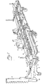
- a measuring equipment can be mounted on the frame 1 which equipment consists of a measuring bridge 6 with measuring slides 7, that are movable in longitudinal direction. On the measuring slides measuring tools 8 are mounted, which can be moved in lateral direction.
- the straightening device comprises a fastening device 10 designed to be able to fasten the straightening device at any place to the frame 1.
- a sleeve 12 is pivoted round a vertical shaft 11, which sleeve can be locked in the fastening device in determined angles with the help of a pin 13.
- An arm 14 is pivoted in the sleeve, so that it can turn round its longitudinal axis. The arm can be locked in certain positions by a pin 15 in a locking device 16.
- a hydraulic cylinder 19 is mounted between the two arms 14 and 17 at some distance from their ends. With the help of the hydraulic cylinder 19 the angle between the arms can be changed, which movement via a chain or a similar element can be applied as tractive force on the vehicle.
- a preferred embodiment of the fastening device is shown in fig. 2 from which it is evident that one of its ends has a U-shaped cross-section by being built-up from an upper 20 and a lower 21 plate and a plate 22, that joins them at some distance from their ends. These plates can be brought into contact with the upper, lower and outer sides of a frame beam 2.
- the fastening device is further provided with a blocking means 23, which can be made to grip round the lower, inner corner of the beam and to be in contact with a lower part of the inner side of the beam and thereby lock the fastening device 10 to the beam 2.
- the blocking means is designed in this way. In order to make the fastening device function well it is absolutely crucial that the blocking means grips round the lower, inner corner. During all normal straightening operations the tractive force attacks the vehicle in such a way that a torsional moment arises round the frame beam 2, which tends to lift the straightening device 9. The movement is very effectively stopped by the mentioned design of the fastening device and the blocking means.
- the blocking means 23 itself can be T-shaped, which permits easy use both from the left and the right side.
- the fastening device 10 can be moved across the frame beam 2.
- the head 24 can then be brought into contact with the lower part of the inner side of the beam 2 by simply turning the blocking means 23 90° so that the head is vertical.
- the blocking means 23 can then be locked in this position with the help of a wedge 25 which is beaten through a hole in the end of the blocking means. If the wedge is designed so that it does not drop off when it is beaten loose by being fitted with a transverse pin or the like in its narrow end, it is possible moreover to obtain the advantage that the wedge, after it has been loosened, turns the blocking means to the free position owing to its weight. This is a convenient design of the blocking means.
Landscapes
- Engineering & Computer Science (AREA)
- Mechanical Engineering (AREA)
- Vehicle Cleaning, Maintenance, Repair, Refitting, And Outriggers (AREA)
- Straightening Metal Sheet-Like Bodies (AREA)
- Body Structure For Vehicles (AREA)
Claims (1)
- Einrichtung zum Richten verformter Fahrzeuge oder Fahrzeugteile, enthaltend einen Rahmen (1) von Trägern (2), auf denen das Fahrzeug befestigt wird, und eine Richtvorrichtung (9), bestehend aus einer Befestigungsvorrichtung (10), die so angeordnet ist, daß sie an jeder Stelle des Rahmens (1) befestigt werden kann, da eines ihrer Enden einen U-förmigen Querschnitt hat, indem es aus einer oberen (20) und einer unteren (21) Platte sowie einer Platte (22) welche sie in einer gewissen Entfernung von ihren Enden miteinander verbindet, aufgebaut ist, wobei diese Anordnung gestattet, daß die Befestigungsvorrichtung (10) mit der oberen, der unteren und den äußeren Seiten eines Rahmenträgers (2) in Berührung gebracht werden kann, und wobei eine Armvorrichtung (14) schwenkbar um eine vertikale Welle (11) in der Befestigungsvorrichtung (10) angebracht und in bestimmten Winkeln blockierbar ist und wobei von der Armvorrichtung (14) Zugkräfte auf das Fahrzeug ausgeübt werden können, dadurch gekennzeichnet, daß die Befestigungsvorrichtung (10) mit einer Blockiervorrichtung (23) versehen ist, die die untere, innere Ecke des Trägers (2) umgreifen kann und die mit einem unteren Teil der Innenseite des Trägers (2) in Berührung gebracht werden kann, um die Befestigungsvorrichtung (10) mit dem Träger (2) zu versperren.
Applications Claiming Priority (2)
| Application Number | Priority Date | Filing Date | Title |
|---|---|---|---|
| SE8103295 | 1981-05-26 | ||
| SE8103295A SE8103295L (sv) | 1981-05-26 | 1981-05-26 | Anordning for att rikta deformerade fordon eller fordonsdelar |
Publications (2)
| Publication Number | Publication Date |
|---|---|
| EP0065942A1 EP0065942A1 (de) | 1982-12-01 |
| EP0065942B1 true EP0065942B1 (de) | 1985-09-11 |
Family
ID=20343923
Family Applications (1)
| Application Number | Title | Priority Date | Filing Date |
|---|---|---|---|
| EP82850117A Expired EP0065942B1 (de) | 1981-05-26 | 1982-05-24 | Einrichtung zum Richten verformter Fahrzeuge oder Fahrzeugteile |
Country Status (4)
| Country | Link |
|---|---|
| US (1) | US4505145A (de) |
| EP (1) | EP0065942B1 (de) |
| DE (1) | DE3266153D1 (de) |
| SE (1) | SE8103295L (de) |
Families Citing this family (19)
| Publication number | Priority date | Publication date | Assignee | Title |
|---|---|---|---|---|
| FR2544070B3 (fr) * | 1983-04-06 | 1985-12-27 | Celette Sa | Appareillage pour le montage d'une carrosserie de voiture sur un marbre de controle |
| EP0148872A1 (de) * | 1983-06-21 | 1985-07-24 | DE FROIDCOURT, Daniel | Vorrichtung zum kontrollieren eines vehikels |
| US4941343A (en) * | 1984-04-30 | 1990-07-17 | Stancato Joe L | Method and apparatus for straightening vehicle bodies and frames |
| FI80392C (fi) * | 1986-05-28 | 1990-06-11 | Autorobot Finland | Riktningsanordning foer bilkaross. |
| FR2599997B1 (fr) * | 1986-06-17 | 1992-09-04 | Celette Sa | Marbre pour la reparation et le controle de carrosseries de vehicules accidentes et equerre de traction qui lui est associee |
| SE454335B (sv) * | 1986-09-03 | 1988-04-25 | Samefa Ab | Karossklamma |
| FR2606303B1 (fr) * | 1986-11-07 | 1991-03-22 | Ollier Aime | Equerre a secteur pour redressage des carrosseries automobiles sur marbre |
| SE461020B (sv) * | 1987-06-30 | 1989-12-18 | Samefa Ab | Riktbaenk |
| FR2621261B1 (fr) * | 1987-10-06 | 1994-05-20 | Sefac | Marbre pour le montage, le controle et la reparation de carrosseries de vehicules automobiles notamment |
| FR2626790B1 (fr) * | 1988-02-10 | 1994-05-20 | Sefac | Equerre de traction adaptable a un marbre, pour le montage, le controle et la reparation des carrosseries de vehicules automobiles |
| FI89684C (fi) * | 1989-12-01 | 1993-11-10 | Autorobot Finland | Riktdon foer bilkarosseri |
| US4959991A (en) * | 1989-12-29 | 1990-10-02 | Car-O-Liner Company | Vehicle chassis support |
| US5415023A (en) * | 1993-08-12 | 1995-05-16 | Hinson; Virgil H. | Universal repair rack truck tie down system |
| SE503368C2 (sv) | 1994-07-06 | 1996-06-03 | Uno Johansson Liner Ab | Anordning för lösbar fastspänning av en draganordning |
| SE520770C2 (sv) * | 2000-08-08 | 2003-08-26 | Car O Liner Ab | Anordning för riktning av fordon, samt lyftbord och dragriktare |
| US7769520B2 (en) * | 2003-10-27 | 2010-08-03 | Ford Global Technologies, Llc | Tractive force map |
| FI117892B (fi) * | 2004-12-07 | 2007-04-13 | Autorobot Finland | Kiinnitin autonkorin oikaisulaitteeseen |
| US7269990B1 (en) * | 2005-04-07 | 2007-09-18 | Michael Espinosa And King's Products, Inc. | Portable frame puller |
| CN103111494B (zh) * | 2013-03-15 | 2015-06-10 | 战家富 | 360度旋转矫正平台 |
Family Cites Families (7)
| Publication number | Priority date | Publication date | Assignee | Title |
|---|---|---|---|---|
| DE2145992A1 (de) * | 1971-09-15 | 1973-03-22 | Germain Celette | Geraet zum richten havarierter fahrzeuge |
| US3921433A (en) * | 1973-12-26 | 1975-11-25 | Walter D Whitney | Apparatus for straightening automobile frames and the like |
| DE2420248A1 (de) * | 1974-04-26 | 1975-11-06 | Tuerke Arthur Gmbh | Universalrichtgeraet |
| US4207681A (en) * | 1976-04-26 | 1980-06-17 | Applied Power Inc. | Vehicle measuring bridge |
| US4055061A (en) * | 1976-04-26 | 1977-10-25 | Applied Power, Inc. | Apparatus for reforming and straightening vehicles |
| DE2834277A1 (de) * | 1978-08-04 | 1980-02-21 | Applied Power Inc | Verankerungsvorrichtung |
| DE2834319A1 (de) * | 1978-08-04 | 1980-02-28 | Applied Power Inc | Richtgeraet |
-
1981
- 1981-05-26 SE SE8103295A patent/SE8103295L/xx unknown
-
1982
- 1982-05-24 EP EP82850117A patent/EP0065942B1/de not_active Expired
- 1982-05-24 US US06/381,637 patent/US4505145A/en not_active Expired - Lifetime
- 1982-05-24 DE DE8282850117T patent/DE3266153D1/de not_active Expired
Non-Patent Citations (1)
| Title |
|---|
| Advertising folder from "SAMEFA" of the Caroliner Mk II system * |
Also Published As
| Publication number | Publication date |
|---|---|
| SE8103295L (sv) | 1982-11-27 |
| US4505145A (en) | 1985-03-19 |
| EP0065942A1 (de) | 1982-12-01 |
| DE3266153D1 (en) | 1985-10-17 |
Similar Documents
| Publication | Publication Date | Title |
|---|---|---|
| EP0065942B1 (de) | Einrichtung zum Richten verformter Fahrzeuge oder Fahrzeugteile | |
| US4322064A (en) | Object-spacing tool and method thereof | |
| CA1064279A (en) | Remotely operable mechanism for disconnecting a pickup unit from a tilt-up concrete wall slab | |
| US4055061A (en) | Apparatus for reforming and straightening vehicles | |
| US4238951A (en) | Portable automobile straightening device | |
| CA2046247A1 (en) | Bench ramps for the repair of damaged vehicle bodyworks and chassis | |
| US4454659A (en) | Adjustable bar carriage for an alignment apparatus | |
| US4088006A (en) | Automotive vehicle body and frame straightening apparatus | |
| US4674730A (en) | Aligning rail ends for welding | |
| HU203998B (en) | Bodywork-levelling device | |
| CZ297694A3 (en) | Apparatus and method of straightening a body of a motor vehicle | |
| EP0249392A2 (de) | Messvorrichtung für Kraftfahrzeug-Karosserie | |
| US4989478A (en) | Turning apparatus | |
| US4282737A (en) | Hand operated bending apparatus and method for metal bar, tubing and the like | |
| US3696653A (en) | Sill clamp for automobiles | |
| US7712716B2 (en) | Adjustable height scaffold combination | |
| US4911419A (en) | Clamping device | |
| EP0085253A1 (de) | Messgeräte für die Ausrichtung einer Fahrzeugkarosserie | |
| EP0104164A1 (de) | Verfahren und vorrichtung zum ausrichten eines verformten elementes eines fahrzeuggestelles | |
| CA1059782A (en) | Form removal device for use in scaffolding | |
| GB2027623A (en) | Straightening apparatus | |
| US4257255A (en) | Apparatus for repairing deformed yieldable structures | |
| US20050183378A1 (en) | Modular structure for maintaining a body part | |
| GB2030207A (en) | Anchoring device | |
| EP0343200A1 (de) | Ausrichtungsvorrichtung für fahrzeugkarosserien |
Legal Events
| Date | Code | Title | Description |
|---|---|---|---|
| PUAI | Public reference made under article 153(3) epc to a published international application that has entered the european phase |
Free format text: ORIGINAL CODE: 0009012 |
|
| 17P | Request for examination filed |
Effective date: 19820607 |
|
| AK | Designated contracting states |
Designated state(s): DE FR GB IT NL |
|
| ITF | It: translation for a ep patent filed | ||
| GRAA | (expected) grant |
Free format text: ORIGINAL CODE: 0009210 |
|
| AK | Designated contracting states |
Designated state(s): DE FR GB IT NL |
|
| REF | Corresponds to: |
Ref document number: 3266153 Country of ref document: DE Date of ref document: 19851017 |
|
| ET | Fr: translation filed | ||
| PLBE | No opposition filed within time limit |
Free format text: ORIGINAL CODE: 0009261 |
|
| STAA | Information on the status of an ep patent application or granted ep patent |
Free format text: STATUS: NO OPPOSITION FILED WITHIN TIME LIMIT |
|
| 26N | No opposition filed | ||
| ITTA | It: last paid annual fee | ||
| PGFP | Annual fee paid to national office [announced via postgrant information from national office to epo] |
Ref country code: GB Payment date: 20010511 Year of fee payment: 20 |
|
| PGFP | Annual fee paid to national office [announced via postgrant information from national office to epo] |
Ref country code: DE Payment date: 20010517 Year of fee payment: 20 |
|
| PGFP | Annual fee paid to national office [announced via postgrant information from national office to epo] |
Ref country code: FR Payment date: 20010530 Year of fee payment: 20 |
|
| PGFP | Annual fee paid to national office [announced via postgrant information from national office to epo] |
Ref country code: NL Payment date: 20010531 Year of fee payment: 20 |
|
| REG | Reference to a national code |
Ref country code: GB Ref legal event code: IF02 |
|
| PG25 | Lapsed in a contracting state [announced via postgrant information from national office to epo] |
Ref country code: GB Free format text: LAPSE BECAUSE OF EXPIRATION OF PROTECTION Effective date: 20020523 |
|
| PG25 | Lapsed in a contracting state [announced via postgrant information from national office to epo] |
Ref country code: NL Free format text: LAPSE BECAUSE OF EXPIRATION OF PROTECTION Effective date: 20020524 |
|
| REG | Reference to a national code |
Ref country code: GB Ref legal event code: PE20 Effective date: 20020523 |
|
| NLV7 | Nl: ceased due to reaching the maximum lifetime of a patent |
Effective date: 20020524 |