EP0066043B1 - Système de freinage de véhicule évitant l'avancement, permettant l'application de freinage additionnel - Google Patents
Système de freinage de véhicule évitant l'avancement, permettant l'application de freinage additionnel Download PDFInfo
- Publication number
- EP0066043B1 EP0066043B1 EP82101738A EP82101738A EP0066043B1 EP 0066043 B1 EP0066043 B1 EP 0066043B1 EP 82101738 A EP82101738 A EP 82101738A EP 82101738 A EP82101738 A EP 82101738A EP 0066043 B1 EP0066043 B1 EP 0066043B1
- Authority
- EP
- European Patent Office
- Prior art keywords
- vehicle
- signal
- output signal
- gate
- certain
- Prior art date
- Legal status (The legal status is an assumption and is not a legal conclusion. Google has not performed a legal analysis and makes no representation as to the accuracy of the status listed.)
- Expired
Links
- 230000000694 effects Effects 0.000 claims description 19
- 230000001419 dependent effect Effects 0.000 claims 17
- 230000001133 acceleration Effects 0.000 claims 3
- 230000000994 depressogenic effect Effects 0.000 description 66
- 230000005540 biological transmission Effects 0.000 description 39
- 238000002485 combustion reaction Methods 0.000 description 20
- 235000014676 Phragmites communis Nutrition 0.000 description 14
- 230000003578 releasing effect Effects 0.000 description 10
- 238000010276 construction Methods 0.000 description 8
- 238000010586 diagram Methods 0.000 description 8
- 239000012530 fluid Substances 0.000 description 4
- 238000000034 method Methods 0.000 description 4
- 230000000717 retained effect Effects 0.000 description 4
- 238000011144 upstream manufacturing Methods 0.000 description 4
- 230000003247 decreasing effect Effects 0.000 description 3
- 239000000446 fuel Substances 0.000 description 3
- 230000003213 activating effect Effects 0.000 description 2
- 238000006243 chemical reaction Methods 0.000 description 2
- 230000007423 decrease Effects 0.000 description 2
- 230000003467 diminishing effect Effects 0.000 description 2
- 230000002035 prolonged effect Effects 0.000 description 2
- 241001296096 Probles Species 0.000 description 1
- 239000000463 material Substances 0.000 description 1
- 238000003825 pressing Methods 0.000 description 1
- 230000001737 promoting effect Effects 0.000 description 1
Images


Classifications
-
- G—PHYSICS
- G05—CONTROLLING; REGULATING
- G05G—CONTROL DEVICES OR SYSTEMS INSOFAR AS CHARACTERISED BY MECHANICAL FEATURES ONLY
- G05G1/00—Controlling members, e.g. knobs or handles; Assemblies or arrangements thereof; Indicating position of controlling members
- G05G1/30—Controlling members actuated by foot
- G05G1/32—Controlling members actuated by foot with means to prevent injury
-
- B—PERFORMING OPERATIONS; TRANSPORTING
- B60—VEHICLES IN GENERAL
- B60T—VEHICLE BRAKE CONTROL SYSTEMS OR PARTS THEREOF; BRAKE CONTROL SYSTEMS OR PARTS THEREOF, IN GENERAL; ARRANGEMENT OF BRAKING ELEMENTS ON VEHICLES IN GENERAL; PORTABLE DEVICES FOR PREVENTING UNWANTED MOVEMENT OF VEHICLES; VEHICLE MODIFICATIONS TO FACILITATE COOLING OF BRAKES
- B60T7/00—Brake-action initiating means
- B60T7/02—Brake-action initiating means for personal initiation
- B60T7/04—Brake-action initiating means for personal initiation foot actuated
-
- B—PERFORMING OPERATIONS; TRANSPORTING
- B60—VEHICLES IN GENERAL
- B60W—CONJOINT CONTROL OF VEHICLE SUB-UNITS OF DIFFERENT TYPE OR DIFFERENT FUNCTION; CONTROL SYSTEMS SPECIALLY ADAPTED FOR HYBRID VEHICLES; ROAD VEHICLE DRIVE CONTROL SYSTEMS FOR PURPOSES NOT RELATED TO THE CONTROL OF A PARTICULAR SUB-UNIT
- B60W10/00—Conjoint control of vehicle sub-units of different type or different function
- B60W10/04—Conjoint control of vehicle sub-units of different type or different function including control of propulsion units
-
- B—PERFORMING OPERATIONS; TRANSPORTING
- B60—VEHICLES IN GENERAL
- B60W—CONJOINT CONTROL OF VEHICLE SUB-UNITS OF DIFFERENT TYPE OR DIFFERENT FUNCTION; CONTROL SYSTEMS SPECIALLY ADAPTED FOR HYBRID VEHICLES; ROAD VEHICLE DRIVE CONTROL SYSTEMS FOR PURPOSES NOT RELATED TO THE CONTROL OF A PARTICULAR SUB-UNIT
- B60W10/00—Conjoint control of vehicle sub-units of different type or different function
- B60W10/10—Conjoint control of vehicle sub-units of different type or different function including control of change-speed gearings
-
- B—PERFORMING OPERATIONS; TRANSPORTING
- B60—VEHICLES IN GENERAL
- B60W—CONJOINT CONTROL OF VEHICLE SUB-UNITS OF DIFFERENT TYPE OR DIFFERENT FUNCTION; CONTROL SYSTEMS SPECIALLY ADAPTED FOR HYBRID VEHICLES; ROAD VEHICLE DRIVE CONTROL SYSTEMS FOR PURPOSES NOT RELATED TO THE CONTROL OF A PARTICULAR SUB-UNIT
- B60W10/00—Conjoint control of vehicle sub-units of different type or different function
- B60W10/18—Conjoint control of vehicle sub-units of different type or different function including control of braking systems
-
- B—PERFORMING OPERATIONS; TRANSPORTING
- B60—VEHICLES IN GENERAL
- B60W—CONJOINT CONTROL OF VEHICLE SUB-UNITS OF DIFFERENT TYPE OR DIFFERENT FUNCTION; CONTROL SYSTEMS SPECIALLY ADAPTED FOR HYBRID VEHICLES; ROAD VEHICLE DRIVE CONTROL SYSTEMS FOR PURPOSES NOT RELATED TO THE CONTROL OF A PARTICULAR SUB-UNIT
- B60W30/00—Purposes of road vehicle drive control systems not related to the control of a particular sub-unit, e.g. of systems using conjoint control of vehicle sub-units
- B60W30/18—Propelling the vehicle
- B60W30/1819—Propulsion control with control means using analogue circuits, relays or mechanical links
-
- Y—GENERAL TAGGING OF NEW TECHNOLOGICAL DEVELOPMENTS; GENERAL TAGGING OF CROSS-SECTIONAL TECHNOLOGIES SPANNING OVER SEVERAL SECTIONS OF THE IPC; TECHNICAL SUBJECTS COVERED BY FORMER USPC CROSS-REFERENCE ART COLLECTIONS [XRACs] AND DIGESTS
- Y10—TECHNICAL SUBJECTS COVERED BY FORMER USPC
- Y10T—TECHNICAL SUBJECTS COVERED BY FORMER US CLASSIFICATION
- Y10T74/00—Machine element or mechanism
- Y10T74/20—Control lever and linkage systems
- Y10T74/20528—Foot operated
Definitions
- the present invention relates to an anti creep braking system for a vehicle according to the precharacterizing portion of claim 1.
- a typical such system provides a device to automatically keep applied the braking force which was used for stopping the vehicle, without requiring the brake pedal to be kept depressed by the vehicle operator, until it is desired to again move the vehicle away from the rest condition, when said braking force is released.
- such an anti creep braking system generally includes a brake pedal braking device, which for instance may be of an electromagnetic type, and which, when the brake pedal has been used to brake the vehicle to a stop, holds the brake pedal at its depressed position until once again it is required to move the vehicle away from rest.
- the control of the engagement and of the releasing of such a brake pedal braking device is also known in various forms.
- the US-PS-4 076 093 discloses in accordance with the preamble of claim 1 an electromagnetic type brake pedal braking device, comprising an electrical control system which controls the selective supply of actuating electrical energy to the electromagnetic type brake pedal braking device to sense this additional stepping on of the brake pedal, and according thereto to temporarily release said electromagnetic type brake pedal braking device, i.e. to temporarily cease the supply of actuating electrical energy thereto, in order to allow the abovementioned further depression of said brake pedal.
- the electrical control system recommences the supply of actuating electrical energy to the electromagnetic type brake pedal braking device, in order to keep the brake pedal fixed at the new second depressed position.
- this complicated form of action required from the electrical control system has made such a control system complicated, with the attendant disadvantages of high cost, high bulk, unreliability, and difficulty in servicing.
- a further set of difficulties that have arisen with regard to such a brake pedal braking device are connected with the proper times to supply activating electrical energy to, and to cease said supply of activating electrical energy to, the electromagnetic type brake pedal braking device.
- a control system which controls such a brake pedal braking device to start said supply of actuating electrical energy to the electromagnetic type brake pedal braking device, when it is determined that the vehicle has been braked substantially to rest, and this is typically done by sensing the revolution speed of at least one wheel of the vehicle and, when said revolution speed becomes very low or substantially zero and at the same time the throttle or accelerator pedal of the vehicle is at substantially idling position, commencing said supply of actuating electrical energy to the electromagnetic type brake pedal braking device.
- an anti creep braking system for a vehicle comprising the features of the characterizing portion of claim 1.
- the provision of the one way clutch in combination with the power device and the control system ensures a permanent load on the brake pedal as long as it is needed, even when it is changed from one depressed state to another, more depressed state.
- Fig. 1 is a part perspective part diagrammatical view, showing an embodiment of the anti creep braking system according to the present invention, and particularly showing the mechanical parts thereof in detail, the control system for said embodiment being shown as a block in this figure.
- the reference numeral 1 denotes a brake pedal for applying the brakes of an automotive vehicle, not particularly shown, and this brake pedal 1 is pivoted via a pivot shaft 2 which is part of a braking force generation system, to the body, also not shown, of this automotive vehicle.
- a braking force transmission member 3 which is part of the braking force generation system, too, which leads in the rightwards direction in the figure to transmit braking force to a per se conventional braking arrangement such as a master cylinder device or the like, diagrammatically shown by a block 60, belonging to the braking force generation system.
- the master cylinder device or the like when the brakes are applied, produces more and more application of the brakes of the vehicle, i.e. produces more and more braking effect for the vehicle, according as the force applied to the brake pad of the brake pedal 1 to rotate it in the anticlockwise direction in Fig. 1 is greater and greater.
- a pivot pin 4 to which one end of a connecting link 5 is pivotally mounted.
- the other end of this connecting link 5 is pivotally connected, via a yoke member 6 formed on it and a pin 7, to a lower (in the figure) protuberance of an internal rack member 8 incorporated the anti creep vehicle braking system.
- an upper (in the figure) protuberance of this internal rack member 8 is pivoted, via a pivot pin 9, to a body, i.e. a bracket member 10 of the braking system which is fixed to the automotive vehicle.
- the internal rack member 8 is formed with a curved slot 11, and on the side of this curved slot 11 remote from the pin 9, in this shown first preferred embodiment, there is formed a sector gear or rack 12, which is of the general form of a sector of a circle whose center is the central axis of the pin 9.
- a sector gear or rack 12 which is of the general form of a sector of a circle whose center is the central axis of the pin 9.
- Fig. 2 which is a sectional view through the mechanism shown in Fig. 1 taken along a plane shown by the arrows II-II in Fig. 1, there is located a pinion 21, which is fixedly mounted on an input member in form of a pinion shaft 20 which extends in the direction parallel to the pivot shaft 2 of the brake pedal 1 and to the pin 9.
- an electromagnetic brake assembly power device 13 which will now be described.
- An electromagnetic coil 14 is fixedly mounted to said bracket member 10, and within the cylindrical inner surface of this electromagnetic coil 14 there is disposed a roller bearing 15 which comprises a multitude of needle rollers.
- a roller bearing 15 which comprises a multitude of needle rollers.
- an output member in form of a sleeve member 16 which can therefore rotate freely within the electromagnetic coil 14 and with respect to the bracket member 10, and which can also move axially to and fro, to the left and the right in Fig. 2, with respect to said electromagnetic coil 14, to a certain extent.
- the left hand end in the figure of this sleeve member 16 is formed as a disk shaped flange 17, to which there is fixedly attached an armature 18, which in fact is formed as a flat annulus, and which is made of a magnetically attractable material.
- This one way clutch 19 may be a roller clutch or the like, and is constructed and mounted in such a sense that, when the rotation of the sleeve member is fixed by, as explained above, actuating electrical energy being supplied to said electromagnetic coil 14 and said electromagnetic coil 14 attracting the armature 18 and squeezing said armature 18 against the body of said electromagnetic coil 14, so that said armature 18 and said flange 17 and said sleeve member 16 are not free to rotate at all with respect to said electromagnetic coil 14 and said bracket member 10 on said needle roller bearing 15 but are fixed with respect thereto, then the pinion shaft 20 and the pinion 21 fixed thereto are free to move in the anticlockwise direction as seen in Fig. 1, but are .
- the electromagnetic coil 14 is selectively supplied with said supply of actuating electrical energy, so as selectively as explained above either to allow the pinion 21 to move in either rotational direction, or to prevent the pinion 21 from moving in the clockwise rotation direction only, from a control system 23, which will be explained in detail with respect to several possible constructions thereof later.
- a control system 23 supplies actuating electrical energy to the electromagnetic coil 14, so as to prevent the pinion 21 from moving in the clockwise rotational direction only, when the automotive vehicle to which this braking system is fitted is braked to a halt and kept in a forward driving range of an automatic transmission fitted thereto, such as "D" range, while waiting for a traffic signal or the like.
- the brake pedal 1 is depressed so as to first brake the vehicle, by the foot of the operator of the vehicle pressing the brake pad of said brake pedal 1, and then said brake pedal 1 rotates in the anticlockwise direction in Fig. 1 about the pivot shaft 2, and thus the braking force transmission member 3 is impelled rightwards in Fig. 1, so as to cause the above mentioned braking system of the vehicle including a brake master cylinder or the like to apply braking effect for the vehicle, in a per se well known way.
- control system 23 decides that the vehicle has been braked to rest-and this decision may be made according to a variety of criteria, as will be explained in detail with respect to the particular functioning of said control system 23 in the various particular embodiments to be described later-then said control system 23 starts to supply electrical current to the electromagnetic coil 14, so that said electromagnetic coil 14 starts to attract the armature 18 and pulls said armature 18 against itself, effectively thereby preventing the rotation of said armature 18 and the flange 17 and the sleeve member 16 formed integrally therewith, with respect to the bracket member 10 and the body of the automotive vehicle.
- control system 23 decides that it is appropriate to release the above described anti creep braking effect which is being provided for the vehicle (and this decision will again be explained in detail with respect to the particular functioning of said control system 23 in the varius particular embodiments t be described later; for instance, this releasing may be performed when the accelerator pedal of the vehicle is depressed), then said control system 23 ceases supplying electrical current to the electromagnetic coil 14, so that said electromagnetic coil 14 ceases to attract the armature 18 and ceases to pull said armature 18 against itself, ceasing thus to prevent the rotation of said armature 18 and the flange 17 and the sleeve member 16 formed integrally therewith with respect to the bracket member 10 and the body of the automotive vehicle.
- the particular advantage of the shown construction incorporating the one way clutch 19 is that additional stepping on of the brake pedal 1 can be performed without releasing the electromagnetic brake power device 13 by temporarily interrupting the supply of actuating electrical energy thereto, and the brake pedal is automatically retained in this additionally stepped on position.
- the control system 23 which selectively supplies said actuating electrical energy for the electromagnetic brake power device 13 can be made much more simple than has been the case in the prior art, because it is possible to keep the electromagnetic brake always activated, i.e. supplied with actuating electrical energy, when the braking force of the brake pedal 1 is to be retained. Further, this results in an increase in reliability and durability of the braking system, and also reduces its cost and bulk.
- control system 23 which selectively supplies actuating electrical energy to the electromagnetic coil 14 of the electromagnetic brake power device 13 will be explained.
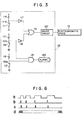
- This control system 23 is shown in block diagram form in Fig. 3, along with the electromagnetic brake 13 which is schematically shown by a block.
- a driver circuit 120 incorporated in said control system 23, which incorporates an electrical power supply starting circuit and an electrical power cutting off circuit, neither of which are particularly shown in the figures.
- This electrical power supply starting circuit functions so as to commence the supply of actuating electrical energy to the electromagnetic brake 13, according to various criteria relating to the operating condition of the vehicle which are sensed by various sensors which are not shown in the figure.
- said electrical power supply starting circuit may start to provide supply of actuating electrical energy to said electromagnetic brake 13 when the rotation speed of a wheel of the vehicle is lower than a certain predetermined speed and additionally, the brake pedal of the vehicle is heavily stepped upon.
- said electrical power supply starting circuit may be similar to the relevant parts of the third preferred control system of the braking system shown in Fig. 5, or of the fourth preferred control system of the braking system shown in Fig. 7.
- the electrical power cutting off circuit within the driver circuit 120 functions so as to cut off the supply of actuating electrical energy to the electromagnetic brake 13, according to the selective supply to said electrical power cutting off circuit of a 1 signal or of a 0 signal, this so called cutoff signal as will be seen later being provided from the output of an OR gate 119 which belongs to an accelerator pedal operative sensing system or a parking range sensing system. And the rest of the control system 23 shown in Fig. 3, i.e. the part upstream in the control sense of the point where said so called cutoff signal enters the driver circuit 120, functions so as to generate this cutoff signal.
- This cutoff signal generating part of said control system 23 operates according to the signals from three sensors incorporated therein: an accelerator pedal sensor switch 111, which is open when the accelerator pedal (not shown) which controls the internal combustion engine of the vehicle is not depressed at all, and which is closed when said accelerator pedal is depressed by even a small amount from the non depressed condition; a parking range sensor switch 112 which is closed when the automatic transmission (not shown) of the vehicle is put into parking or "P" range, and which is open when said automatic transmission is put into any range other than said parking or "P” range; and a seat sensor switch 113, which is provided in or near the driver's seat (not shown) in which the driver sits when he is operating the vehicle, and which is closed when a driver is sitting in said driver's seat, while it is open when no driver is sitting in said driver's seat.
- an accelerator pedal sensor switch 111 which is open when the accelerator pedal (not shown) which controls the internal combustion engine of the vehicle is not depressed at all, and which is closed when said accelerator pedal
- One terminal of each one of the accelerator pedal sensor switch 111, the parking range sensor switch 112, and the seat sensor switch 113 is connected to ground, and the other terminal 111 a of the accelerator pedal sensor switch 111 is connected via a resistive element 114 to a power source such as the battery of the vehicle, the other terminal 112a of the parking range sensor switch 112 is connected via a resistive element 115 to said power source, and the other terminal 113a of the seat sensor switch 113 is similarly connected via a resistive element 116 to said power source.
- the voltage signal present at said other terminal 111a of said accelerator pdeal sensor switch 111 is a 1 or 0 signal (taking ground potential as a 0 signal) indicating respectively whether said accelerator pedal sensor switch 111 is open or closed, i.e. respectively whether the accelerator pedal which controls the internal combustion engine of the vehicle is not depressed at all, or is depressed by even a small amount from the non depressed condition;
- the voltage signal present at said other terminal 112a of said parking range sensor switch 112 is a 1 or 0 signal indicating respectively whether said parking range sensor switch 112 is open or closed, i.e.
- the voltage signal present at said other terminal 113a of said seat sensor switch 113 is a 1 or 0 signal indicating respectively whether said seat sensor switch 113 is open or closed, i.e. respectively whether no driver is sitting in said driver's seat, or a driver is sitting in said driver's seat.
- Said other terminal 111a of said accelerator pedal sensor switch 111 is connected to the input of a NOT gate 117, which belongs to the accelerator pedal operation sensing system, and said said other terminal 112a of said parking range sensor switch 112 is connected to the input of another NOT gate 118, which belongs to the parking range sensing system and is also connected to one input of an AND gate 121, the other input of which is fed from said other terminal 113a of said seat sensor switch 113.
- the outputs of the two NOT gates 117 and 118 are connected to the two inputs of the previously mentioned OR gate 119, the output of which is, as stated before, fed to the electrical power cutting off circuit included within the driver circuit 120 as said cutoff signal.
- the output of said AND gate 121 is connected to an alarm buzzer 122, which produces a loud warning sound when it is fed with a 1 signal, but which produces no sound as long as it is fed with a 0 signal.
- the first preferred control system of the anti creep braking system whose structure is described above operates as follows.
- the aforesaid electrical power supply starting circuit causes the driver circuit 120 to start to supply power to the electromagnetic brake 13, thus causing said electromagnetic brake 13 to be angaged and, as described above with respect to the mechanical structure of the anti creep braking system, causing said braking system to operate in its anti creep mode, wherein the stepping on of the brake pedal 1 is not released, even if the driver releases said brake pedal 1 with his or her foot, and wherein further if the brake pedal 1 is further depressed by the foot of the driver then said further depression is freely allowed to be applied, and is likewise held.
- the parking range sensor switch 112 comes to be closed from previously being open, and this means that a 0 signal comes to be present at the terminal 112a of the parking range sensor switch 112 and at the input of the NOT gate 118, and thus there is now present a 1 signal at the output of the NOT gate 118.
- the OR gate 119 now outputs a 1 signal to the driver circuit 120, which as explained above, similarly to the previous case, causes the electrical power cutting off circuit within the driver circuit 120 to function so as to cut off the supply of actuating electrical energy to the electromagnetic brake 13.
- This as explained above causes the electromagnetic brake 13 to release the rotational fixing of the flange 17 which it was previously causing, thus allowing the brake pedal 1 to rotate in the clockwise direction as seen in Fig. 1 and allowing the braking effect provided by the braking system to the vehicle to be released. Accordingly the braking system of the vehicle is now unlocked, since the vehicle in any case cannot be moved away from rest, due to the locking of the transmission thereof.
- the seat sensor switch 113 is closed, and thus there is present a 0 signal at the terminal 113a of said seat sensor switch 113 and at one of the inputs of the AND gate 121, and accordingly whatever be the value at the other input of this AND gate 121 its output is a 0 signal, and accordingly the alarm buzzer 122 is never sounded.
- the parking range sensor switch 112 will come to be closed from being open, thus causing a 0 signal to be preesnt at the terminal 112a of said parking range sensor switch 112 and at said other input of the AND gate 121, and although subsequently when the driver leaves the driver's seat a 1 signal will come to be present at the terminal 113a of the seat sensor switch 113 and at said one input of the AND gate 121, accordingly, whatever be the value at said other input of this AND gate 121 its output is a 0 signal, and accordingly the alarm buzzer 121 is never sounded.
- a particular subsidiary feature of this first preferred control system 23 of the anti creep braking system is that if the driver of the vehicle negligently leaves the driver's seat without engaging the automatic transmission to the "P" or parking range then the seat sensor switch 113 will cometo be open from being closed, while the parking range sensor switch 112 is also still open; and at this time there thus comes to be present a 1 signal at the terminal 113a of the seat sensor switch 113 and at said one of the inputs of the AND gate 121, and also there is present a 1 signal at the terminal 112a of the parking range sensor switch 112 and at said other input of the AND gate 121.
- both the inputs of the AND gate 121 are supplied with 1 signals, and hence its output is a 1 signal, and the alarm buzzer 122 is sounded, thus alerting the driver of the vehicle to his or her careless mistake in leaving the vehicle without engaging "P" or parking range.
- FIG. 4 there is shown the second preferred control system 23 used in the braking system in a fashion similar to Fig. 3.
- parts, which correspond to parts of the first preferred control system shown in Fig. 3, and which have the same functions, are designated by the same reference numerals and symbols as in those figures.
- control system 23 which selectively supplies actuating electrical energy to the electromagnetic coil 14 of the electromagnetic brake 13 will be explained.
- This control system 23 is shown in block diagram form in Fig. 4, along with the electromagnetic brake 13 which is schematically shown by a block.
- a driver circuit 120 incorporated in said control system 23, similar to the driver circuit of the first preferred control system 23 shown in Fig. 3, which incorporates an electrical power supply starting circuit and an electrical power cutting off circuit, neither of which are particulary shown in the figures.
- this electrical power supply starting circuit functions so as to commence the supply of actuating electrical energy to the electromagnetic brake 13, according to various criteria relating to the operating condition of the vehicle which are sensed by various sensors which are not shown in the figure.
- said electrical power supply starting circuit may start to provide supply of actuating electrical energy to said electromagnetic brake 13 when the rotational speed of a wheel of the vehicle is lower than a certain predetermined speed and additionally the brake pedal of the vehicle is heavily stepped upon.
- said electrical power supply starting circuit may be similar to the relevant parts of the third preferred control system shown in Fig. 5, or of the fourth preferred control system shown in Fig. 7.
- this electrical power supply starting circuit will not be defined or discussed here, since they may in fact be functions as provided by a prior art electrical power providing circuit.
- the gist of this shown second preferred control system 23 of the anti creep braking system relates to the method of releasing the engagement of the electromagnetic brake 13, as will become apparent hereinafter.
- the electrical power cutting off circuit within the driver circuit 120 again functions so as to cut off the supply of actuating electrical energy to the electromagnetic brake 13, according to the selective supply to said electrical power cutting off circuit of a 1 signal or of a 0 signal, this so called cutoff signal as will be seen later again being provided from the output of an OR gate 119.
- the rest of the control system 23 shown in Fig. 4 i.e. the part upstream in the control sense of the point where said so called cutoff signal enters the driver circuit 120, functions so as to generate this cutoff signal.
- This cutoff signal generating part of said control system 23 operates according to the signals from four sensors incorporated therein: an accelerator pedal sensor switch 111, which is open when the accelerator pedal (not shown) which controls the internal combustion engine of the vehicle is not depressed at all, and which is closed when said accelerator pedal is depressed by even a small amount from the non depressed condition; a parking range sensor switch 112 which is closed when the automatic transmission (not shown) of the vehicle is put into parking or "P" range, and which is open when said automatic transmission is put into any range, other than said parking or “P” range; a parking brake sensor switch 123, which belongs to the parking brake operation sensing system and is provided to the parking brake (not shown) of the vehicle, and which is closed when said parking brake is set on so as to hold the vehicle stationary, while it is open when said parking brake is not set on; and a seat sensor switch 113, which is provided in or near the driver's seat (not shown) in which the driver sits when he is operating the vehicle, and which is closed when a driver is sitting
- this second preferred control system 23 of the braking system differs from the first preferred control system 23 in that the parking brake sensor switch 123 is provided.
- One terminal of each one of the accelerator pedal sensor switch 111, the parking range sensor switch 112, the parking brake sensor switch 123, and the seat sensor switch 113 is connected to ground, and the other terminal 111 a of the accelerator pedal sensor switch .111 is connected via a resistive element 114 to a power source such as the battery of the vehicle, the other terminal 112a of the parking range sensor switch 112 is connected via a resistive element 115 to said power source, the other terminal 123a of he parking brake sensor switch 123 is connected via a resistive element 124 to said power source, and the other terminal 113a of the seat sensor switch 113 is similarly connected via a resistive element 116 to said power source.
- the voltage signal present at said other terminal 111 a of said accelerator pedal sensor switch 111 is a 1 or 0 signal (taking ground potential as a 0 signal) indicating respectively whether said accelerator pedal sensor switch 111 is open or closed, i.e. respectively whether the accelerator pedal which controls the internal combustion engine of the vehicle is not depressed at all, or is depressed by even a small amount from the non depressed condition;
- the voltage signal present at said other terminal 112a of said parking range sensor switch 112 is a 1 or 0 signal indicating respectively whether said parking range sensor switch 112 is open or closed, i.e.
- the voltage signal present at said other terminal 123a of said parking brake sensor switch 123 is a 1 or 0 signal indicating respectively whether said parking brake sensor switch 123 is open or closed, i.e. respectively whether said parking brake is not set on so as to hold the vehicle stationary, or is so set; and the voltage signal present at said other terminal 113a of said seat sensor switch 113 is a 1 or 0 signal indicating respectively whether said seat sensor switch 113 is open or closed, i.e. respectively whether no driver is sitting in said driver's seat, or a driver is sitting in said driver's seat.
- Said other terminal 111 a of said accelerator pedal sensor switch 111 is connected to the input of a NOT gate 117, whose output is connected to one of the inputs of the previously mentioned OR gate 119.
- Said other terminal 112a of said parking range sensor switch 112 is connected to the input of another NOT gate 118, and said other terminal 123a of said parking brake sensor switch 123 is connected to the input of a third NOT gate 125, which belongs to the parking brake operation sensing system.
- the outputs of the NOT gate 118 and the NOT gate 125 are fed to an AND gate 126, which also belongs to the mentioned sensing system and whose output is connected to the other input of the previously mentioned OR gate 119, the output of which as stated before is fed to the electrical power cutting off circuit included within the driver circuit 120 as said cutoff signal.
- the output of the AND gate 126 is also connected to the input of another NOT gate 127, the output of which is fed to one input of an AND gate 121, the other input of which is fed from said other terminal 113a of said seat sensor switch 113.
- the output of said AND gate 121 is connected to an alarm buzzer 122, which produces a loud warning sound when it is fed with a 1 signal, but which produces no sound as long as it is fed with a 0 signal.
- the second preferred control system whose structure is described above operates as follows.
- the aforesaid electrical power supply starting circuit causes the driver circuit 120 to start to supply power to the electromagnetic brake 13, thus causing said electromagnetic brake 13 to be engaged and, as described above with respect to the first preferred control system 23, and with respect to the mechanical structure shown in Figs. 1 and 2, causing said braking system to operate in its anti creep mode, wherein the stepping on of the brake pedal 1 is not released, even if the driver releases said brake pedal 1 with his or her foot, and wherein further if the brake pedal 1 is further depressed by the foot of the driver then said further depression is freely allowed to be applied, and is likewise held.
- This brake retaining action is continued while the accelerator pedal which controls the internal combustion engine of the vehicle remains as not depressed at all, and while either the automatic transmission of the vehicle remains in any range other than parking or "P" range or the parking brake remains unset; i.e., while the accelerator pedal sensor switch 111 continues to be open and also either the parking range sensor switch 112 continues to be also open or the parking brake sensor switch 123 continues to be also open.
- the parking range sensor switch 112 comes to be closed from previously being open, and also the parking brake sensor switch .123 comes to be closed from previously being open; and this means that a 0 signal comes to be present at the terminal 112a of the parking range sensor switch 112 and at the input of the NOT gate 118, and thus there is now present a 1 signal at the output of the NOT gate 118, and also that a 0 signal comes to be present at the-terminal 123a of the parking brake sensor switch 123 and at the input of the NOT gate 125, and thus there is now present a 1 signal at the output of the NOT gate 125.
- both of the inputs of the AND gate 126 are 1 signals, the output of the AND gate 126 is a 1 signal.
- the output of the AND gate 126 is a 0 signal. Accordingly, since still there is present a 1 signal at the terminal 111a of the accelerator pedal sensor switch 111 and at the input of the NOT gate 117, and since still thus there is present a 0 signal at the output of the NOT gate 117, because neither of the input signals to the OR gate 119 (i.e. the output signal of the AND gate 126) has become a 1 signal, the OR gate 119 continues to output a 0 signal to the driver circuit 120, and thus the electrical power cutting off circuit within the driver circuit 120 is not caused to fucntion so as to cut off the supply of actuating electrical energy to the electromagnetic brake 13.
- the brake pedal 1 is not allowed to rotate in the clockwise direction as seen in Fig. 1 and the braking effect provided by the braking system to the vehicle is not released. Accordingly the braking system of the vehicle is not unlocked, since it is not considered that it is assured that the vehicle cannot be moved away from rest due to either one alone of the locking of the transmission thereof, or the setting of the parking brake thereof.
- the seat sensor switch 113 is closed, and thus there is present a 0 signal at the terminal 113a of said seat sensor switch 113 and at one of the inputs of the AND gate 121, and accordingly whatever be the value at the other input of this AND gate 121 its output is a 0 signal, and accordingly the alarm buzzer 122 is never sounded.
- the parking range sensor switch 112 will come to be closed from being open, thus causing a 0 signal to be present at the terminal 112a of said parking range sensor switch 112 and at the input of the NOT gate 118, thus causing a 1 signal to be present at the output of said NOT gate 118 and at one input of the AND gate 126, and also the parking brake sensor switch 123 will come to be closed from being open, thus causing a 0 signal to be present at the terminal 123a of said parking brake sensor switch 123 and at the input of the NOT gate 125, thus causing a 1 signal to be present at the output of said NOT gate 125 and at the other input of the AND gate 126, and thus a 1 signal is present at the output of the AND gate 126 and at the input of the NOT gate 127, and thus a 0 signal is present at
- a particular subsidiary feature of this second preferred control system 23 is that, if the driver of the vehicle negligently leaves the driver's seat without both engaging the automatic transmission to the "P" or parking range and also engaging the parking brake of the vehicle, then the seat sensor switch 113 will come to be open from being closed, while either the parking range sensor switch 112 is still open or the parking brake sensor switch 123 is still open; and at this time there thus comes to be present a 1 signal at the terminal 113a of the seat sensor switch 113 which is sent to said other input of the AND gate 121, and there comes to be present a 1 signal either at the input of the NOT gate 118 or at the input of the NOT gate 126, and accordingly at least one of the output of said NOT gate 118 and the output of said NOT gate 126 will a 0 signal, and accordingly at least one of the inputs of the AND gate 126 will be a 0 signal.
- the output of the AND gate 126 will be a 0 signal which is supplied to the NOT gate 127, and hence the output of said NOT gate 127 will be a 1 signal which is supplied to said one of the inputs of the AND gate 121.
- both the inputs of the AND gate 121 are supplied with 1 signals, and hence its output is a 1 signal, and the alarm buzzer 122 is sounded, thus alerting the driver of the vehicle to his or her careless mistake in leaving the vehicle without both engaging "P" or parking range and also setting the parking brake of the vehicle.
- the third preferred control system is the third preferred control system
- Fig. 5 there is shown the third preferred control system 23 used in the braking system in a fashion similar to Figs. 3 and 4.
- parts, which correspond to parts of the first and second preferred control systems 23 shown respectively in Figs. 3 and 4, and which have the same functions, are designated by the same reference numerals and symbols as in those figures.
- control system 23 which selectively supplies actuating electrical energy to the electromagnetic coil 14 of the electromagnetic brake 13, in this third preferred control system will be explained.
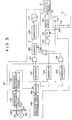
- This control system 23 is shown in block diagram form in Fig. 5, along with the electromagnetic brake 13 which is schematically shown by a block.
- -Also shown as a block is a driver circuit 120 incorporated in said control system 23, similar to the driver circuit of the first and second preferred control systems 23 shown in Figs. 3 and 4, which incorporates an electrical power supply starting circuit and an electrical power cutting off circuit, neither of which are particularly shown in the figures.
- this electrical power supply starting circuit functions so as to commence the supply of actuating electrical energy to the electromagnetic brake 13, and the electrical power cutting off circuit within the driver circuit 120 functions so as to cut off the supply of actuating electrical energy to the electromagnetic brake 13, according to the selective supply to said driver circuit 120 of a 1 signal or of a 0 signal, this so called engage or disengage signal as will be seen later being provided from the output of a second flip-flop circuit 231.
- the gist of this shown third preferred control system 23 relates to the method of engaging of the electromagnetic brake 13, in order to avoid vehicle skidding, as will become apparent hereinafter. Accordingly, although for the sake of simplicity of explanation in this third preferred control system this engage or disengage signal generating part of said control system 23 operates only according to the signals from one sensor switch, which is an accelerator pedal sensor switch 111, which is similar to the accelerator pedal sensor switch 111 of the first and the second preferred control systems 23 shown and described above, and does not include any parking range sensor switch such as the parking range sensor switch 112 of the first and the second preferred control systems 23 or any parking brake sensor switch such as the parking brake sensor switch 123 of the second preferred control system 23, it will be understood by one skilled in the art, based upon the disclosure in this specification, that the concepts shown with respect to said first and second preferred control systems 23 for releasing the electromagnetic brake 13 can also be applied to this third preferred control system 23.
- This accelerator pedal sensor switch 111 is open when the accelerator pedal (not shown) which controls the internal combustion engine of the vehicle is not depressed at all, and is closed when said accelerator pedal is depressed by even a small amount from the non depressed condition.
- One terminal of the accelerator pedal sensor switch 111 is connected to ground, and the other terminal 111 a of the accelerator pedal sensor switch 111 is connected via a resistive element 114 to a power source such as the battery of the vehicle.
- the voltage signal present at said other terminal 111a of said accelerator pedal sensor switch 111 is a 1 or 0 signal (taking ground potential as a 0 signal) indicating respectively whether said accelerator pedal sensor switch 111 is open or closed, i.e.
- This signal present at said other terminal 111a of said accelerator pedal sensor switch 111 is fed into said control system 23 through its input terminal 229.
- the control system 23 also comprises a vehicle wheel revolution speed sensor 212 which is of a per se well known kind, comprising a rotor 213 which is rotated at a speed proportional to the road speed of one of the wheels of the vehicle, which in the shown third preferred control system 23 is a preferred wheel as far as the anti skid and brake engaging action is concerned.
- This rotor 213 has four lobes, and these lobes repeatedly in turn push against the switched member of a reed switch 214, and release said switched member.
- One terminal of the reed switch 214 is connected to ground, and the other terminal 214a of the reed switch 214 is connected via a resistive element 200 to a power source such as the battery of the vehicle.
- the voltage signal which will be referred to as signal "a” in the following, present at said other terminal 214a of the reed switch 214 is a 1 or 0 pulsed signal (taking ground potential as a 0 signal) indicating by its pulse frequency the rotational speed of said wheel of the vehicle, with the reed switch 214 opening and closing four times for each revolution of the rotor 213.
- this pulse voltage signal "a" present at said other terminal 214a of the reed switch 214 increases in frequency, i.e. decreases in wavelength, according to increasing rotational speed of said wheel of the vehicle.
- this pulse signal "a” present at said other terminal 214a of the reed switch 214 which is fed into said control system 23 through its input terminal 211, is fed to the input of a first monostable multivibrator circuit 215, which belongs to an electrical pulse generation system of the vehicle wheel revolution speed sensing system and produces an output pulse on a rise or upward slope of said pulse signal "a", as can be exemplarily seen in Fig. 6-b, in which graph time is the abscissa and voltage is the ordinate.
- This output signal of the monostable multivibrator circuit 215 will be referred to as signal "b" in the following.
- Signal "b” is fed to one input terminal of an AND gate 217 and to one input terminal of another AND gate 218, as will be explained later, and is also fed to the input of a second monostable multivibrator circuit 216, which produces an output pulse on a fall or downward slope of said pulse signal "b" output from the first monostable multivibrator circuit 215, as can be exemplarily seen in Fig. 6-c, in which graph again time is the abscissa and voltage is the ordinate.
- This output signal of the second monostable multivibrator circuit 216 will be referred to as signal “c” in the following, and it will be understood by one skilled in the art that each pulse of the output signal “c” of the second monostable multivibrator circuit 216 starts just after the end of a corresponding pulse of the output signal "b" of the first monostable multivibrator circuit 215.
- This signal “c” output from the second monostable multivibrator circuit 216 is fed to the RESET terminal of a first counter 219, whose counting input is supplied with the clock pulse signal, which will be referred to as signal “d” in the following, output from a clock pulse signal generating circuit 220.
- This clock pulse signal “d” can be exemplarily seen in Fig. 6-d, in which graph again time is the abscissa and voltage is the ordinate.
- the first counter 219 counts the number of clock pulses in the clock pulse signal "d" which it receives from the clock pulse signal generating circuit 220, from the last pulse of the output signal "c" of the second monostable multivibrator circuit 216 which RESET said first counter 219, and when the next pulse of said output signal "c" of the second monostable multivibrator circuit 216 is received by said first counter 219, said first counter 219 outputs the counter result at its output terminal and resets itself to zero for the next count. Accordingly, at the output terminal of said first counter 219 there appears, at every one of the pulses of the output signal "c" of the second monostable multivibrator circuit 216, i.e.
- a counted number indicative of the rotational speed of said preferred wheel of the vehicle is inversely proportional to said rotational speed of said preferred wheel: in other words, the higher is the rotational speed of said wheel, the lower is said counted number, and vice versa, because this counted number is the number of pulses of the clock pulse signal "d" generated by the clock pulse signal generating circuit 220 which are produced during the time period that the rotor 213 turns through a quarter of a turn, in this third preferred control system 23.
- This counted number is fed to one of the inputs of each of three comparators: a first comparator 221, a second comparator 222, and a third comparator 223.
- the first comparator 221 compares the value of the counted number which is thus input to said first comparator 221 with a standard value which represents a first predetermined road speed which exemplarily in the following will be taken to be 15 kilometers per hour; and, if the value of said counted number represents a vehicle wheel revolution speed indicating a vehicle road speed of less than said first predetermined road speed, said first comparator 221 outputs a 1 signal at its output terminal, but otherwise outputs a 0 signal. This output signal of the first comparator 221 is fed to the other input terminal of the aforementioned AND gate 217.
- the second comparator 222 compares the value of the counted number which is also thus input to said second comparator 222 with a standard value which represents a second predetermined road speed which exemplarily in the following will be taken to be 2 kilometers per hour; and, if the value of said counted number represents a vehicle wheel revolution speed indicating a vehicle road speed of less than said second predetermined road speed, said second comparator 222 outputs a 1 signal at its output terminal, but otherwise outputs a 0 signal. This output signal of the second comparator 222 is fed to an input terminal of an AND gate 224.
- the third comparator 223 compares the value of the counted number which is also thus input to said third comparator 223 with a standard value which represents a third predetermined road speed which exemplarily in the following will be taken to be 16 kilometers per hour; and, if the value of said counted number represents a vehicle wheel revolution speed indicating a vehicle road speed of greater than said third predetermined road speed, said third comparator 223 outputs a 1 signal at its output terminal but otherwise outputs a 0 signal. This output signal of the third comparator 223 is fed to the other input terminal of the aforementioned AND gate 218.
- a 1 signal output from the first comparator 221 indicates a rotational speed of said preferred wheel corresponding to a vehicle road speed of less than said first predetermined road speed value of 15 kilometers per hour;
- a 1 signal output from the second comparator 222 indicates a rotational speed of said preferred wheel corresponding to a vehicle road speed of less than said second predetermined road speed value of 2 kilometers per hour;
- a 1 signal output from the third comparator 223 indicates a rotational speed of said preferred wheel corresponding to a vehicle road speed of less than said third predetermined road speed value of 16 kilometers per hour.
- the AND gate 217 thus receives at its lower input terminal in Fig. 5 a steady 1 or 0 signal indicating respectively whether or not the current rotational speed of said preferred wheel corresponds to a vehicle road speed of less than said first predetermined road speed value of 15 kilometers per hour or greater than said first predetermined road speed value, and receives at its upper input terminal in Fig. 5 the pulses of the pulse signal "b" output from the first monostable multivibrator circuit 215, if of course said preferred wheel is rotating at all; if on the other hand said preferred wheel is not rotating, then said AND gate 217 of course receives no pulses at all at its upper terminal in Fig. 5.
- the output signal of said AND gate 217 is a steady 0 signal, if either the current rotational speed of said preferred wheel corresponds to a vehicle road speed of greater than said first predetermined road speed value of 15 kilometers per hour, or said preferred wheel is not rotating at all; but otherwise, if said preferred wheel is rotating at least somewhat, but at a rotational speed which corresponds to a vehicle road speed of less than said first predetermined road speed value of 15 kilometers per hour, the output of said AND gate 217 is a stream of pulses which occur at the same times as the pulses of the pulse signal "b" output from the first monostable multivibrator circuit 215.
- the AND gate 218 thus receives at its lower input terminal in Fig. 5 a steady 1 or 0 signal indicating respectively whether or not the current rotational speed of said preferred wheel corresponds to a vehicle road speed of greater than said third predetermined road speed value of 16 kilometers per hour or less than said third predetermined road speed value, and receives at its upper input terminal in Fig. 5 the pulses of the pulse signal "b" output from the first monostable multivibrator circuit 215, if of course said preferred wheel is rotating at all; if on the other hand said preferred wheel is not rotating, then said AND gate 218 of course receives no pulses at all at its upper terminal in Fig. 5.
- the output signal of said AND gate 218 is a steady 0 signal, if either the current rotational speed of said preferred wheel corresponds to a vehicle road speed of less than said third predetermined road speed value of 16 kilometers per hour, or said preferred wheel is not rotating at all; but otherwise, if said preferred wheel is rotating at a rotational speed which corresponds to a vehicle road speed of greater than said third predetermined road speed value of 16 kilometers per hour, the output of said AND gate 218 is a stream of pulses which occur at the same times as the pulses of the pulse signal "b" output from the first monostable multivibrator circuit 215.
- the second counter 225 counts the pulses (if any) of the output signal of said AND gate 217 that have occurred since said second counter 225 was last RESET as will be explained later, and outputs its counted result to the fourth comparator 226.
- This fourth comparator 226 compares this counted result with a standard predetermined count value, which may exemplarily be taken as 3; and, if said number of pulses of the output signal of said AND gate 217 that have occurred since said second counter 225 was last RESET is greater than or equal to said standard predetermined count value of exemplarily 3, said fourth comparator outputs a 1 signal, while, if said number of pulses of the output signal of said AND gate 217 that have occurred since said second counter 225 was last RESET is less than said standard predetermined count value of exemplarily 3, said fourth comparator outputs a 0 signal.
- a 1 signal output from the fourth comparator 226 indicates that since the last RESET of the counter 225 the preferred wheel has rotated at a rotational speed indicative of a vehicle road speed of less than said first predetermined road speed value of 15 kilometers per hour for a certain predetermined road distance, which in fact corresponds to the distance the vehicle moves during three quarters of a turn of the rotor 213 in this third preferred control system 23, assuming that said preferred wheel does not slip on the road surface.
- the output signal of the fourth comparator 226 is supplied to the SET terminal of a first flip-flop circuit 227.
- this first flipflop circuit 227 receives a 1 signal at its said SET terminal, it outputs a 1 signal at its output terminal until it next receives a 1 signal at its RESET terminal, after which said first flipflop circuit 227 outputs a 0 signal at its output terminal until it next receives a 1 signal at its SET terminal.
- the RESET terminal of this first flipflop circuit 227 is supplied with the output signal of an OR gate 228, which is also supplied to the RESET terminal of the second counter 225.
- the OR gate 228 is supplied at one of its input terminals with the output signal of the aforesaid AND gate 218, which as explained above is a steady 0 signal, if either the current rotational speed of said preferred wheel corresponds to a vehicle road speed of less than said third predetermined road speed value of 16 kilometers per hour, or said preferred wheel is not rotating at all; but otherwise, if said preferred wheel is rotating at a rotational speed which corresponds to a vehicle road speed of greater than said third predetermined road speed value of 16 kilometers per hour, is a stream of pulses which occur at the same times as the pulses of the pulse signal "b" output from the first monostable multivibrator circuit 215.
- the OR gate 228 is supplied at its other input terminal with the aforesaid voltage signal present at said other terminal 111 a of said accelerator pedal sensor switch 111, which as previously stated is a 1 or 0 signal indicating respectively whether said accelerator pedal sensor switch 111 is open or closed, i.e. respectively whether the accelerator pedal which controls the internal combustion engine of the vehicle is not depressed at all or is depressed by even a small amount from the non depressed condition, said signal present at said other terminal 111 a of said accelerator pedal sensor switch 111 being fed into said control system 23 through its input terminal 229.
- said second counter 225 and said first flipflop circuit 227 are repeatedly RESET, but otherwise no resetting signal is inputted to. their RESET terminals.
- the output signal of the first flipflop circuit 227 is supplied to one of the input terminals of an AND gate 224, the other of whose input terminals is supplied with the output signal from the second comparator 222, which as previously explained is a 1 signal if and only if said preferred wheel is rotating at a rotational speed corresponding to a vehicle road speed of less than said second predetermined road speed value of 2 kilometers per hour.
- the output of this AND gate 224 is supplied to the SET terminal of the previously mentioned second flipflop circuit 231, the output signal of which is, as stated before, supplied to the electrical power supply starting circuit within the driver circuit 120, which functions so as to commence the supply of actuating electrical energy to the electromagnetic brake 13, and so as to cut off the supply of actuating electrical energy to the electromagnetic brake 13, according to the value of this so called engage or disengage signal provided from the output of said second flipflop circuit 231.
- the RESET terminal of the second flipflop 231 is supplied with the aforesaid voltage signal present at said other terminal 111 a of said accelerator pedal sensor switch 111, which as previously stated is a 1 or 0 signal indicating respectively whether said accelerator pedal sensor switch 111 is open or closed, i.e. respectively whether the accelerator pedal which controls the internal combustion engine of the vehicle is not depressed at all or is depressed by even a small amount from the non depressed condition, via the input terminal 229 of the control system 23.
- this third prefered control system 23 if a certain vehicle road distance (corresponding to three quarters of a turn of the rotor 213) has been traversed without the vehicle road speed becoming over the first predetermined value of exemplarily 15 kilometers per hour or the revolution speed of the preferred wheel becoming zero since the last time that either the vehicle road speed was greater than the third predetermined road speed value of exemplarily 16 kilometers per hour or the accelerator pedal was stepped on by even a little it, then it is taken that the preferred wheel is not skidding, and that the vehicle is coasting or is being braked to a halt.
- this second flipflop circuit 231 When this second flipflop circuit 231 receives this 1 signal at its said SET terminal, it outputs a 1 signal at its output terminal until it next receives a 1 signal at its RESET terminal, after which second flipflop circuit 231 outputs a 0 signal at its output terminal until it next receives a 1 signal at its SET terminal.
- a 1 signal commences to be output to the driver circuit 120, which then functions so as to commence the supply of actuating electrical energy to the electromagnetic brake 13, and so as therefore, as explained above, to provide braking action locking on action for the braking system of the vehicle, in order to prevent creeping thereof.
- the vehicle, or at least the preferred wheel thereof skids at a vehicle road speed of over the first predetermined road speed of exemplarily 15 kilometers per hour, then because the second counter 225 does not count as many as three (in this third preferred embodiment) of the pulses of the pulse signal "b" from the time that the rotational speed of said preferred wheel becomes less than said first predetermined speed of exemplarily 15 kilometers per hour, because during skidding of the preferred wheel it stops rotating completely, and hence the pulse signal "b" ceases to be produced at all, as explained above, therefore the first flipflop circuit 227 is not subjected to any SET action by the output signal from the fourth comparator 226, and hence the second flipflop circuit 231 is not subjected to any SET action by the output signal from the AND gate 224, and hence no 1 signal is output to the driver circuit 120, which accordingly does not commence supply of actuating electrical energy to the electromagnetic brake 13. Accordingly, no braking action locking on action is provided for the braking system of the vehicle, and hence no danger exists
- the second counter 225 has counted as many as three (in this third preferred control system 23) of the pulses of the pulse signal "b" from the time that the rotational speed of said preferred wheel became less than said first predetermined speed of exemplarily 15 kilometers per hour, and thus the first flipflop circuit 227 is SET, and if then subsequently the road speed of the vehicle becomes greater than the third predetermined speed of exemplarily 16 kilometers per hour, or alternatively the vehicle is accelerated by even slight depression of the accelerator pedal thereof, then because the output of the AND gate 218 becomes a 1 signal, or alternatively because a 1 signal is input to the input terminal 229 of the control system 23 from the said other terminal 111 a of the accelerator pedal sensor switch 111, therefore the output of the OR gate 228 also becomes a 1 signal, and hence the first flipflop circuit 227 is
- this third preferred control system 23 it is tested as to whether the preferred wheel is skidding or not, and if it is skidding then positively the braking force retaining action of the anti creep braking system is not applied. Thus, it is positively prevented that the vehicle should become locked into a skid, which is advantageous from the point of view of safety, and increases the drivability and the controllability of the vehicle.
- the shown third preferred control system 23 considers the case of sensing the revolution speed of just one wheel of the vehicle, i.e. of the so called preferred wheel thereof, in fact it would not be difficult to modify and amplify the shown control system to consider the revolution speeds of all four of the wheels of a four wheeled vehicle.
- the control system 23 might be provided in quadruplicate, and in this case the output signals from the four flipflop circuits corresponding to the shown second flipflop circuit 231 might be fed to a four way AND gate, the output of which might be fed to the driver circuit 120.
- the anti creep braking system braking action retaining action would only be provided. if it had been detected positively that no one of the four vehicle wheels was skidding.
- One skilled in the art can easily fill in the details of this possible variation, based upon the disclosure contained herein.
- the fourth preferred control system is the fourth preferred control system
- Fig. 7 there is shown the fourth preferred control system 23, in a fashion similar to Figs. 3, 4, and 5.
- parts, which correspond to parts shown respectively in Figs. 3, 4, and 5, and which have the same functions, are designated by the same reference numerals and symbols as in those figures.
- control system 23 which selectively supplies actuating electrical energy to the electromagnetic coil 14 of the electromagnetic brake 13 will be explained.
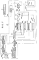
- This control system 23 is shown in block diagram form in Fig. 7, along with the electromagnetic brake 13 which is schematically shown by a block.
- a driver circuit 120 incorporated in said control system 23, similar to the driver circuit of the first, second, and third preferred control systems 23 shown in Figs. 3, 4, and 5, which incorporates an electrical power supply starting circuit and an electrical power cutting off circuit, neither of which are particularly shown in the figures.
- this electrical power supply starting circuit functions so as to commence the supply of actuating electrical energy to the electromagnetic brake 13, and the electrical power cutting off circuit within the driver circuit 120 functions so as to cut off the supply of actuating electrical energy to the electromagnetic brake 13, according to the selective supply to said driver circuit 120 of a 1 signal or of a 0 signal, this so called engage or disengage signal as will be seen later being provided from the output of a second flipflop circuit 231.
- the gist of this shown fourth preferred control system 23 relates to the method of engaging of the electromagnetic brake 13, in order to avoid vehicle skidding, as will become apparent hereinafter, similarly to the gist of the third preferred control system 23 shown in Fig: 5.
- the details of this fourth preferred control system 23 differ in some important aspects from the details of the third preferred control system 23.
- this engage or disengage signal generating part of said control system 23 operates only according to the signals from one sensor switch, which is an accelerator pedal sensor switch 111, which is similar to the accelerator pedal sensor switch 111 of the first and the second preferred control systems 23 shown and described above, and the accelerator pedal sensor switch 111 of the third preferred control system 23 and although this fourth preferred control system 23 does not include any parking range sensor switch such as the parking range sensor switch 112 of the first and the second preferred control systems 23 or any parking brake sensor switch such as the parking brake sensor switch 123 of the second preferred control system 23 it will be understood by one skilled in the art, based upon the disclosure in this specification, that the concepts shown with respect to said first and second preferred control systems 23 for releasing the electromagnetic brake 13 can also be applied to this fourth preferred control system 23.
- This accelerator pedal sensor switch 111 is open when the accelerator pedal (not shown) which controls the internal combustion engine of the vehicle is not depressed at all, and is closed when said accelerator pedal is depressed by even a small amount from the non depressed condition.
- One terminal of the accelerator pedal sensor switch 111 is connected to ground, and the other ter- mina! 111 a of the accelerator pedal sensor switch 111 is connected via a resistive element 114 to a power source such as the battery of the vehicle.
- the voltage signal present at said other terminal 111 a of said accelerator pedal sensor switch 111 is a 1 or 0 signal (taking ground potential as a 0 signal) indicating respectively whether said accelerator pedal sensor switch 111 is open or closed, i.e.
- This signal present at said other terminal 111 a of said accelerator pedal sensor switch 111 is fed into said control system 23 through its input terminal 229.
- the control system 23 also comprises a vehicle wheel revolution speed sensor 212 which is of a per se well known kind, comprising a rotor 213 which is rotated at a speed proportional to the road speed of one of the wheels of the vehicle, which in the shown fourth preferred control system 23 again is a preferred wheel as far as the anti-skid and brake engaging action is concerned.
- This rotor 213 has four lobes, and these lobes repeatedly in turn push against the switched member of a reed switch 214, and release said switched member.
- One terminal of the reed switch 214 is connected to ground, and the other terminal 214a of the reed switch 214 is connected via a resistive element 200 to a power source such as the battery of the vehicle.
- the voltage signal which will be referred to as signal "a” in the following, present at said other terminal 214a of the reed switch 214 is a 1 or 0 pulses signal (taking ground potential as a 0 signal) indicating by its pulse frequency the rotational speed of said preferred wheel of the vehicle, with the reed switch 214 opening and closing four times for each revolution of the rotor 213.
- this pulse voltage signal "a" present at said other terminal 214a of the reed switch 214 increases in frequency, i.e. decreases in wavelength, according to increasing rotational speed of said preferred wheel of the vehicle.
- terminal 211 is fed to the input of a first monostable multivibrator circuit 215, which produces an output pulse on a rise or upward slope of said pulse signal "a”, as can be exemplarily seen in Fig. 6-b.
- This output signal of the monostable multivibrator circuit 215 will be referred to as signal "b" in the following.
- Signal "b” is fed to one input terminal of an AND gate 218 and to the SHIFT terminal of a shift register 234, as will be explained later, and is also fed to the input of a second monostable multivibrator circuit 216, which produces an output pulse on a fall or downward slope of said pulse signal "b" output from the first monostable multivibrator circuit 215, as can be exemplarily seen in Fig. 6-c.
- This output signal of the second monostable multivibrator circuit 216 will be referred to as signal “c” in the following, and it will be understood by one skilled in the art that each pulse of the output signal “c” of the second monostable multivibrator circuit 216 starts just after the end of a corresponding pulse of the output signal "b" of the first monostable multivibrator circuit 215.
- This signal “c” output from the second monostable multivibrator circuit 216 is fed to the RESET terminal of a counter 219, whose counting input is supplied with the clock pulse signal, which will be referred to as signal “d” in the following, output from a clock pulse signal generating circuit 220.
- This clock pulse signal “d” can be exemplarily seen in Fig. 6-d.
- the counter 219 counts the number of clock pulses in the clock pulse signal "d" which it receives from the clock pulse signal generating circuit 220, from the last pulse of the output signal "c" of the second monostable multivibrator circuit 216 which RESET said counter 219, and when the next pulse of said output signal "c" of the second monostable multivibrator circuit 216 is received by said counter 219, said counter 219 outputs the counted result at its output terminal and resets itself to zero for the next count. Accordingly, at the output terminal of said counter 219 there appears, at every one of the pulses of the output signal "c" of the second monostable multivibrator circuit 216, i.e.
- a counted number indicative of the rotational speed of said preferred wheel of the vehicle is inversely proportional to said rotational speed of said preferred wheel: in other words, the higher is the rotational speed of said wheel, the lower is said counted number, and vice versa, because this counted number is the number of pulses of the clock pulse signal "d” generated by the clock pulse signal generating circuit 220 which are produced during the time period that the rotor 213 turns through a quarter of a turn, in this fourth preferred control system 23.
- This counted number is fed to the input terminal of the above mentioned shift register 234, and to one of the inputs of each of two comparators: a first comparator 222 and a second comparator 223.
- the shift register 234 receives the value of this counted number of pulses from the counter 219 at its input terminal, and, every time that said shift register 234 receives a SHIFT signal, i.e. a 1 pulse, at its SHIFT terminal from the first monostable multivibrator circuit 215, in other words at each one of the pulses of the output signal "b" of the first monostable multivibrator circuit 216 (the presence of which indicates that the preferred wheel is turning and is not locked, as in the previously described third preferred control system 23), said shift register 234 shifts the value formerly stored in its Y storage register to its Z storage register (the value in which is overwritten), shifts the value formerly stored in its X storage register to its Y storage register, and stores the value currently present at its input terminal in its X storage register.
- a SHIFT signal i.e. a 1 pulse
- this shift register 234 receives at its RESET terminal the signal present at said other terminal 111 a of said accelerator pedal sensor switch 111, which as mentioned above is a 1 or 0 signal indicating respectively whether said accelerator pedal sensor switch 111 is open or closed, i.e. respectively whether the accelerator pedal which controls the internal combustion engine of the vehicle is not depressed at all, or is depressed by even a small amount from the non depressed condition, and which is fed into the control system 23 through its input terminal 229.
- the shift register 234 is RESET whenever the accelerator pedal of the vehicle is depressed by even a small amount.
- the value stored in the X storage register of the shift register 234 is fed to one of the inputs of a fifth comparator 237; the value stored in the Y storage register of the shift register 234 is fed to one of the inputs of a fourth comparator 236; and the value stored in the Z storage register of the shift register 234 is fed to one of the inputs of a third comparator 235. Further, the value stored in the Y storage register of the shift register 234 is also fed to the other input of the fifth comparator 237 as a reference value, and the value stored in the Z storage register of the shift register 234 is also fed to the other input of the fourth comparator 236 as a reference value.
- the third comparator receives a standard reference value signal indicative of a first predetermined road speed which exemplarily in the following will be taken to be 15 kilometers per hour.
- the first comparator 222 compares the value of the counted number which is thus input to said first comparator 222 with a standard value which represents a second predetermined road speed which exemplarily in the following will be taken to be 2 kilometers per hour; and, if the value of said counted number represents a vehicle wheel revolution speed indicating a vehicle road speed of less than said second predetermined road speed, said first comparator 222 outputs a 1 signal at its output terminal, but otherwise outputs a 0 signal. This output signal of the first comparator 222 is fed to an input terminal of an AND gate 224.
- the second comparator 223 compares the value of the counted number which is also thus input to said second comparator 223 with a standard value which represents a third predetermined road speed which exemplarily in the following will be taken to be 16 kilometers per hour; and, if the value of said counted number represents a vehicle wheel revolution speed indicating a vehicle road speed of greater than said third predetermined road speed, said second comparator 223 outputs a 1 signal at its output terminal, but otherwise outputs a 0 signal. This output signal of the second comparator 223 is fed to the other input terminal of the aforementioned AND gate 218.
- the third comparator 235 compares the value stored in the Z storage register of the shift register 234 with said standard value which represents said first predetermined road speed which exemplarily has been taken to be 15 kilometers per hour; and, if the value of said counted number represents a vehicle wheel revolution speed indicating a vehicle road speed of less than said first predetermined road speed, said third comparator 235 outputs a 1 signal at its output terminal, but otherwise outputs a 0 signal. This output signal of the third comparator 235 is fed to a first input terminal of a three way AND gate 217.
- the fourth comparator 236 compares the value stored in the Y storage register of the shift register 234 with said value stored in the Z storage register of the shift register 234; and, if said value stored in the Y storage register of the shift register 234 represents a vehicle wheel revolution speed indicating a vehicle road speed of less than the road speed indicated by the vehicle wheel revolution speed represented by said value stored in the Z storage register of the shift register 234, said fourth comparator 236 outputs a 1 signal at its output terminal, but otherwise outputs a 0 signal. This output signal of the fourth comparator 236 is fed to the second input terminal of the three way AND gate 217.
- the fifth comparator 237 compares the value stored in the X storage register of the shift register 234 with said value stored in the Y storage register of the shift register 234; and, if said value stored in the X storage register of the shift register 234 represents a vehicle wheel revolution speed indicating a vehicle road speed of less than the road speed indicted by the vehicle wheel revolution speed represented by said value stored in the Y storage register of the shift register 234, said fifth comparator 237 outputs a 1 signal at its output terminal, but otherwise outputs a 0 .signal. This output signal of the first comparator 237 is fed to the third input terminal of the three way AND gate 217.
- a 1 signal output from the first comparator 222 indicates a rotational speed of said preferred wheel corresponding to a vehicle road speed of less than said second predetermined road speed value of 2 kilometers per hour;
- a 1 signal output from the second comparator 223 indicates a rotational speed of said preferred wheel corresponding to a vehicle road speed of greater than said third predetermined road speed value of 16 kilometers per hour;
- a 1 signal output from the third comparator 235 indicates a rotational speed of said preferred wheel on the last but second pulse.
- a 1 signal output from the fourth comparator 236 indicates a rotational speed of said preferred wheel on the last but one pulse of the pulse signal "b” output from the first monostable vibrator circuit 215 corresponding to a vehicle road speed of less than the vehicle road speed to which the rotational speed of said preferred wheel on the last but second pulse of the aforesaid pulse signal "b" output from the first monostable vibrator circuit 215 corresponded; and, finally, a 1 signal which is output from the fifth comparator 237 is indicative of a rotational speed of said preferred wheel on the last pulse of the pulse signal "b” output from the first monostable vibrator circuit 215 corresponding to a vehicle road speed of less than the vehicle road speed to which the rotational speed of said preferred wheel on the last but one pulse of the pulse signal "b” output from the first monostable vibrator circuit 215 corresponde
- the AND gate 217 thus receives at its upper input terminal in Fig. 7 a 1 or 0 signal indicating respectively whether or not the rotational speed of said preferred wheel on the last but second pulse of the pulse signal "b" output from the first monostable vibrator circuit 215 corresponds to a vehicle road speed of less than said first predetermined road speed value of 15 kilometers per hour or greater than said first predetermined road speed value; receives at its middle input terminal in Fig.
- the output signal of said AND gate 217 is a steady 0 signal, if either said preferred wheel is not rotating at all, or the values of the rotational speed of said preferred wheel at the times of the last, the last but one, and the last but second pulses of the pulse signal "b" output from the first monostable vibrator circuit 215 do not correspond to a sequence of vehicle road speeds steadily decreasing from said first predetermined road speed value of 15 kilometers per hour; but otherwise, if said preferred wheel is rotating at least somewhat, and the values of the rotational speed of said preferred wheel at the times of the last, the last but one, and the last but second pulses of the pulse signal "b" output from the first monostable vibrator circuit 215 correspond to a sequence of vehicle road speeds steadily decreasing from said first predetermined road speed value of 15 kilometers per hour, then the output of said AND gate 217 is a stream of pulses which occur at the same times as the pulses of the pulse signal "b" output from the first monostable multivibrator circuit 215.
- a 1 signal output from the three way AND gate 217 indicates that since the last RESETting of the shift register 234 the preferred wheel has rotated at a steadily diminishing rotational speed, but not a zero rotational speed, which is indicative of a steadily diminishing vehicle road speed of less than said first predetermined road speed value of 15 kilometers per hour for a certain predetermined road distance which in fact corresponds to the distance required for three pulses of the pulse signal "b" output from the first monostable multivibrator circuit 215 to occur, in this fourth preferred control system 23.
- This output signal from the AND gate 217 is directly fed to the SET terminal of a first flipflop circuit 227.
- the AND gate 218 receives at its upper input terminal in Fig. 7 a 1 or 0 signal indicating respectively whether or not the current rotational speed of said preferred wheel corresponds to a vehicle road speed of greater than said third predetermined road speed value of exemplarily 16 kilometers per hour or less than said third predetermined road speed value, and receives at its lower input terminal in Fig. 7 the pulses of the pulse signal "b" output from the first monostable multivibrator circuit 215, if of course said preferred wheel is rotating at all; if on the other hand said preferred wheel is not rotating, then said AND gate 218 of course receives no pulses at all at its upper terminal in Fig. 7.
- the output signal of said AND gate 218 is a steady 0 signal, if either the current rotational speed of said preferred wheel corresponds to a vehicle road speed of less than said third predetermined road speed value of 16 kilometers per hour, or said preferred wheel is not rotating at all; but otherwise, if said preferred wheel is rotating at a rotational speed which corresponds to a vehicle road speed of greater than said third predetermined road speed value of 16 kilometers per hour, the output of said AND gate 218 is a stream of pulses which occur at the same times as the pulses of the pulse signal "b" output from the first monostable multivibrator circuit 215.
- the first flipflop circuit 227 When the first flipflop circuit 227 receives a 1 signal at its said SET terminal, it outputs a 1 signal at its output terminal until it next receives a 1 signal at its RESET terminal, after which said first flipflop circuit 227 outputs a 0 signal at its output terminal until it next receives a 1 signal at its SET terminal.
- the RESET terminal of this first flipflop circuit 227 is supplied with the output signal of an OR gate 228.
- the OR gate 228 is as mentioned above supplied at one of its input terminals with the output signal of the aforesaid AND gate 218, which as explained above is a steady 0 signal, if either the current rotational speed of said preferred wheel corresponds to a vehicle road speed of less than said third predetermined road speed value of 16 kilometers per hour, or said preferred wheel is not rotating at all; but othewise, if said preferred wheel is rotating at a rotational speed which corresponds to a vehicle road speed of greater than said third predetermined road speed value of 16 kilometers per hour, is a stream of pulses which occur at the same times as the pulses of the pulse signal "b" output from the first monostable multivibrator circuit 215.
- the OR gate 228 is supplied at its other input terminal with the aforesaid voltage signal present at said other terminal 111 a of said accelerator pedal sensor switch 111, which as previously stated is a 0 or 1 signal indicating respectively whether said accelerator pedal sensor switch 111 is closed or open, i.e. respectively whether the accelerator pedal which controls the internal combustion engine of the vehicle is not depressed at all or is depressed by even a small amount from the non depressed condition, said signal present at said other terminal 111 a of said accelerator pedal sensor switch 111 being fed into said control system 23 through its input terminal 229.
- said first flipflop circuit 227 is repeatedly RESET, but otherwise no resetting signal is inputted to its RESET terminal.
- the output signal of the first flipflop circuit 227 is supplied to one of the input terminals of an AND gate 224, the other of whose input terminals is supplied with the output signal from the first comparator 222, which as previously explained is a 1 signal if and only if said preferred wheel is rotating at a rotational speed corresponding to a vehicle road speed of less than said second predetermined road speed value of 2 kilometers per hour.
- the output of this AND gate 224 is supplied to the SET terminal of the previously mentioned second flipflop circuit 231, the output signal of which is, as stated before, supplied to the electrical power supply starting circuit within the driver circuit 120, which functions so as to commence the supply of actuating electrical energy to the electromagnetic brake 13, and so as to cut off the supply of actuating electrical energy to the electromagnetic brake 13, according to the value of this so called engage or disengage signal provided from the output of said second flipflop circuit 231.
- the RESET terminal of the second flipflop 231 is supplied, via the input terminal 229 of the control system 23, with the aforesaid voltage signal present at said other terminal 111 a of said accelerator pedal sensor switch 111, which as previously stated is a 0 or 1 signal indicating respectively whether said accelerator pedal sensor switch 111 is closed or open, i.e. respectively whether the accelerator pedal which controls the internal combustion engine of the vehicle is not depressed at all or is depressed by even a small amount from the non depressed condition.
- this fourth preferred control system 23 if a certain road distance has passed with the vehicle road speed steadily dropping from the first predetermined value of exemplarily 15 kilometers per hour, without the vehicle road speed becoming over the first predetermined value of exemplarily 15 kilometers per hour or the revolution speed of the preferred wheel becoming zero, since the last time that either the vehicle road speed was greater than the third predetermined road speed value of exemplarily*16 kilometers per hour or the accelerator pedal was stepped on by even a little bit, then it is taken that the preferred wheel is not skidding, and that the vehicle is coasting or is being braked to a halt.
- a 1 signal commences to be output to the driver circuit 120, which then functions so as to commence the supply of actuating electrical energy to the electromagnetic brake 13, and so as therefore, as explained above, to provide braking action locking on action for the braking system of the vehicle, in order to prevent creeping thereof.
- this fourth preferred control system 23 it is tested as to whether the preferred wheel is skidding or not, and if it is skidding then positively the braking force retaining action of the anti creep braking system is not applied. Thus, it is positively prevented that the vehicle should become locked into a skid, which is advantageous from the point of view of safety, and increases the drivability and the controllability of the vehicle.
- the shown fourth preferred control system considers the case of sensing the revolution speed of just one wheel of the vehicle, i.e. of the so called preferred wheel thereof, in fact it would not be difficult to modify and amplify the shown control system to consider the revolution speeds of all four of the wheels of a four wheeled vehicle.
- the control system 23 might. be provided in quadruplicate, and in this case the output signals from the four flipflop circuits corresponding to the shown second flipflop circuit 231 might be fed to a four way AND gate, the output of which might be fed to the driver circuit 120.
- the anti creep braking system braking action retaining action would only be provided, if it had been detected positively that no one of the four vehicle wheels was skidding.
- One skilled in the art can again easily fill in details of this possible variation, based upon the disclosure contained herein.
Landscapes
- Engineering & Computer Science (AREA)
- Chemical & Material Sciences (AREA)
- Combustion & Propulsion (AREA)
- Transportation (AREA)
- Mechanical Engineering (AREA)
- Automation & Control Theory (AREA)
- Physics & Mathematics (AREA)
- General Physics & Mathematics (AREA)
- Regulating Braking Force (AREA)
Claims (8)
Applications Claiming Priority (6)
| Application Number | Priority Date | Filing Date | Title |
|---|---|---|---|
| JP7497781U JPS57187262U (fr) | 1981-05-22 | 1981-05-22 | |
| JP56078235A JPS57194143A (en) | 1981-05-22 | 1981-05-22 | Braking force holder for car |
| JP74977/81U | 1981-05-22 | ||
| JP78235/81 | 1981-05-22 | ||
| JP56079732A JPS57194144A (en) | 1981-05-25 | 1981-05-25 | Brake state detector for car |
| JP79732/81 | 1981-05-25 |
Publications (3)
| Publication Number | Publication Date |
|---|---|
| EP0066043A2 EP0066043A2 (fr) | 1982-12-08 |
| EP0066043A3 EP0066043A3 (en) | 1984-06-13 |
| EP0066043B1 true EP0066043B1 (fr) | 1988-06-08 |
Family
ID=27301670
Family Applications (1)
| Application Number | Title | Priority Date | Filing Date |
|---|---|---|---|
| EP82101738A Expired EP0066043B1 (fr) | 1981-05-22 | 1982-03-04 | Système de freinage de véhicule évitant l'avancement, permettant l'application de freinage additionnel |
Country Status (3)
| Country | Link |
|---|---|
| US (1) | US4497395A (fr) |
| EP (1) | EP0066043B1 (fr) |
| DE (1) | DE3278630D1 (fr) |
Families Citing this family (18)
| Publication number | Priority date | Publication date | Assignee | Title |
|---|---|---|---|---|
| FR2618924B1 (fr) * | 1987-07-31 | 1992-01-24 | Peugeot | Dispositif d'assistance pour une commande de correcteurs d'assiette de vehicules automobiles |
| EP0317303A3 (en) * | 1987-11-20 | 1990-07-04 | Lucas Industries Public Limited Company | Rotary electric drive device |
| EP0392732A1 (fr) * | 1989-04-14 | 1990-10-17 | Eaton Corporation | Dispositif de commande de démarrage pour une transmission mécanique automatique |
| US5137127A (en) * | 1991-04-03 | 1992-08-11 | Eaton Corporation | Motor vehicle hill holder system |
| FR2696397B1 (fr) * | 1992-10-07 | 1994-12-02 | Bendix Europ Services Tech | Dispositif de pédale pour véhicule automobile notamment pour système de freinage. |
| JP3414023B2 (ja) * | 1995-01-27 | 2003-06-09 | トヨタ自動車株式会社 | ブレーキ操作装置 |
| US5921354A (en) * | 1996-05-07 | 1999-07-13 | Kelsey-Hayes Company | Self-energizing anti-creep parking and emergency brake mechanism for disc brake assembly |
| US6530450B2 (en) | 2000-08-09 | 2003-03-11 | Deluca Michael | Fault reactive securely stopped vehicle method and apparatus |
| US6286617B1 (en) * | 2000-08-09 | 2001-09-11 | Deluca Michael | Securely stopped vehicle method and apparatus |
| US6543567B2 (en) | 2000-08-09 | 2003-04-08 | Deluca Michael | Fault responsive securely stopped vehicle method and apparatus |
| US9827954B2 (en) * | 2006-08-18 | 2017-11-28 | Dura Operating, Llc | Release mechanism for a parking brake clutch |
| US8205523B2 (en) * | 2007-12-10 | 2012-06-26 | Club Car, Llc | Pedal assembly for vehicles |
| DE102009053021A1 (de) * | 2008-12-04 | 2010-06-10 | Luk Lamellen Und Kupplungsbau Beteiligungs Kg | Kriechvorgang |
| KR101406438B1 (ko) * | 2013-04-16 | 2014-06-13 | 기아자동차주식회사 | 차량용 페달 장치 |
| WO2015019766A1 (fr) * | 2013-08-05 | 2015-02-12 | 日産自動車株式会社 | Dispositif de commande de véhicule et procédé de commande de véhicule |
| US9896071B2 (en) * | 2014-10-30 | 2018-02-20 | Ford Global Technologies, Llc | Automatic brake hold with low speed maneuverability |
| JP6852658B2 (ja) * | 2017-11-24 | 2021-03-31 | 株式会社デンソー | 車両用制御装置 |
| KR102859891B1 (ko) * | 2019-07-09 | 2025-09-16 | 현대자동차주식회사 | 친환경 자동차 및 그를 위한 발진 제어 방법 |
Family Cites Families (10)
| Publication number | Priority date | Publication date | Assignee | Title |
|---|---|---|---|---|
| US2391129A (en) * | 1939-08-15 | 1945-12-18 | Bendix Aviat Corp | Brake mechanism |
| US3498426A (en) * | 1966-10-21 | 1970-03-03 | Akio Nakano | Hydraulic brake operating system for a motor vehicle |
| US3893698A (en) * | 1972-06-12 | 1975-07-08 | Fail Safe Brake Corp | Brake control apparatus |
| US3895698A (en) * | 1972-06-12 | 1975-07-22 | Fail Safe Brake Corp | Brake control apparatus |
| JPS51112028A (en) * | 1975-03-27 | 1976-10-04 | Mizuno Kogeisha:Goushi | Vehicular braking mechanism |
| US4076093A (en) * | 1976-03-31 | 1978-02-28 | Goshi Kaisha Mizuno Kogeisha | Braking control apparatus for a vehicle |
| US4114738A (en) * | 1977-01-17 | 1978-09-19 | Towmotor Corporation | Brake and creeper control system |
| US4136752A (en) * | 1977-05-13 | 1979-01-30 | Towmotor Corporation | Vehicle brake control system |
| US4310064A (en) * | 1979-02-01 | 1982-01-12 | Kazarian Jr Adam | Multi-purpose automobile brake anti-creep device |
| US4289219A (en) * | 1979-11-02 | 1981-09-15 | Fail Safe Industries, Inc. | Control system for vehicle brake valve |
-
1982
- 1982-02-22 US US06/350,571 patent/US4497395A/en not_active Expired - Fee Related
- 1982-03-04 DE DE8282101738T patent/DE3278630D1/de not_active Expired
- 1982-03-04 EP EP82101738A patent/EP0066043B1/fr not_active Expired
Also Published As
| Publication number | Publication date |
|---|---|
| EP0066043A2 (fr) | 1982-12-08 |
| EP0066043A3 (en) | 1984-06-13 |
| US4497395A (en) | 1985-02-05 |
| DE3278630D1 (en) | 1988-07-14 |
Similar Documents
| Publication | Publication Date | Title |
|---|---|---|
| EP0066043B1 (fr) | Système de freinage de véhicule évitant l'avancement, permettant l'application de freinage additionnel | |
| US4561527A (en) | Electric parking brake system for a vehicle | |
| US6905181B2 (en) | Electric parking brake system | |
| JPH07158667A (ja) | クラッチの接触点決定装置及びその方法 | |
| JP4506097B2 (ja) | 車両のパーキング装置 | |
| EP0507466B1 (fr) | Système empêchant le recul dans les pentes pour un véhicule à moteur | |
| CN110461662A (zh) | 车辆用控制装置 | |
| GB2346944A (en) | Motor vehicle with an automatically actuated clutch | |
| US4864504A (en) | Control apparatus for maintaining braking force | |
| JPH10331870A (ja) | 噛合状態の制御のための装置 | |
| EP0067190A1 (fr) | Dispositif pour maintenir un vehicule immobile | |
| JPH07501385A (ja) | クラッチ制御装置 | |
| JPH039330B2 (fr) | ||
| JP2020045053A (ja) | パーキングロック装置 | |
| JP2006327369A (ja) | 車両の制動制御装置 | |
| JP2932753B2 (ja) | 自動定速走行装置 | |
| JP3675491B2 (ja) | 車両制御装置 | |
| JPH1016745A (ja) | 車輪スリップ制御装置 | |
| JPH02102330A (ja) | 絞り弁制御装置 | |
| JPS61249858A (ja) | ブレ−キ制御装置 | |
| KR0136741B1 (ko) | 엔지시동 오프시 브레이크 부스터 진공작동 장치 | |
| JP2007154934A (ja) | デフロック制御装置 | |
| JPH0428833Y2 (fr) | ||
| JPS645617Y2 (fr) | ||
| JP3315058B2 (ja) | 車両用定速走行装置 |
Legal Events
| Date | Code | Title | Description |
|---|---|---|---|
| PUAI | Public reference made under article 153(3) epc to a published international application that has entered the european phase |
Free format text: ORIGINAL CODE: 0009012 |
|
| AK | Designated contracting states |
Designated state(s): DE GB |
|
| PUAL | Search report despatched |
Free format text: ORIGINAL CODE: 0009013 |
|
| RAP1 | Party data changed (applicant data changed or rights of an application transferred) |
Owner name: TOYOTA JIDOSHA KABUSHIKI KAISHA |
|
| AK | Designated contracting states |
Designated state(s): DE GB |
|
| 17P | Request for examination filed |
Effective date: 19840515 |
|
| GRAA | (expected) grant |
Free format text: ORIGINAL CODE: 0009210 |
|
| AK | Designated contracting states |
Kind code of ref document: B1 Designated state(s): DE GB |
|
| REF | Corresponds to: |
Ref document number: 3278630 Country of ref document: DE Date of ref document: 19880714 |
|
| PGFP | Annual fee paid to national office [announced via postgrant information from national office to epo] |
Ref country code: GB Payment date: 19890228 Year of fee payment: 8 |
|
| PLBE | No opposition filed within time limit |
Free format text: ORIGINAL CODE: 0009261 |
|
| STAA | Information on the status of an ep patent application or granted ep patent |
Free format text: STATUS: NO OPPOSITION FILED WITHIN TIME LIMIT |
|
| PGFP | Annual fee paid to national office [announced via postgrant information from national office to epo] |
Ref country code: DE Payment date: 19890428 Year of fee payment: 8 |
|
| 26N | No opposition filed | ||
| PG25 | Lapsed in a contracting state [announced via postgrant information from national office to epo] |
Ref country code: GB Effective date: 19900304 |
|
| GBPC | Gb: european patent ceased through non-payment of renewal fee | ||
| PG25 | Lapsed in a contracting state [announced via postgrant information from national office to epo] |
Ref country code: DE Effective date: 19901201 |