EP0066054A1 - Dispositif de changement de pots pour machines de préparation à la filature, en particulier pour poste d'étirage - Google Patents
Dispositif de changement de pots pour machines de préparation à la filature, en particulier pour poste d'étirage Download PDFInfo
- Publication number
- EP0066054A1 EP0066054A1 EP82102668A EP82102668A EP0066054A1 EP 0066054 A1 EP0066054 A1 EP 0066054A1 EP 82102668 A EP82102668 A EP 82102668A EP 82102668 A EP82102668 A EP 82102668A EP 0066054 A1 EP0066054 A1 EP 0066054A1
- Authority
- EP
- European Patent Office
- Prior art keywords
- rod
- empty
- storage
- filled
- carrier
- Prior art date
- Legal status (The legal status is an assumption and is not a legal conclusion. Google has not performed a legal analysis and makes no representation as to the accuracy of the status listed.)
- Granted
Links
Images


Classifications
-
- D—TEXTILES; PAPER
- D01—NATURAL OR MAN-MADE THREADS OR FIBRES; SPINNING
- D01H—SPINNING OR TWISTING
- D01H9/00—Arrangements for replacing or removing bobbins, cores, receptacles, or completed packages at paying-out or take-up stations ; Combination of spinning-winding machine
- D01H9/005—Arrangements for replacing or removing bobbins, cores, receptacles, or completed packages at paying-out or take-up stations ; Combination of spinning-winding machine for removing empty packages or cans and replacing by completed (full) packages or cans at paying-out stations; also combined with piecing of the roving
- D01H9/008—Arrangements for replacing or removing bobbins, cores, receptacles, or completed packages at paying-out or take-up stations ; Combination of spinning-winding machine for removing empty packages or cans and replacing by completed (full) packages or cans at paying-out stations; also combined with piecing of the roving for cans
Definitions
- the invention relates to a method and a device for changing storage cans on spinning preparation machines, in particular on lines, with a storage can to be filled and an empty storage can provided, and with a first, provided on a first displaceable carrier and pivotable and movable by means of carrier arm for full storage can and a second, provided on a second slidable support by means of support.
- Arm for the empty storage can to move the empty can from a reserve position to a storage position and at the same time move the filled can from the storage position to a delivery position and with a drive for the sliding beams.
- a known feature of such a changing device is that the full and the empty can are moved to the next position in the same cycle.
- Such a changing device is known from German Auslegeschrift No. 1234 597. It uses a so-called rotation changer principle to move filled and empty cans to the next position on an eight-circle-shaped guardrail, i.e. full cans in a collection position and empty cans in a storage position.
- An eight-circle guide rail with swivel arm is provided for the movement of the empty can into the storage position and a similar guide rail arranged above it for the movement of the full can in the dispensing position. Both rails cover the same route. The difference is that the swivel arm is provided for the feed of the empty can at the beginning of one rail, viewed in the feed direction, and that for the full can at the end of the other rail.
- Each rail is driven by its own motor.
- the overdrive from the motor to the rail takes place by means of Rack on the rail and a pinion on the motor.
- the operator must therefore be inclined to operate the drafting system, which not only worsens the accessibility for the operation of the drafting system, but also extends the distance between the operator's position and the drafting system.
- the object of the invention is to remedy these disadvantages.
- the invention as characterized in the claims, solves the problem in such a way that the empty can is shifted when changing in a direction which is essentially at right angles to the direction of displacement of the filled can.
- the object is achieved in that the carriers move forwards and backwards on a straight guide bar are that the guides, viewed in the plan of the device, are at right angles to each other, and that the carriers are connected to one another by a displacement means, and that one of the two carriers is connected to the drive for the forward and backward displacement of both carriers is.
- the empty can can be displaced essentially accelerated in such a way that the initial speed range has a significantly lower average speed than the speed of the filled can.
- the displacement means can be a curved but rigid rod per se, which has the advantage that there is a rigid connection between the two supports, which transmits force in both displacement directions, without the displacement means touching the can to be filled when it is moved backwards.
- the displacement means can be an articulated rod with two or three legs, so that, on the one hand, the process steps are fulfilled when the empty and the filled can are moved forward, and on the other hand, when the two supports are moved backwards by the articulation of the articulated rod, the filling can is not touched becomes.
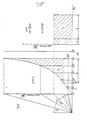
- a can 1 to be filled is in a so-called depositing position, an empty can 2 in a so-called waiting position, and a full can 3 (shown with dash-dotted lines in FIG. 1) in a so-called dispensing position.
- a first pivotable and displaceable arm 4 is arranged in the starting position immediately in front of the can 1 to be filled and a second displaceable arm 5 in the starting position immediately in front of the empty can 2, seen in the direction of forward displacement indicated by an arrow in FIG. 1 .
- the arm 4 and a joint part 6 are components of a later described first support 7 (not shown), while the arm 5 and a joint part 8 are components of a second support 9 described later (not shown).
- the first carrier 7 is on a in the Fig. 1, 2, 4, 5 and 7-14 with the first track 10 indicated by a dash-dotted line, the second carrier 9 arranged on a second track 11 in the aforementioned figures, also indicated with dash-dotted lines, so that it can be moved forwards and backwards.
- the webs 10 and 11 are essentially perpendicular to one another, as viewed in the plan of the device.
- the joint parts 6 and 8 and thus the supports 7 and 9 are connected to one another in an articulated and force-transmitting manner by means of a curved pull and push rod 12.
- this rod 12 is bent such that when the carrier is moved backwards between the end positions of the arms 4 and 5 shown in FIG. 1 (shown in solid or broken lines in FIG. 1), it is the one to be filled Can 1 not touched.
- the rod 12 connects the two carriers 7 and 9, respectively, in such a force-transmitting manner that it is able, when driving one or the other carrier, to move the non-driven carrier together with the full or empty can from the storage position to the dispensing position or from the reserve position to the storage position.
- the arm 4 can be pivoted from the horizontal position shown in FIG. 1 to a vertical position shown in FIG. 2 so that it does not hit the can 1 when it is moved backwards.
- the arm 5 can also be pivoted into a vertical position (not shown in FIGS. 1 and 2). If an empty can 2 is supplied from a direction B after the arm 5 has reached its position shown in solid lines in FIG. 1, it is not necessary to pivot the arm.
- the second carrier 9 displaces as a result of the rigid connection by means of the rod 12 to the first carrier and when the tracks 10 and 11 are perpendicular to one another with a speed profile which is a tangent function for corresponds to an angle d (FIG. 1) between 0 and 90 degrees.
- the leg a corresponds on the one hand to the distance between the The axis of rotation (not shown) of the joint part 6 and the intersection point of the two tracks 10 and 11 of the leg b projected onto the imaginary plan plane previously mentioned, and on the other hand the distance between the axis of rotation of the joint part 8 and the mentioned projected intersection point.
- the cans In order not to obtain a too high final speed of the second carrier or the empty can, the cans must have reached their new position when an angle ⁇ of approx. 75 ° has been reached, i.e. the empty jug the storage position and the filled jug the delivery position.
- the speed of the empty can reaches the value of the full can, since the tangent of 45 ° has the value 1, i.e. the accelerated can has the speed of the constantly driven can at 45 °.
- the initial speed range (for example for ⁇ between 12 0 and 30 °) of the empty jug has a significantly lower average speed than the speed of the full jug.
- the full can has a speed profile corresponding to the tangent function.
- the constructive disposition of the changer would give an initial angle ⁇ ′ which would avoid excessive pressure on the joint 6
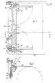
- FIGS. 4 and 5 A variant of the embodiment shown in FIGS. 1 and 2 is shown with FIGS. 4 and 5.
- a resiliently bendable rod 13 is provided as an articulated and force-transmitting connection between the joint parts 6 and 8.
- the path s 2 (FIG. 5) is in the outer end position of the joint part 8, ie in that end position the arm 5 begins to move an empty can 2, limited.
- Such a limitation causes the rod 13 to not be able to extend completely in the aforementioned end position of the joint part 6.
- the first carrier 7 is driven and moves forwards and backwards at a constant speed.
- the joint part 8 is only moved when the joint part 6 has already shifted so far that the rod 13 is in an extended position occupies, ie the angle ⁇ 'has increased to the angle ⁇ ''.
- the size of the two angles depends on the design of the changer.
- the joint part 8 After the angle ⁇ ′′ has been reached, the joint part 8 has a speed profile corresponding to the tangent shown in FIG. 6 during further displacement. The joint parts 6 and 8 are moved, as described earlier, until the angle ⁇ has reached a value of essentially 75 ° .
- the degree of the bend is selected by a controllable damping effect of the damping cylinder 14 (not shown).
- the force stored during this bending of the rod 13 basically causes the second carrier 9 to be moved backwards up to the aforementioned limitation of the path s 2 (not shown), which prevents the carrier from being displaced further. This is given by limiting the piston stroke of the cylinder 14.
- the material of this rod can be spring steel or a suitable plastic, glass or textile fiber composite.
- Fig. 6 indicates with the hatched areas the paths s 1 and s 2 of the filled paths during the changing process Jug 1, or empty jug 2, on.
- FIGS. 7-10 Another variant of the embodiment shown in FIGS. 1 and 2 is shown in FIGS. 7-10.
- an articulated rod 15 is provided therein as an articulated and force-transmitting connection between the articulated parts 6 and 8.
- the joint rod 15 consists of a rod 16 (FIG. 8), as a connection between a joint 17 and the joint part 6, and of a rod 18 as a connection between the joint 17 and the joint part 8.
- rectilinear guide rails 19 and 20 are provided in parallel, which, as subsequently described, serve as a stop for the joint 17.
- the first carrier 7 is driven and moves forwards and backwards at a constant speed.
- the hinge part 8 When changing the can, the hinge part 8 is only moved when the hinge part 6 has already shifted to such an extent that the hinge rod 15 assumes an extended position (indicated in FIG. 7), that is to say that the angle ⁇ 'has increased to the angle ⁇ ".
- the sizes of the two angles depend on the constructive disposition of the changer from.
- the joint part 8 After the angle ⁇ "has been reached, the joint part 8 has a speed profile corresponding to the tangent shown in FIG. 6 during further displacement.
- the joint part 6 is moved, as described earlier, until the angle ⁇ has reached a value of substantially 75 ° (FIG. 8).
- the articulated rod 15 bends (FIG. 9) until the articulation 17 bears against the rail 19 and is passed on until the maximum articulation angle ⁇ has been established.
- This limitation of the articulation angle ⁇ is achieved by a stop (not shown) in the joint 17.
- the second support 9 is also necessarily moved on the second track 11 by means of the joint part 8.
- the joint 17 is lifted and deflected from the rail 19 after the angle ⁇ has been reached, until it abuts against the rail 20 and is passed on until the supports 7 and 9 have reached their starting position again (FIG. 10).
- the kink angle ⁇ opens again up to a certain value / 3 '.
- the size of the value ⁇ and the value ⁇ ' depends on the constructive dispositions of the entire changer device.
- the articulation rod 15 can buckle at the start of the backward displacement either by the articulation rod buckling when the can 1 is touched or by a further stop in the articulation 17 (not shown) which prevents the articulation rod from stretching completely.
- a curved rail 21 (indicated by dashed lines in FIG. 9) can connect the rails 19 and 20 in such a way that the joint 17 moves backwards from the rail 19 is deflected onto the rail 20.
- FIGS. 11-14 A variant of the articulated rod 15 is shown in FIGS. 11-14 with an articulated rod 22.
- FIGS. 13 and 14 details which do not influence the variant have been omitted for a better overview.
- the articulated rod 22 (indicated by dash-dotted lines) is in three parts, i.e. it consists of a rod 23 connected to the joint part 6, a rod 24 connected to the joint part 8 and a central rod 27 connected by means of a joint 25 and 26 to the rod 23 and 24, respectively.
- the supports 7 and 9 connected in an articulated and force-transmitting manner.
- the first carrier 7 is driven and moves forwards and backwards at a constant speed.
- the joint 26 is provided with a stop (not shown) which allows stretching up to a certain angle 1.
- the articulated rod 22 is given a desired bending direction on the one hand and, on the other hand, depending on the structural disposition of the changer device, touching the articulated rod 22 on the can 1, in the position of the cans 1 and 3 shown in FIG. 12, can be avoided.
- the joint 25 also kinks and also slides along the rail 19 until a maximum kink angle ⁇ has been established. Whether the two articulation angles ⁇ and ⁇ are the same or different depends on the constructive disposition of the changer. In contrast, the angle ⁇ (Fig. 11) must not be greater than the angle ⁇ (Fig. 12).
- the rails 19 and 20 can be connected to the curved rail 21 shown in FIG. 9, along which the joints 25 and 26 slide from the rail 19 to the rail 20 change.
- FIGS. 15 to 19 show and describe an embodiment of a changing device in more detail.
- the first carrier 7 comprises a carriage 28 on which two rollers 30 are rotatably provided on an upper part 29 and are guided on an upper rail 31 which represents a first part of the first track 10.
- the rollers 30 serve to horizontally guide the carrier 7.
- two rollers 33 are rotatably provided for vertical guidance and support of the carrier 7 and are supported on a lower rail 34 which represents the second part of the first track 10.
- the rails 31 and 34 are attached to a machine housing 63 of the changer device (not shown).
- Two further rollers 35 which are rotatably arranged on the lower part 32, serve for the further horizontal guidance of the carrier 7.
- the resulting reaction forces P and P '(FIG. 16) caused by the rollers 30 and 35 on the corresponding rails 31 and 34 are directed in opposite directions.
- the joint part 6, on which the rod 16 is arranged in an articulated manner, is also fastened to the lower part 32.
- a pivotable arm 36 is provided on the upper and lower parts 29 and 32. These two arms together make up the first arm 4 mentioned earlier.
- the arms 36 each comprise a support 37, a hinge pin 38 fixedly arranged in the support 37 and an arm blade 39 pivotally mounted thereon.
- the piston rods 40 of a double-acting pneumatic cylinder 41 are pivotally connected to the arm blades 39.
- a stop 42 belonging to the upper part 29 and a stop 43 belonging to the lower part 32 limit the position of the pivoted arm blades 39.
- the vertical position of the arm blades 39 is given by a limited backward stroke of the cylinder pistons 40.
- the second carrier 9 comprises a carriage 44 (FIGS. 18 and 1.9) on which two upper rollers 45 are rotatably arranged on a longitudinal part 46 belonging to the carriage 44, which vertically support the carriage 44 on a rail 47 representing the second track 11. Furthermore, an upper roller 49 and a lower roller 50 are rotatably provided on two supports 48 belonging to the longitudinal part 46 (only one visible in FIG. 18, indicated in FIG. 19 by dashed lines).
- the rollers 49 are supported on a short leg 51 and the rollers 50 on a long leg 52 of the rail 47 and support the chassis 44 in a horizontal position.
- the reaction forces P r and P 1 '(FIG. 18) caused by the rollers 49 and 50 on the legs 51 and 52 are directed in opposite directions.
- the joint part 8 (indicated by dashed lines in FIG. 19) is part of the support 48.
- a pneumatic cylinder 56 is pivotally attached on the cylinder side to a support 57 assigned to the longitudinal part 46 and on the piston side on the arm 5.
- a stop 58 is provided on the longitudinal part 46 to fix the horizontal position of the arm 5.
- a chain drive 59 (FIGS. 15-17), which is driven by a geared motor 60 (only partially shown in FIG. 16), serves as the drive for the undercarriage 28.
- An extended chain pin 61 protrudes into a guide groove 62 provided on the running gear 28 and serves to transmit the force from the chain drive 59 to the running gear 28.
- the mounting of the chain drive and the fastening of the geared motor are not shown.
Landscapes
- Engineering & Computer Science (AREA)
- Mechanical Engineering (AREA)
- Textile Engineering (AREA)
- Spinning Or Twisting Of Yarns (AREA)
- Replacing, Conveying, And Pick-Finding For Filamentary Materials (AREA)
- Warehouses Or Storage Devices (AREA)
- Refuse Receptacles (AREA)
Priority Applications (1)
| Application Number | Priority Date | Filing Date | Title |
|---|---|---|---|
| AT82102668T ATE24465T1 (de) | 1981-05-29 | 1982-03-30 | Vorrichtung zum wechseln von ablagekannen an spinnereivorbereitungsmaschinen, insbesondere an strecken. |
Applications Claiming Priority (2)
| Application Number | Priority Date | Filing Date | Title |
|---|---|---|---|
| CH3513/81 | 1981-05-29 | ||
| CH351381 | 1981-05-29 |
Publications (2)
| Publication Number | Publication Date |
|---|---|
| EP0066054A1 true EP0066054A1 (fr) | 1982-12-08 |
| EP0066054B1 EP0066054B1 (fr) | 1986-12-30 |
Family
ID=4257604
Family Applications (1)
| Application Number | Title | Priority Date | Filing Date |
|---|---|---|---|
| EP82102668A Expired EP0066054B1 (fr) | 1981-05-29 | 1982-03-30 | Dispositif de changement de pots pour machines de préparation à la filature, en particulier pour poste d'étirage |
Country Status (6)
| Country | Link |
|---|---|
| US (1) | US4463480A (fr) |
| EP (1) | EP0066054B1 (fr) |
| JP (1) | JPS57203659A (fr) |
| AT (1) | ATE24465T1 (fr) |
| DE (1) | DE3274836D1 (fr) |
| IN (1) | IN155689B (fr) |
Cited By (2)
| Publication number | Priority date | Publication date | Assignee | Title |
|---|---|---|---|---|
| US4463480A (en) * | 1981-05-29 | 1984-08-07 | Rieter Machine Works, Ltd. | Apparatus and method for changing cans on a spinning preparatory machine |
| DE3618857A1 (de) * | 1986-06-04 | 1987-12-10 | Zinser Textilmaschinen Gmbh | Vorrichtung zum fliegenden wechsel von spinnkannen fuer eine spinnereivorbereitungsmaschine |
Families Citing this family (3)
| Publication number | Priority date | Publication date | Assignee | Title |
|---|---|---|---|---|
| IN161184B (fr) * | 1983-06-21 | 1987-10-17 | Rieter Ag Maschf | |
| DE4212165A1 (de) * | 1992-04-10 | 1993-10-14 | Truetzschler Gmbh & Co Kg | Vorrichtung zum Fördern von Kannen auf der Einlaufseite von Spinnereimaschinen, z. B. Strecken |
| CN112030286B (zh) * | 2020-09-08 | 2021-06-08 | 北自所(北京)科技发展有限公司 | 并条粗纱系统以及用于该并条粗纱系统的条筒输送方法 |
Citations (5)
| Publication number | Priority date | Publication date | Assignee | Title |
|---|---|---|---|---|
| DE1104402B (de) * | 1957-12-13 | 1961-04-06 | Richter Fibrotex K G | Kannenwechselvorrichtung fuer Karden |
| FR1501979A (fr) * | 1966-10-03 | 1967-11-18 | Alsacienne Constr Meca | Dispositif automatique de changement de pot à la sortie d'une machine textile |
| GB1136782A (en) * | 1966-05-23 | 1968-12-18 | Inst Textilmaschinen | A method of and apparatus for changing sliver cans between sliver delivery and feeding sections |
| DE2326950A1 (de) * | 1973-05-26 | 1974-12-19 | Schubert & Salzer Maschinen | Kannenwechselvorrichtung fuer spinnereivorbereitungsmaschinen |
| DE2540981B1 (de) * | 1975-09-13 | 1977-03-17 | Schubert & Salzer Maschinen | Vorrichtung zum Kannenwechsel an Spinnereivorbereitungsmaschinen |
Family Cites Families (5)
| Publication number | Priority date | Publication date | Assignee | Title |
|---|---|---|---|---|
| US3443287A (en) * | 1962-02-09 | 1969-05-13 | Schubert & Salzer Maschinen | Can changing in strand material handling |
| US3808641A (en) * | 1970-05-01 | 1974-05-07 | Schubert & Salzer Maschinen | Can changing devices |
| JPS5127291Y2 (fr) * | 1971-06-16 | 1976-07-10 | ||
| DE2543621C2 (de) * | 1975-09-30 | 1984-11-22 | Zinser Textilmaschinen Gmbh, 7333 Ebersbach | Kannenwechseleinrichtung |
| ATE24465T1 (de) * | 1981-05-29 | 1987-01-15 | Rieter Ag Maschf | Vorrichtung zum wechseln von ablagekannen an spinnereivorbereitungsmaschinen, insbesondere an strecken. |
-
1982
- 1982-03-30 AT AT82102668T patent/ATE24465T1/de not_active IP Right Cessation
- 1982-03-30 DE DE8282102668T patent/DE3274836D1/de not_active Expired
- 1982-03-30 EP EP82102668A patent/EP0066054B1/fr not_active Expired
- 1982-04-12 IN IN401/CAL/82A patent/IN155689B/en unknown
- 1982-05-20 JP JP57084141A patent/JPS57203659A/ja active Granted
- 1982-05-27 US US06/382,687 patent/US4463480A/en not_active Expired - Fee Related
Patent Citations (5)
| Publication number | Priority date | Publication date | Assignee | Title |
|---|---|---|---|---|
| DE1104402B (de) * | 1957-12-13 | 1961-04-06 | Richter Fibrotex K G | Kannenwechselvorrichtung fuer Karden |
| GB1136782A (en) * | 1966-05-23 | 1968-12-18 | Inst Textilmaschinen | A method of and apparatus for changing sliver cans between sliver delivery and feeding sections |
| FR1501979A (fr) * | 1966-10-03 | 1967-11-18 | Alsacienne Constr Meca | Dispositif automatique de changement de pot à la sortie d'une machine textile |
| DE2326950A1 (de) * | 1973-05-26 | 1974-12-19 | Schubert & Salzer Maschinen | Kannenwechselvorrichtung fuer spinnereivorbereitungsmaschinen |
| DE2540981B1 (de) * | 1975-09-13 | 1977-03-17 | Schubert & Salzer Maschinen | Vorrichtung zum Kannenwechsel an Spinnereivorbereitungsmaschinen |
Cited By (2)
| Publication number | Priority date | Publication date | Assignee | Title |
|---|---|---|---|---|
| US4463480A (en) * | 1981-05-29 | 1984-08-07 | Rieter Machine Works, Ltd. | Apparatus and method for changing cans on a spinning preparatory machine |
| DE3618857A1 (de) * | 1986-06-04 | 1987-12-10 | Zinser Textilmaschinen Gmbh | Vorrichtung zum fliegenden wechsel von spinnkannen fuer eine spinnereivorbereitungsmaschine |
Also Published As
| Publication number | Publication date |
|---|---|
| IN155689B (fr) | 1985-02-23 |
| JPH0335227B2 (fr) | 1991-05-27 |
| JPS57203659A (en) | 1982-12-14 |
| DE3274836D1 (en) | 1987-02-05 |
| EP0066054B1 (fr) | 1986-12-30 |
| US4463480A (en) | 1984-08-07 |
| ATE24465T1 (de) | 1987-01-15 |
Similar Documents
| Publication | Publication Date | Title |
|---|---|---|
| DE69121069T2 (de) | Biege-Formeinrichtung von Stangen und Verfahren zum Einbringen von Biegungen der hinteren Enden von Stangen | |
| EP0007556A1 (fr) | Dispositif pour la fabrication de tuyaux transversalement ondulés en matière thermoplastique | |
| DE2439722B2 (de) | Bewegungsgetriebe fuer ein arbeitsorgan | |
| DE1916580A1 (de) | Aufwickelvorrichtung | |
| EP0665722B1 (fr) | Procede et dispositif pour convoyer des pieces planes | |
| DE3928959C1 (fr) | ||
| DE3402514A1 (de) | Vorrichtung zum verpacken von gegenstaenden, insbesondere zigaretten | |
| DE4013656C2 (de) | Vorrichtung zum Spleißen von Bahnen, insbesondere von Papierbahnen für die Herstellung von Wellpappe | |
| DE19601470B4 (de) | Schleppsaugergetriebe, insbesondere Schleppsaugergetriebe für eine Vorrichtung zur Schrägbogenkorrektur | |
| EP0066054A1 (fr) | Dispositif de changement de pots pour machines de préparation à la filature, en particulier pour poste d'étirage | |
| DE2526962A1 (de) | Wickeltraeger | |
| DE1806193A1 (de) | Wickelmaschine | |
| EP0290765B1 (fr) | Dispositif d'avancement, notamment pour corps de boîtes | |
| DE19956796A1 (de) | Biegevorrichtung für das 2- und 3-dimensionale Profilbiegen | |
| DE2414494A1 (de) | Vorrichtung zur steuerung von im hinund hergehenden schlitten von ein- oder mehrstufenpressen angeordneten hilfseinrichtungen | |
| CH672305A5 (fr) | ||
| EP0999161B1 (fr) | Dispositif pour compenser le mouvement d'avance d'une bande de film | |
| DE589328C (de) | Liegende Metallstrangpresse | |
| DE3145519C2 (de) | Einrichtung zum Aufstecken von Tuben, Dosen od. dgl. auf Dorne einer Bearbeitungsmaschine | |
| DD148014A1 (de) | Richtmaschine | |
| DE61451C (de) | Vorrichtung zur Führung von Stoffbahnen an Appreturmaschinen und dergl | |
| DE3818370A1 (de) | Spinnstelle | |
| DE2910874C2 (de) | Einlegegerät | |
| DE3318995A1 (de) | Verpackungsmaschine | |
| DE3037948A1 (de) | Haekelmaschine |
Legal Events
| Date | Code | Title | Description |
|---|---|---|---|
| PUAI | Public reference made under article 153(3) epc to a published international application that has entered the european phase |
Free format text: ORIGINAL CODE: 0009012 |
|
| AK | Designated contracting states |
Designated state(s): AT BE CH DE FR GB IT NL |
|
| 17P | Request for examination filed |
Effective date: 19830114 |
|
| GRAA | (expected) grant |
Free format text: ORIGINAL CODE: 0009210 |
|
| AK | Designated contracting states |
Kind code of ref document: B1 Designated state(s): AT BE CH DE FR GB IT LI NL |
|
| REF | Corresponds to: |
Ref document number: 24465 Country of ref document: AT Date of ref document: 19870115 Kind code of ref document: T |
|
| ITF | It: translation for a ep patent filed | ||
| ET | Fr: translation filed | ||
| REF | Corresponds to: |
Ref document number: 3274836 Country of ref document: DE Date of ref document: 19870205 |
|
| PLBE | No opposition filed within time limit |
Free format text: ORIGINAL CODE: 0009261 |
|
| STAA | Information on the status of an ep patent application or granted ep patent |
Free format text: STATUS: NO OPPOSITION FILED WITHIN TIME LIMIT |
|
| 26N | No opposition filed | ||
| PGFP | Annual fee paid to national office [announced via postgrant information from national office to epo] |
Ref country code: GB Payment date: 19910218 Year of fee payment: 10 Ref country code: DE Payment date: 19910218 Year of fee payment: 10 |
|
| PGFP | Annual fee paid to national office [announced via postgrant information from national office to epo] |
Ref country code: CH Payment date: 19910219 Year of fee payment: 10 |
|
| PGFP | Annual fee paid to national office [announced via postgrant information from national office to epo] |
Ref country code: FR Payment date: 19910220 Year of fee payment: 10 Ref country code: BE Payment date: 19910220 Year of fee payment: 10 |
|
| PGFP | Annual fee paid to national office [announced via postgrant information from national office to epo] |
Ref country code: AT Payment date: 19910226 Year of fee payment: 10 |
|
| ITTA | It: last paid annual fee | ||
| PGFP | Annual fee paid to national office [announced via postgrant information from national office to epo] |
Ref country code: NL Payment date: 19910331 Year of fee payment: 10 |
|
| PG25 | Lapsed in a contracting state [announced via postgrant information from national office to epo] |
Ref country code: GB Effective date: 19920330 Ref country code: AT Effective date: 19920330 |
|
| PG25 | Lapsed in a contracting state [announced via postgrant information from national office to epo] |
Ref country code: LI Effective date: 19920331 Ref country code: CH Effective date: 19920331 Ref country code: BE Effective date: 19920331 |
|
| BERE | Be: lapsed |
Owner name: MASCHINENFABRIK RIETER A.G. Effective date: 19920331 |
|
| PG25 | Lapsed in a contracting state [announced via postgrant information from national office to epo] |
Ref country code: NL Effective date: 19921001 |
|
| NLV4 | Nl: lapsed or anulled due to non-payment of the annual fee | ||
| GBPC | Gb: european patent ceased through non-payment of renewal fee | ||
| PG25 | Lapsed in a contracting state [announced via postgrant information from national office to epo] |
Ref country code: FR Effective date: 19921130 |
|
| REG | Reference to a national code |
Ref country code: CH Ref legal event code: PL |
|
| PG25 | Lapsed in a contracting state [announced via postgrant information from national office to epo] |
Ref country code: DE Effective date: 19921201 |
|
| REG | Reference to a national code |
Ref country code: FR Ref legal event code: ST |