EP0066067B1 - Enregistreur vidéo avec enregistrement de plusieurs porteuses de son et d'une porteuse d'image sur une piste d'enregistrement - Google Patents
Enregistreur vidéo avec enregistrement de plusieurs porteuses de son et d'une porteuse d'image sur une piste d'enregistrement Download PDFInfo
- Publication number
- EP0066067B1 EP0066067B1 EP82103094A EP82103094A EP0066067B1 EP 0066067 B1 EP0066067 B1 EP 0066067B1 EP 82103094 A EP82103094 A EP 82103094A EP 82103094 A EP82103094 A EP 82103094A EP 0066067 B1 EP0066067 B1 EP 0066067B1
- Authority
- EP
- European Patent Office
- Prior art keywords
- frequency
- sound
- carrier
- recorder according
- signal
- Prior art date
- Legal status (The legal status is an assumption and is not a legal conclusion. Google has not performed a legal analysis and makes no representation as to the accuracy of the status listed.)
- Expired
Links
Images



Classifications
-
- H—ELECTRICITY
- H04—ELECTRIC COMMUNICATION TECHNIQUE
- H04N—PICTORIAL COMMUNICATION, e.g. TELEVISION
- H04N9/00—Details of colour television systems
- H04N9/79—Processing of colour television signals in connection with recording
- H04N9/80—Transformation of the television signal for recording, e.g. modulation, frequency changing; Inverse transformation for playback
- H04N9/82—Transformation of the television signal for recording, e.g. modulation, frequency changing; Inverse transformation for playback the individual colour picture signal components being recorded simultaneously only
- H04N9/83—Transformation of the television signal for recording, e.g. modulation, frequency changing; Inverse transformation for playback the individual colour picture signal components being recorded simultaneously only the recorded chrominance signal occupying a frequency band under the frequency band of the recorded brightness signal
- H04N9/835—Transformation of the television signal for recording, e.g. modulation, frequency changing; Inverse transformation for playback the individual colour picture signal components being recorded simultaneously only the recorded chrominance signal occupying a frequency band under the frequency band of the recorded brightness signal involving processing of the sound signal
- H04N9/8355—Transformation of the television signal for recording, e.g. modulation, frequency changing; Inverse transformation for playback the individual colour picture signal components being recorded simultaneously only the recorded chrominance signal occupying a frequency band under the frequency band of the recorded brightness signal involving processing of the sound signal the sound carriers being frequency multiplexed between the luminance carrier and the chrominance carrier
Definitions
- the sound signal is recorded and scanned on a longitudinal track running parallel to the edge of the tape and having a width of about 1 mm with a fixed head.
- Decisive for the recording and scanning of the sound signal is the lower longitudinal speed of the tape and not the much higher relative speed between head and tape on the helical tracks.
- the length of the tape has now been reduced in practice to increase the total playing time of a tape to values of the order of 2 cm / s.
- This low relative speed between the tape and the tape head has an adverse effect on the quality of the recorded audio signal. Hi-fi quality can practically no longer be achieved at this low relative speed.
- the recorded sound signal only has a bandwidth of about 70 Hz to max. 10 kHz. Because of the narrow width of the longitudinal track, there is also a relatively poor signal-to-noise ratio. This becomes even worse when two audio signals are recorded for stereo playback or bilingual playback due to the need to halve the width of the longitudinal track.
- the processing of the sound signals causes additional circuitry expenditure and a reduction in quality, in particular a reduction in the signal-to-noise ratio.
- the invention has for its object to form a video recorder with the recording of two modulated sound carriers together with the modulated image carrier on a recording track so that the two sound carriers of a standardized television signal with their standardized frequency spacing can be obtained with little circuitry and low quality degradation during playback.
- VHF quality for the sound can be achieved by high-frequency recording of the sound signal and the saving of any demodulation and new modulation.
- Another advantage is that the longitudinal track previously required for recording the sound signal can be omitted.
- An additional area of the magnetic tape can then be used for the recording of the image signal, or this area can also be used. This can either improve the quality of the image recording or reduce the tape consumption.
- a particularly good utilization of the magnetic tape can be achieved if, according to DE-A-30 11 635, the previously used synchronous track parallel to the tape edge for marking the inclined tracks is also saved and the signal required for the head control, indicating the individual inclined tracks, with a fixed head from the Inclined traces are derived using the so-called azimuth angle.
- a video recorder can only be used with rotating heads for writing the helical tracks, i.e. without additional recording heads for longitudinal tracks such as B. for sound recording or dubbing.
- the tape area freed up in this way enables the playing time to be increased by approximately 16% with the same image quality and the same tape length. With a cassette designed for a playing time of 4 hours, this means an additional playing time of 40 minutes.
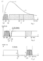
- the frequency-reduced quadrature-modulated color carrier F is recorded in the lower frequency range with a frequency of 0.63 MHz and a bandwidth of approximately ⁇ 500 kHz.
- the video signal V is recorded by FM of an image carrier. Its static modulation characteristic extends between the frequencies 3.8 and 4.8 MHz, where 3.8 MHz corresponds to the ultra black level and 4.8 MHz to the white level of the video signal. The modulation results in a frequency spectrum of 1.3 to 7.3 MHz. Due to the head gap, the upper sideband (above 6 MHz) is not scanned completely, so that interference from signal reflections is reduced. Sound signals are not included in the known spectrum. They are prepared separately in known devices and recorded in a track running along the band edge.
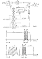
- the two luminance and chrominance signal spectra are shown enlarged in FIG. 2, the position of the sound signals introduced by the invention being indicated.
- two sound carriers 1 and 2 each modulated with an LF sound signal in FM, are recorded at the frequencies 1.07 and 1.31 MHz. If a stereo signal is introduced on the transmitter side, which has a spacing of the FM sound carriers of 250 kHz, then the carriers 1, 2 should also have a corresponding spacing for the purpose of simple implementation which is favorable for quality improvement.
- the two LF audio signals can represent a mono signal, a stereo signal or a sound signal in different languages.
- the frequencies of the two sound carriers 1, 2 are approximately at the maximum 4 of the head-band frequency response characteristic 5, which is effective when recording the entire signal on the helical tracks.
- FIG. 3 shows in the normal frequency spectrum of the television signal the bandwidth losses of the luminance signal and of the chrominance signal introduced by the invention.
- the loss of the chrominance signal at D is 0.06 MHz.
- the loss of the luminance signal is 0.10 MHz.
- the loss of resolution of the luminance signal is ver negligible and the single sideband error of the chrominance signal not noticeable.
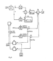
- the CVBS signal in the circuit 6 is separated by frequency-selective means into the modulated color carrier F and the luminance signal Y (luminance signal).
- the modulated PAL color carrier F (chrominance signal) is converted in the frequency converter 7 from its original frequency 4.43 MHz to the frequency 0.63 MHz and via a notch filter N1, which is a filter with an extremely steep edge for shifting the upper edge of the chrominance band, the adder 8 fed.
- the luminance signal Y is modulated onto an image carrier in the frequency modulator 9, as a result of which a frequency spectrum of 1.3 to 7.3 MHz according to FIG. 1 is produced. In this frequency spectrum, the lower edge of the luminance band is shifted upward in the circuit 10 by a notch filter, not shown.
- the signal remaining as a result is also fed to the adder 8.
- Two sound signals NF1 and NF2, e.g. B. from a microphone input two carriers with the frequency of 1.07 and 1.31 MHz are modulated in two frequency modulators 11, 12, which are also supplied to the adder 8.
- an FM hub of ⁇ 50 kHz is selected, which results in modulation bandwidths of 1.07 or 1.31 MHz ⁇ 70 kHz.
- the frequencies of the two sound carriers according to FIG. 2 are suppressed in the circuit 10 by the notch filter mentioned.
- the output signal of the adder 8 contains the signals shown in FIG.
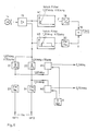
- Mixers or modulators M1 and M2 are provided for recording sound signals, such as those broadcast by television stations and received by a tuner T, which mix the received modulated sound carriers 1 and convert them to intermediate frequencies ZF1 (5.5 MHz) and ZF2 (5.742 MHz) , 2 implement while maintaining the high frequency to frequencies of 1.07 and 1.31 MHz.
- a quartz-stabilized reference frequency source R is provided with a frequency of 4.43 MHz, which can be the color carrier reference oscillator already present in PAL devices.
- the IC MM 1496 (Motorola) has proven itself as a mixer.
- the output terminals of the mixers M1 and M2 are connected to the adder via switches S1 and S2, so that the device can optionally be switched to the LF audio signal and the RF audio signal.
- the source R can also be a separate oscillator.
- FIG. 5 shows a modification of FIG. 4.
- the difference lies in the use of a single notch filter N for chrominance and luminance channels, which is shown in detail in FIG. 10.
- the output signals of the frequency converter 7 and the filter circuit 10 are fed to an adder 8, to which, in contrast to FIG. 4, the sound signals are not fed.
- the output of the adder 8 is fed to the notch filter N and from there to another adder 8a, to which the sound signals from the switches S1 and S2 are also fed.
- FIG. 6 shows a circuit for reproducing the recorded spectrum according to FIG. 2.
- the signal sampled alternately by the heads 14a, 14b is amplified in an amplifier 15 and split into the chrominance channel and the luminance channel with separate notch filters N1 and N2.
- Demodulators 18 and 20 demodulate these signals and pass the demodulated signals to an adder circuit 19, in which the CVBS signal is recovered. Further processing takes place in the usual, known manner.
- the sound signal is split off in front of the inputs of the notch filters N1, N2 and fed via filters 21, 22 to two mixers M1, M2, which recover the sound IF signals Tone ZF1, Tone ZF2 by means of the reference frequency of the source R.
- These IF signals can be fed to the receiver directly or via renewed conversion into the reception channels of the VHF / UHF band.
- the sampled audio signals can also be demodulated directly if this is required in the recorder.
- the signal mixture according to FIG. 1, which is alternately sampled by the heads 14a, 14b, is amplified in the amplifiers 15a and 15b and freed of the audio signal via the notch filter N and via filters 16, 17 in the modulated color carrier F and split the modulated image carrier Y Fm . Since the change between the heads 14a, 14b takes place during the duration of the vertical blanking interval, no additional measures with regard to the video signals are required, apart from a hard electronic switch 27 for the head signals of the amplifier outputs 15a and 15b for a correct color conversion and FM demodulation. The color carrier F is converted back to the frequency of 4.43 MHz in the frequency converter 18 and fed to the adder 19.
- the luminance signal Y is obtained in the frequency demodulator 20 and supplied to the adder 19.
- the overall signal mix provided by heads 14a and 14b has overlap zones in which both heads 14a, 14b are in contact with the tape and deliver output signals. These overlapping zones form a soft electronic cross-fading device for the sound carrier signals.
- the entire signal mixture supplied by the heads 14a, 14b is branched off before any circuit for linearizing the envelope curve of the video signal mixture supplied by the heads or before any device for hard electronic cross-fading.
- the two modulated sound carriers are selectively separated from the signal mixture according to FIG. 2 using narrow-band filters 21, 22 and fed to mixers M1, M2.
- the mixers deliver the two tone signals tone ZF1 and tone ZF2.
- the total signal supplied by the head 14a or by the amplifier 15a is fed to an adder 25 before being fed to the demodulators 23, 24.
- the total signal supplied by the head 14b or by the amplifier 15b is fed to an amplifier 26, the output signal of which is also fed to the adder 25.
- the output signal of the adder now has a signal with a sound signal component even during the switchover phase of the heads, so that the otherwise inevitable 50 Hz interference cannot occur.
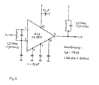
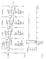
- FIG. 9 shows an example which is suitable as a filter 21, 22 and at the same time as an amplifier for the FM tone IF signals.
- a component can, for. B. can be realized using the RCA broadband amplifier IC's CA 3011.
- frequencies for sound carriers and reference carriers are given as examples. In practice, depending on the type of application, both the exact values specified in the standard and simplified values (e.g. 5.742 187 5 MHz or only 5.74 MHz for the audio signal NF2) can be used.
- a quartz-stabilized PAL reference oscillator with a frequency of 4.433 618 MHz ⁇ 1 kHz was used as the reference carrier source R, but in most cases the accuracy can be set to be lower than that for decoding of the PAL signals is required. The accuracy must be so great that the demodulation takes place in the linear range of the demodulator characteristic.
- the CVBS signal is fed to amplifier 41.
- This delivers the modulated PAL color carrier F with a frequency of 4.43 MHz. This frequency is reduced in the frequency converter 42 to a frequency of 0.63 MHz.
- the color carrier which is thus reduced in frequency, is fed to the adder 43.
- the amplifier 41 also supplies the luminance signal Y, which is modulated onto an image carrier in the frequency modulator 44. This arrives at the filter 45, which passes the frequency spectrum at the output of the modulator 44, but has two blocking points therein at the frequencies 1.7 and 1.9 MHz.
- the image carrier Y-FM frequency-modulated with the Y signal is also fed to the adder 43.
- a first sound signal NF1 is fed to the FM modulator 46, which generates a first sound carrier with the frequency of 1.7 MHz.
- a second sound signal NF2 is fed to the second FM modulator 47, which generates a second sound carrier with the frequency of 1.9 MHz.
- the two sound carriers are also fed to the adder 43.
- This signal is fed to the video head 14 and recorded on the magnetic tape 28. In practice there are generally two video heads which record fields one after the other on inclined tracks 29 of the magnetic tape 28.
- Signal NF1 is also fed to flip-flop 50 with a threshold characteristic. If the instantaneous value of the signal NF1 exceeds a certain value, a manipulated variable arises at the output of the stage 50, which increases the blocking bandwidth at the frequency of 1.7 MHz in the filter 45. The frequency range which is suppressed in the filter 45 at the frequency of 1.7 MHz thus becomes the respective amplitude of the signal NF1 adjusted. In the same way, the sound signal NF2 is fed to stage 51. Their output voltage controls the bandwidth of the suppression in the filter 45 at the frequency of 1.9 MHz.
- FIG. 14 shows the blocking bandwidth 52 for the sound carrier at 1.7 MHz and the blocking bandwidth 53 for the sound carrier at 1.9 MHz, in relation to the base frequency band of the Y signal.
- the controllable filter would then lie in the path of the Y signal, that is to say in front of the modulator 44, so that the frequency components do not arise in the region of the two sound carriers during modulation in the modulator 44.
- the blocking bandwidths 52, 53 shown are therefore not constant, but are dependent on the respective amplitude of the audio signals NF1 and NF2.
- FIG. 15 shows the frequency carrier F which is reduced in frequency and the frequency spectrum of the modulated image carrier Y-FM at the output of the filter 45.
- the blocking bandwidths 52, 53 shown with the frequencies shown thus apply to the maximum amplitude of the audio signals NF1, NF2 and become lower as the frequency decreases Amplitude reduced accordingly.
- the static modulation characteristic of the modulator 44, which effects the frequency spectrum according to FIG. 15, lies between the frequencies 3.8 MHz for the black level and 4.8 MHz for the white level of the video signal Y.
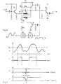
- FIG. 16 shows an example of a circuit for the controllable filter 45 in FIG. 13.
- the signal Y-FM is fed via the emitter follower transistor stage 54 to the resonant circuit 55, which is tuned to the frequency of 1.7 MHz or 1.9 MHz, and is supplied via another Emitter follower stage 56 is connected to the output terminal leading to adder 43.
- the inductance of the blocking circuit 55 consists of the two mutually identical windings 57, 58, which are designed as a bifilar winding.
- the connection point of the windings 57, 58, i.e. H. the center tap of the inductance of the blocking circuit is connected to earth via the adjustable resistor 59 and the resistor 60.
- Transistor 61 is connected in parallel with resistor 60.
- the resistor 62 and a further resistor 63 are also connected in parallel with the resonant circuit 55 via the transistor 64.
- the control of the filter according to FIG. 16 is explained with reference to FIG. 17. If the sound signal NF1 according to FIG. 17a lies below the threshold value U s , the transistors 61, 64 are blocked. The resistor 63 is then ineffective for damping the resonant circuit 55. The resistor 60 is not bridged, so that the connection point of the windings 57, 58 is grounded at high resistance. The filter now has its minimum blocking bandwidth at 1.7 MHz according to FIG. 17c.
- the flip-flop 65 is triggered and generates a pulse according to FIG. 17b, which reaches the bases of the transistors 61, 64 via the amplifier 66.
- the transistor 61 then bridges the resistor 60, so that the connection point of the windings 57, 58 is now grounded via the resistor 59 with low resistance.
- the transistor 64 also becomes conductive and switches the resistor 63 in parallel with the blocking circuit, so that its damping is increased. This stronger damping of the blocking circuit 55 results in an enlarged blocking bandwidth according to FIG. 17d, which is adapted to the larger amplitude of the signal NF1.
- the blocking bandwidth 53 is controlled in the same way with a further filter according to FIG. 17, only for the other frequency of 1.9 MHz.
- the blocking bandwidth is switched between two values according to FIGS. 17c and 17d. Continuous control of the blocking bandwidths 52, 53 by the amplitude of the sound signal NF1 or NF2 is also possible. It is also possible to supply the sound signal to a rectifier or a filter element, to obtain a manipulated variable obtained from the mean amplitude and to use this manipulated variable to control the blocking bandwidth 52 or 53.
Landscapes
- Engineering & Computer Science (AREA)
- Multimedia (AREA)
- Signal Processing (AREA)
- Television Signal Processing For Recording (AREA)
Claims (20)
Applications Claiming Priority (2)
| Application Number | Priority Date | Filing Date | Title |
|---|---|---|---|
| DE19813121600 DE3121600A1 (de) | 1981-05-30 | 1981-05-30 | Videorecorder mit verbesserter aufzeichnung des tonsignals |
| DE3121600 | 1981-05-30 |
Publications (3)
| Publication Number | Publication Date |
|---|---|
| EP0066067A2 EP0066067A2 (fr) | 1982-12-08 |
| EP0066067A3 EP0066067A3 (en) | 1984-08-08 |
| EP0066067B1 true EP0066067B1 (fr) | 1986-12-03 |
Family
ID=6133599
Family Applications (1)
| Application Number | Title | Priority Date | Filing Date |
|---|---|---|---|
| EP82103094A Expired EP0066067B1 (fr) | 1981-05-30 | 1982-04-10 | Enregistreur vidéo avec enregistrement de plusieurs porteuses de son et d'une porteuse d'image sur une piste d'enregistrement |
Country Status (2)
| Country | Link |
|---|---|
| EP (1) | EP0066067B1 (fr) |
| DE (2) | DE3121600A1 (fr) |
Families Citing this family (10)
| Publication number | Priority date | Publication date | Assignee | Title |
|---|---|---|---|---|
| JPS58121882A (ja) * | 1982-01-16 | 1983-07-20 | Sony Corp | 映像及び音声信号再生装置 |
| JPH0732487B2 (ja) * | 1982-02-17 | 1995-04-10 | 株式会社日立製作所 | 映像信号および音声信号の記録回路 |
| DE3205781C1 (de) * | 1982-02-18 | 1983-10-06 | Licentia Gmbh | Videorecorder mit Zeitraffer- und/oder Zeitlupenwiedergabe |
| DE3237901A1 (de) * | 1982-10-13 | 1984-07-19 | Telefunken Fernseh Und Rundfunk Gmbh, 3000 Hannover | Videorecorder mit aufzeichnung eines ersten und eines zweiten tontraegers |
| DE3238231A1 (de) * | 1982-10-15 | 1984-08-02 | Telefunken Fernseh Und Rundfunk Gmbh, 3000 Hannover | Videorecorder mit aufzeichnung eines tontraegers |
| DE3305103C2 (de) * | 1983-02-15 | 1984-11-29 | Telefunken Fernseh Und Rundfunk Gmbh, 3000 Hannover | Videorecorder mit verbesserter Aufzeichnung des Tonsignals |
| DE3306978A1 (de) * | 1983-02-28 | 1984-08-30 | Telefunken Fernseh Und Rundfunk Gmbh, 3000 Hannover | Videorecorder mit aufzeichnung eines frequenzmodulierten tontraegers |
| JPS60199283A (ja) * | 1984-03-24 | 1985-10-08 | Sony Corp | 磁気記録再生装置 |
| DE3608796A1 (de) * | 1986-03-15 | 1987-09-17 | Thomson Brandt Gmbh | Videorecorder mit verbesserter tonaufzeichnung |
| DE3613473A1 (de) * | 1986-04-22 | 1987-10-29 | Thomson Brandt Gmbh | Videorecorder mit verbesserter tonwiedergabe |
Family Cites Families (6)
| Publication number | Priority date | Publication date | Assignee | Title |
|---|---|---|---|---|
| DE1277900B (de) * | 1965-03-23 | 1968-09-19 | Loewe Opta Gmbh | Verfahren zum magnetischen Aufzeichnen und Wiedergeben von hochfrequenten Signalen, insbesondere von Fernsehbildsignalen, sowie von Ton- und/oder Synchronsignalen |
| GB1214328A (en) * | 1967-11-03 | 1970-12-02 | Iit Res Inst | Improvements in or relating to recording |
| US3806638A (en) * | 1971-06-24 | 1974-04-23 | Itt Research Institute | Offset carrier recording system & method |
| DE2201691A1 (de) * | 1972-01-14 | 1973-07-26 | Blaupunkt Werke Gmbh | Verfahren zur simultanen aufzeichnung und wiedergabe von farb-fernsehsignalen |
| GB1560991A (en) * | 1975-12-08 | 1980-02-13 | Rca Corp | Video record player system |
| DE3113862A1 (de) * | 1981-04-06 | 1982-10-21 | Licentia Patent-Verwaltungs-Gmbh, 6000 Frankfurt | Videorecorder zur aufzeichnung eines mit dem videosignal frequenzmodulierten bildtraegers |
-
1981
- 1981-05-30 DE DE19813121600 patent/DE3121600A1/de not_active Withdrawn
-
1982
- 1982-04-10 DE DE8282103094T patent/DE3274611D1/de not_active Expired
- 1982-04-10 EP EP82103094A patent/EP0066067B1/fr not_active Expired
Also Published As
| Publication number | Publication date |
|---|---|
| DE3121600A1 (de) | 1982-12-23 |
| EP0066067A2 (fr) | 1982-12-08 |
| DE3274611D1 (en) | 1987-01-15 |
| EP0066067A3 (en) | 1984-08-08 |
Similar Documents
| Publication | Publication Date | Title |
|---|---|---|
| EP0061050B1 (fr) | Enregistreur vidéo pour l'enregistrement d'une porteuse d'image modulée en fréquence par un signal vidéo | |
| DE3209422A1 (de) | Magnetaufzeichnungs- und/oder -wiedergabegeraet | |
| EP0068188B1 (fr) | Enregistreur video avec un enregistrement amélioré du signal de son | |
| EP0066067A2 (fr) | Enregistreur vidéo avec enregistrement de plusieurs porteuses de son et d'une porteuse d'image sur une piste d'enregistrement | |
| EP0063737B1 (fr) | Enregistreur vidéo avec une reproduction de son amelioré | |
| DE3245434A1 (de) | Video- und audiosignal-aufnahme/wiedergabe-einrichtung | |
| EP0062783B1 (fr) | Magnétoscope avec traitement d'une ou de plusieurs porteuses de son modulées | |
| DE3113862A1 (de) | Videorecorder zur aufzeichnung eines mit dem videosignal frequenzmodulierten bildtraegers | |
| DE3642217C2 (fr) | ||
| DE2156305C2 (de) | Gerat zur Aufzeichnung und/oder Wie dergabe eines Fernsehsignals, insbesondere fur eine Bildplatte | |
| DE3314782C2 (fr) | ||
| DE3730135C2 (fr) | ||
| DE3303861A1 (de) | Videobandgeraet | |
| DE3122754C2 (de) | Videorecorder mit verbesserter Tonwiedergabe | |
| EP0130437A2 (fr) | Enregistreur vidéo avec l'enregistrement d'un ou plusieurs signaux de son | |
| DE2256543B2 (de) | Schaltungsanordnung zur Aufzeichnung und Wiedergabe eines Farbfernsehsignalgemischs auf bzw. von einem Aufzeichnungsträger | |
| DE3725683C2 (de) | Aufzeichnungsgerät für Videosignale | |
| DE3110142C2 (fr) | ||
| DE3029931C2 (de) | Einrichtung zum Aufzeichnen von Fernsehbildern | |
| DE3153617C2 (en) | Helical scan VTR audio recording method | |
| DE3305103C2 (de) | Videorecorder mit verbesserter Aufzeichnung des Tonsignals | |
| DE3116130A1 (de) | Videorecorder mit verbesserter tonwiedergabe | |
| DE3133929A1 (de) | Videorecorder mit aufzeichnung von tonsignalen, insbesondere fuer stereoton | |
| DE3135807A1 (de) | Videorecorder mit aufzeichnung von zwei tonsignalen, insbesondere fuer stereoton | |
| DE3135809A1 (de) | Videorecorder mit aufzeichnung von tonsignalen, insbesondere fuer stereoton |
Legal Events
| Date | Code | Title | Description |
|---|---|---|---|
| PUAI | Public reference made under article 153(3) epc to a published international application that has entered the european phase |
Free format text: ORIGINAL CODE: 0009012 |
|
| AK | Designated contracting states |
Designated state(s): BE DE FR GB IT SE |
|
| 17P | Request for examination filed |
Effective date: 19830427 |
|
| PUAL | Search report despatched |
Free format text: ORIGINAL CODE: 0009013 |
|
| AK | Designated contracting states |
Designated state(s): BE DE FR GB IT SE |
|
| RAP1 | Party data changed (applicant data changed or rights of an application transferred) |
Owner name: TELEFUNKEN FERNSEH UND RUNDFUNK GMBH |
|
| ITF | It: translation for a ep patent filed | ||
| GRAA | (expected) grant |
Free format text: ORIGINAL CODE: 0009210 |
|
| AK | Designated contracting states |
Kind code of ref document: B1 Designated state(s): BE DE FR GB IT SE |
|
| REF | Corresponds to: |
Ref document number: 3274611 Country of ref document: DE Date of ref document: 19870115 |
|
| ET | Fr: translation filed | ||
| PLBE | No opposition filed within time limit |
Free format text: ORIGINAL CODE: 0009261 |
|
| STAA | Information on the status of an ep patent application or granted ep patent |
Free format text: STATUS: NO OPPOSITION FILED WITHIN TIME LIMIT |
|
| 26N | No opposition filed | ||
| ITTA | It: last paid annual fee | ||
| PGFP | Annual fee paid to national office [announced via postgrant information from national office to epo] |
Ref country code: GB Payment date: 19920331 Year of fee payment: 11 |
|
| PGFP | Annual fee paid to national office [announced via postgrant information from national office to epo] |
Ref country code: SE Payment date: 19920415 Year of fee payment: 11 |
|
| PGFP | Annual fee paid to national office [announced via postgrant information from national office to epo] |
Ref country code: BE Payment date: 19920423 Year of fee payment: 11 |
|
| PGFP | Annual fee paid to national office [announced via postgrant information from national office to epo] |
Ref country code: FR Payment date: 19920429 Year of fee payment: 11 |
|
| PGFP | Annual fee paid to national office [announced via postgrant information from national office to epo] |
Ref country code: DE Payment date: 19920624 Year of fee payment: 11 |
|
| PG25 | Lapsed in a contracting state [announced via postgrant information from national office to epo] |
Ref country code: GB Effective date: 19930410 |
|
| PG25 | Lapsed in a contracting state [announced via postgrant information from national office to epo] |
Ref country code: SE Effective date: 19930411 |
|
| PG25 | Lapsed in a contracting state [announced via postgrant information from national office to epo] |
Ref country code: BE Effective date: 19930430 |
|
| BERE | Be: lapsed |
Owner name: TELEFUNKEN FERNSEH UND RUNDFUNK G.M.B.H. Effective date: 19930430 |
|
| GBPC | Gb: european patent ceased through non-payment of renewal fee |
Effective date: 19930410 |
|
| PG25 | Lapsed in a contracting state [announced via postgrant information from national office to epo] |
Ref country code: FR Effective date: 19931229 |
|
| PG25 | Lapsed in a contracting state [announced via postgrant information from national office to epo] |
Ref country code: DE Effective date: 19940101 |
|
| REG | Reference to a national code |
Ref country code: FR Ref legal event code: ST |
|
| EUG | Se: european patent has lapsed |
Ref document number: 82103094.7 Effective date: 19931110 |