EP0066085A1 - Fichier sur disques magnétiques et procédé d'enregistrement et de lecture - Google Patents
Fichier sur disques magnétiques et procédé d'enregistrement et de lecture Download PDFInfo
- Publication number
- EP0066085A1 EP0066085A1 EP82103550A EP82103550A EP0066085A1 EP 0066085 A1 EP0066085 A1 EP 0066085A1 EP 82103550 A EP82103550 A EP 82103550A EP 82103550 A EP82103550 A EP 82103550A EP 0066085 A1 EP0066085 A1 EP 0066085A1
- Authority
- EP
- European Patent Office
- Prior art keywords
- tracks
- track
- physical
- logical
- frequency
- Prior art date
- Legal status (The legal status is an assumption and is not a legal conclusion. Google has not performed a legal analysis and makes no representation as to the accuracy of the status listed.)
- Ceased
Links
- 238000000034 method Methods 0.000 title claims abstract description 12
- 230000002463 transducing effect Effects 0.000 title claims abstract description 9
- 230000004044 response Effects 0.000 claims description 11
- 238000013523 data management Methods 0.000 description 3
- 238000013500 data storage Methods 0.000 description 2
- 230000001360 synchronised effect Effects 0.000 description 2
- 230000009471 action Effects 0.000 description 1
- 230000008901 benefit Effects 0.000 description 1
- 238000010586 diagram Methods 0.000 description 1
- 230000000694 effects Effects 0.000 description 1
- 230000026676 system process Effects 0.000 description 1
Images

Classifications
-
- G—PHYSICS
- G11—INFORMATION STORAGE
- G11B—INFORMATION STORAGE BASED ON RELATIVE MOVEMENT BETWEEN RECORD CARRIER AND TRANSDUCER
- G11B5/00—Recording by magnetisation or demagnetisation of a record carrier; Reproducing by magnetic means; Record carriers therefor
- G11B5/012—Recording on, or reproducing or erasing from, magnetic disks
-
- G—PHYSICS
- G11—INFORMATION STORAGE
- G11B—INFORMATION STORAGE BASED ON RELATIVE MOVEMENT BETWEEN RECORD CARRIER AND TRANSDUCER
- G11B20/00—Signal processing not specific to the method of recording or reproducing; Circuits therefor
- G11B20/10—Digital recording or reproducing
- G11B20/12—Formatting, e.g. arrangement of data block or words on the record carriers
- G11B20/1217—Formatting, e.g. arrangement of data block or words on the record carriers on discs
- G11B20/1258—Formatting, e.g. arrangement of data block or words on the record carriers on discs where blocks are arranged within multiple radial zones, e.g. Zone Bit Recording or Constant Density Recording discs, MCAV discs, MCLV discs
Definitions
- This invention relates to magnetic disk files and methods of transducing concentric physical tracks on a rotating magnetic disk.
- each disk having a plurality of concentric recording tracks on which fixed or variable length records are recorded.
- the amount of data stored on each track is the same regardless of its actual physical length, because one basic recording frequency is employed to record data on all tracks.
- Those persons having ordinary skill in the art of storing data on disk files understand and appreciate the advantage of having data tracks of equal known byte capacity where system considerations of data management are involved. Where each track of the system has the same capacity, the overall problems of where data is to be stored in the file is considerably simplified.
- the prior art does suggest the recording of data at different frequencies on different tracks on the same disk so as to increase the overall storage capacity of the disk.
- Such systems have not met with commercial acceptance because of the problems of additional overhead required of the rest of the system to manage the placement of: data in the file.
- the present invention eliminates the data management problems encountered with prior art systems.
- a magnetic disk file including at least one rotatable disk having a plurality N of groups of concentric physical recording tracks, a plurality N of magnetic transducers each of which-is associated with a different group of tracks and which are positionable conjointly to selected tracks in different groups in response to an externally supplied address signal, means for generating a plurality N of different recording frequencies which control the linear recording densities in tracks of the respective groups whereby the byte capacity per track of the groups of tracks differ, at least one logical track (LT01) including a first portion on a physical track (PT1) of one group and a second portion on a corresponding physical track (PT2) of another gruup, and means for switching from one recording frequency to another in response to sensing an index signal transduced from the file at the end of transducing the first portion, whereby the portions may be transduced in a continuous operation.
- LT01 logical track
- the invention extends to a method of transducing concentric physical tracks in a plurality N of groups on a rotating magnetic disk, which groups of tracks are recorded at ditferent frequencies that result in each track of the different groups having a different byte capacity, the method comprising conjointly positioning a plurality N of transducers to selected physical tracks in different groups in response to a single address signal, and transducing each physical track in turn with a transducer at a corresponding frequency, including sensing the end of each physical track and, in response to such sensing, switching from one transducer and frequency to another transducer and frequency.
- data is recorded in the file, for example, at two separate frequencies such that each track in an inner bana of concentric tracks that are serviced by one read/write transducer stores X bytes, while each track in an outer band of concentric tracks that are serviced by a second read/write transducer, which is moved in unison with the first transducer, stores Y bytes of data.
- the system processes records stored on equal length logical tracks which have a length equal to (X+Y)/Z, where Z is an integor of 1 or greater so that at least one logical record has a first part recorded at one frequency and a second part recorded at the other frequency.
- the system is arranged such that at each physical address of the transducer positioning system, the recording or reading operation involves switching f L om one transducer to the other at the index point on the disk, resyncing the recording channel to the new frequency and continuing to record or read the logical track that was started prior to index.
- an object of the present invention to provide an improved system and method for storing data in a disk file at more than one frequency.
- Another object of the present invention is to provide an improved method for reading and recoraing data at two or more separate frequencies in a disk file to increase overall storage capacity without causing data management problems.
- a further object of the present invention is to provide a data storage system for a disk file in which at least two separate physical tracks having different storage capacities are read or written consecutively on successive revolutions of the disk, and the resulting data is converted to one or more equal capacity logical tracks. At least one logical track, therefore, has a first portion recorded at one frequency and a second portion recorded at a second frequency.
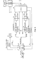
- a magnetic disk file (Fig.l) comprises a magnetic recording disk 10, a pair of magnetic read/write transducers 11 and 12, means 13 for conjointly positioning the transducers 11 and 12 to selected concentric recording tracks 14, and means (not shown) for rotating the disk 10.
- One group 16 of tracks is associated with transducer 11 while the other group 17 of tracks is associated with transducer 12.
- Transducers 11 and 12 are positionable conjointly by positioning means 13 in response to a track address supplied to an address register 19 of the positioning means 13. All the tracks of group 16, which are serviced by transducer 11, are recorded under the control of a clocking signal having a frequency fl. All the tracks of group 17, which are serviced by transducer 12, are recorded under a clocking signal having a frequency f2, which is higher than fl.
- all the tracks in group 16 have the same storage capacity Cl, measured in terms of the number of byte positions.
- all the tracks in group 17 have the same storage capacity C2, also measured in number of byte positions, and C2 will have a relationship to Cl which is similar to the relationship of f2 to fl.
- Cl storage capacity
- C2 storage capacity
- f2 is equal to 1.4 x fl.
- Fig. 2 illustrates how a pair of physical tracks PT1 and PT2 associated with one address position of the positioning means are formatted into, for example, three logical tracks LTO, LT01, anu LTl.
- LTO physical tracks
- LT01 an address position of the positioning means
- PT1 has a 20,000 byte capacity
- PT2 has a 28,000 byte capacity
- each logical track LT has a byte capacity of 16,000 bytes.
- the manner in wnich each logical track is actually formatted will depend on the system nvironment and the details thereof are not part of the present invention. Any format known in the ar L for formatting tracks into blocks, segments or count-key-and-data records may be employed. Therefore, no details of the record format of the logical track is included in this description of he invention.
- Fig.2 shows physical tracks PT1 and PT2 divided into three logical tracks, it should be understood that the two tracks could be combined as one logical track ot 48K bytes, two logical tracks of 24K bytes, four logical tracks of 12K bytes, etc.
- the recording channel comprises a serialiser-deserialiser SERDES 30 whose function is to serialize the parallel-by-bit, serial-by-byte data supplied from a data processing system (not shown) via bus 31.
- Serializer 30 also deserializes seriaL-by-bit data from the file tu supply parallel-by-bit, serial-by-byte data to the data processing system.
- Serial-by-bit write data is supplied to the write driver 32 on write data lines 33 and 34.
- Write data line 33 supplies write data at frequency fl which corresponds to the frequency of variable frequency oscillator 36 which is associated with the group 16 of tracks serviced by transducer 11 corresponding o the inner band or recording tracks.
- the write data line 34 supplies write data at frequency f2 wnich corresponds to the frequency or variable frequency oscillator 37 which is associated with the group 17 of tracks serviced by transducer 12 in the outer band of recording tracks. While two variable frequency oscillators are shown, one device which performs both functions may be employed.
- Variable frequency oscillators 36 and 37 are synchronized by signals from a phase-locked oscillator which is synchronized to the rotation of the disk file, as is well known in the art.
- the write driver 32 is selected by a read/write logic signal which indicates a write or read operation for one of the heads.
- One of the two transducers is selected by the ID/OD select signal. This latter signal is switched at index by the output of AND-gate 51 from transducer 11 to transducer 12.whenever a logical track spanning index (that is a logical track divided between two physical tracks) is addressed by the system. Index is a signal transduced from the disk file at the beginning of each physical track.
- the transducers 11 and 12 are also connected to a preamplifier 42 which provides raw read data to a pair of data detectors 44 and 45, one of which is associated with each head.
- Data detector 44 is selected by the "ID" select line 46 while data detector 45 is selected by the "OD” select line 47.
- the output of the data detector 44 is supplied to the oscillator 36 which provides standardized data and a double frequency clock signal to SERDES 30 on the assumption that data was initially encoded and recorded on the file in one of the known double frequency self-clocking codes.
- Data detector 45 likewise is connected to oscillator 37 to provide similar signals to SERDES 30.
- serial-by-byte data supplied to SERDES 30 comprises both format type data and actual data bytes from the system, and that each logical track is formatted as a conventional count-key-and-data record permitting variable length data records in each of the tracks.
- SERDES is loaded under the control of the system with appropriate format data which determines the count-key-and-data fields along with the respective Gl, G2 and G3 gaps, such that three separate logical tracks are stored on two physical tracks corresponding to one address of the transducer positioning system.
- a signal is generated each time a predetermined number of byte portions has been transduced corresponding to the capacity of each logical track.
- the first logical track LTO of 16K bytes of data is recorded at frequency fl in the inner physical track PT1.
- Writing of the second logical track LT01 then begins with 4K bytes of data at frequency fl in the physical track PT1.
- the end of the inner physical track PT1 being serviced by transducer 11 is sensed, an index signal generated and the ID/OD select line switched to actuate transducer 12 which records the remaining 12K bytes of data of the second logical track LT01 on the outer physical track PT2 at the frequency f2, because the write data is now being supplied at frequency f2 which is higher than fl.
- the third logical track LT1 is stored on the second physical track PT2 after the 12K bytes of data are recorded for the second logical track LT01.
- the overall result is as shown in Fig.2. That is, three logical tracks LTO, LT01 and LT1, each having the same capacity, have been stored on two separate physical tracks and are recorded at two separate frequencies to optimize their respective storage capacities.
- a similar operation occurs when data is read, the appropriate switching action occurring at the end of the first physical track so that if the second logical track LT01 is being accessed, 4K bytes of data are read from the inner track PT1 at frequency fl, while 12K bytes of data are read from the outer track PT2 at frequency f2.
- the accessing of a non-overlapping logical track of less than a physical track in length is accomplished in a manner similar to conventional prior art systems in which the logical track corresponds exactly to the physical track, or at least in systems where a logical track does not split between two physical tracks recorded at different frequencies.
- the disk could be divided into three groups of tracks and the positioning system provided with three separate but conjointly positioned transducers to record data at frequencies fl, f2 and f3, respectively, such that three physical tracks would be addressed at one position to provide one or more logical tracks of equal length. Where two or more logical tracks occur, the length or capacity of one logical track would be a submultiple of the total length or capacity of the three physical tracks.
- the concept disclosed may be extended to include more than one disk surface since it is conventional in today's disk file configurations employing more than one recording surface to provide transducers which are permanently associated with each recording surface of the disk file.
- the system could be arranged, for example, first to operate on the inside track on one disk surface, then, at the end of the first revolution to switch from the inside track to the outside track of the one disk surface as previously described, then, at the end of the second revolution, to switch to the outside track on another disk surface, and, at the end of the third revolution, to switch to the inside track of the other surface, so that at the end of the operation four physical tracks have been concatenated.
- five logical tracks of 60K bytes could be stored on four physical tracks where the inner tracks have a capacity of 65K bytes and the outer tracks a capacity of 85K bytes.
Landscapes
- Engineering & Computer Science (AREA)
- Signal Processing (AREA)
- Signal Processing For Digital Recording And Reproducing (AREA)
Applications Claiming Priority (4)
| Application Number | Priority Date | Filing Date | Title |
|---|---|---|---|
| US26841481A | 1981-05-29 | 1981-05-29 | |
| US06/364,121 US4432025A (en) | 1981-05-29 | 1982-04-06 | System and method for formatting pairs of concentric magnetic tracks of different capacity to a plurality of equal capacity logical tracks |
| US268414 | 1994-06-29 | ||
| US364121 | 1999-07-30 |
Publications (1)
| Publication Number | Publication Date |
|---|---|
| EP0066085A1 true EP0066085A1 (fr) | 1982-12-08 |
Family
ID=26953067
Family Applications (1)
| Application Number | Title | Priority Date | Filing Date |
|---|---|---|---|
| EP82103550A Ceased EP0066085A1 (fr) | 1981-05-29 | 1982-04-27 | Fichier sur disques magnétiques et procédé d'enregistrement et de lecture |
Country Status (3)
| Country | Link |
|---|---|
| US (1) | US4432025A (fr) |
| EP (1) | EP0066085A1 (fr) |
| CA (1) | CA1173956A (fr) |
Cited By (3)
| Publication number | Priority date | Publication date | Assignee | Title |
|---|---|---|---|---|
| EP0316084A3 (en) * | 1987-11-10 | 1990-10-10 | International Business Machines Corporation | Data storage apparatus |
| EP0321941A3 (fr) * | 1987-12-23 | 1991-10-30 | Konica Corporation | Procédé pour identifier des disques et configurer automatiquement le système d'entraínement |
| EP0440091A3 (en) * | 1990-01-31 | 1992-10-28 | Sony Corporation | A disk recording apparatus |
Families Citing this family (13)
| Publication number | Priority date | Publication date | Assignee | Title |
|---|---|---|---|---|
| US4811280A (en) * | 1983-06-16 | 1989-03-07 | American Telephone And Telegraph Company | Dual mode disk controller |
| US4918677A (en) * | 1985-01-23 | 1990-04-17 | Canon Kabushiki Kaisha | Information recording/reproducing apparatus including a plurality of recording or reproducing rates |
| JPS62150424A (ja) * | 1985-12-24 | 1987-07-04 | Teac Co | デ−タ記録及び/又は再生装置 |
| US4894734A (en) * | 1987-05-15 | 1990-01-16 | Maxtor Corporation | Method and apparatus for constant density recording |
| JP2585400B2 (ja) * | 1988-03-23 | 1997-02-26 | 株式会社日立製作所 | 磁気デイスク装置 |
| US5050013A (en) * | 1989-12-04 | 1991-09-17 | Seagate Technology, Inc. | Hard sectoring circuit and method for a rotating disk data storage device |
| US5671107A (en) * | 1989-12-13 | 1997-09-23 | Hitachi, Ltd. | Large capacity magnetic disc apparatus with a particular relationship between pole thickness, saturated flux density, and recording wavelength |
| US5457703A (en) * | 1990-11-21 | 1995-10-10 | Hitachi, Ltd. | Array disk system and control method thereof |
| US5202799A (en) * | 1991-06-24 | 1993-04-13 | Ibm Corporation | Logical data tracks extending among a plurality of zones of physical tracks of one or more disk devices |
| US5293565A (en) * | 1992-02-04 | 1994-03-08 | International Business Machines Corporation | Fortmat for data-storing disk media wherein addressable track angular length is independent of disk revolutions |
| JPH06349011A (ja) * | 1993-06-08 | 1994-12-22 | Sony Corp | 磁気記録装置の書き込み電流設定回路 |
| JPH07271513A (ja) * | 1994-03-29 | 1995-10-20 | Fujitsu Ltd | ディスク制御方法及びディスク制御装置 |
| US5835930A (en) * | 1996-04-09 | 1998-11-10 | International Business Machines Corporation | One or more logical tracks per physical track in a headerless disk drive |
Citations (4)
| Publication number | Priority date | Publication date | Assignee | Title |
|---|---|---|---|---|
| US3337852A (en) * | 1964-06-05 | 1967-08-22 | Honeywell Inc | Information handling apparatus |
| US3524172A (en) * | 1966-09-29 | 1970-08-11 | Burroughs Corp | Timing arrangement for generating plural phases |
| DE1774486A1 (de) * | 1961-12-07 | 1972-01-13 | Ex Cell O Corp | Magnetplattenspeicher |
| JPS55108918A (en) * | 1979-02-13 | 1980-08-21 | Fujitsu Ltd | Recording system |
Family Cites Families (2)
| Publication number | Priority date | Publication date | Assignee | Title |
|---|---|---|---|---|
| US3829837A (en) * | 1971-06-24 | 1974-08-13 | Honeywell Inf Systems | Controller for rotational storage device having linked information organization |
| US4231071A (en) * | 1978-07-17 | 1980-10-28 | Digital Equipment Corporation | Reader for data recorded on magnetic disks at plural densities |
-
1982
- 1982-04-06 US US06/364,121 patent/US4432025A/en not_active Expired - Fee Related
- 1982-04-27 EP EP82103550A patent/EP0066085A1/fr not_active Ceased
- 1982-05-26 CA CA000403711A patent/CA1173956A/fr not_active Expired
Patent Citations (4)
| Publication number | Priority date | Publication date | Assignee | Title |
|---|---|---|---|---|
| DE1774486A1 (de) * | 1961-12-07 | 1972-01-13 | Ex Cell O Corp | Magnetplattenspeicher |
| US3337852A (en) * | 1964-06-05 | 1967-08-22 | Honeywell Inc | Information handling apparatus |
| US3524172A (en) * | 1966-09-29 | 1970-08-11 | Burroughs Corp | Timing arrangement for generating plural phases |
| JPS55108918A (en) * | 1979-02-13 | 1980-08-21 | Fujitsu Ltd | Recording system |
Non-Patent Citations (2)
| Title |
|---|
| Patent Abstracts of Japan, Vol. 2, No. 125, 20 October 1978, page 7477E78 & J P-A-53 092 109 * |
| Patent Abstracts of Japan, Vol. 4, No. 160, 8 November 1980, page 136P35 & JP-A-55 108 918 * |
Cited By (4)
| Publication number | Priority date | Publication date | Assignee | Title |
|---|---|---|---|---|
| EP0316084A3 (en) * | 1987-11-10 | 1990-10-10 | International Business Machines Corporation | Data storage apparatus |
| EP0321941A3 (fr) * | 1987-12-23 | 1991-10-30 | Konica Corporation | Procédé pour identifier des disques et configurer automatiquement le système d'entraínement |
| EP0440091A3 (en) * | 1990-01-31 | 1992-10-28 | Sony Corporation | A disk recording apparatus |
| US5253124A (en) * | 1990-01-31 | 1993-10-12 | Sony Corporation | Apparatus for forming recording tracks on disks with different track-number formats |
Also Published As
| Publication number | Publication date |
|---|---|
| US4432025A (en) | 1984-02-14 |
| CA1173956A (fr) | 1984-09-04 |
Similar Documents
| Publication | Publication Date | Title |
|---|---|---|
| EP0066085A1 (fr) | Fichier sur disques magnétiques et procédé d'enregistrement et de lecture | |
| US4001883A (en) | High density data storage on magnetic disk | |
| US5822142A (en) | Method of mapping logical sectors to physical sectors in a disk drive sparing partition | |
| US4656532A (en) | Sector identification method for hard sectored hard files | |
| CA2049768A1 (fr) | Appareil d'enregistrement d'information numerique comprimee sur disque optique | |
| US4914530A (en) | Media defect management within disk drive sector format | |
| KR19980081265A (ko) | 디지털 데이터 기록 방법 및 디지털 데이터 기록 매체 | |
| KR0167587B1 (ko) | 디지털데이터기록재생장치 | |
| US5274508A (en) | Tape storage device for storing audio data in the amble frames of a DDS format tape | |
| GB2141566A (en) | Storage medium controller | |
| GB1454081A (en) | Digital data magnetic tape recording apparatus | |
| US6185058B1 (en) | No-ID data storage disk drive data sector formatting system and method | |
| GB2296598A (en) | A data format for a constant density magnetic disc apparatus | |
| JPH0458670B2 (fr) | ||
| US5361179A (en) | Data recording and/or reproducing apparatus and method | |
| US4504873A (en) | Identification field scan apparatus | |
| US4223390A (en) | System and method for attaching magnetic storage devices having dissimilar track capacities and recording formats | |
| GB1455508A (en) | Data storage system | |
| US3311891A (en) | Recirculating memory device with gated inputs | |
| KR100258403B1 (ko) | 데이타 레코더 및 그 작동방법 | |
| CA1092705A (fr) | Systeme et methode de raccordement de memoires magnetiques a nombres et configurations de piste differents | |
| CA1139434A (fr) | Appareil de controle d'enregistrement de donnees codees par groupe | |
| US3001180A (en) | Data revolving | |
| US5949599A (en) | Digital signal recording for after-recording a number of samples represented by an ID signal | |
| JPH07169185A (ja) | ディスク記憶装置のデータ読み書き方式 |
Legal Events
| Date | Code | Title | Description |
|---|---|---|---|
| PUAI | Public reference made under article 153(3) epc to a published international application that has entered the european phase |
Free format text: ORIGINAL CODE: 0009012 |
|
| AK | Designated contracting states |
Designated state(s): DE FR GB |
|
| 17P | Request for examination filed |
Effective date: 19830322 |
|
| STAA | Information on the status of an ep patent application or granted ep patent |
Free format text: STATUS: THE APPLICATION HAS BEEN REFUSED |
|
| 18R | Application refused |
Effective date: 19850430 |
|
| RIN1 | Information on inventor provided before grant (corrected) |
Inventor name: GROGAN, JOHN MATTHEW |