EP0066093B1 - Vogel-Badehaus - Google Patents
Vogel-Badehaus Download PDFInfo
- Publication number
- EP0066093B1 EP0066093B1 EP82103594A EP82103594A EP0066093B1 EP 0066093 B1 EP0066093 B1 EP 0066093B1 EP 82103594 A EP82103594 A EP 82103594A EP 82103594 A EP82103594 A EP 82103594A EP 0066093 B1 EP0066093 B1 EP 0066093B1
- Authority
- EP
- European Patent Office
- Prior art keywords
- bath according
- bird bath
- section
- guide groove
- foot
- Prior art date
- Legal status (The legal status is an assumption and is not a legal conclusion. Google has not performed a legal analysis and makes no representation as to the accuracy of the status listed.)
- Expired
Links
- 238000003287 bathing Methods 0.000 title description 2
- 238000001465 metallisation Methods 0.000 claims description 2
- XLYOFNOQVPJJNP-UHFFFAOYSA-N water Substances O XLYOFNOQVPJJNP-UHFFFAOYSA-N 0.000 claims description 2
- 239000011247 coating layer Substances 0.000 claims 1
- 238000010276 construction Methods 0.000 claims 1
- 239000002184 metal Substances 0.000 claims 1
- 239000003381 stabilizer Substances 0.000 claims 1
- 238000005452 bending Methods 0.000 description 2
- 239000004033 plastic Substances 0.000 description 2
- 239000004793 Polystyrene Substances 0.000 description 1
- 238000007792 addition Methods 0.000 description 1
- 229920005669 high impact polystyrene Polymers 0.000 description 1
- 239000004797 high-impact polystyrene Substances 0.000 description 1
- 238000003780 insertion Methods 0.000 description 1
- 230000037431 insertion Effects 0.000 description 1
- 230000003014 reinforcing effect Effects 0.000 description 1
- 230000000087 stabilizing effect Effects 0.000 description 1
Images


Classifications
-
- A—HUMAN NECESSITIES
- A01—AGRICULTURE; FORESTRY; ANIMAL HUSBANDRY; HUNTING; TRAPPING; FISHING
- A01K—ANIMAL HUSBANDRY; AVICULTURE; APICULTURE; PISCICULTURE; FISHING; REARING OR BREEDING ANIMALS, NOT OTHERWISE PROVIDED FOR; NEW BREEDS OF ANIMALS
- A01K31/00—Housing birds
- A01K31/06—Cages, e.g. for singing birds
Definitions
- the invention relates to a bird bath house, which has hooks for hanging on a cage on the front side provided with the passage opening and in which a roof part is placed on a tub part.
- the hooks are provided for hanging above the passage opening on the roof part, a guide web and the central plane of a guide groove extend in the vertical direction and protrude from a latching device in the horizontal direction Inner flank of the guide groove away through openings in the guide bar.
- the entire bath house must be removed from the cage, because. with the tub part can be cleaned or otherwise serviced, and makes it difficult to push the strong locking lugs out of the locking recesses in order to pull the roof part off the tub part, the latching device being strong, since they hold the tub part and roof part together against pulling in the vertical direction got to.
- An object of the invention is therefore to provide a bird bath house of the type mentioned, in which the roof part can be easily and easily removed from the tub part without removing the tub part from the cage.
- the invention provides, solving this problem, a bird bath house, which is characterized in that the roof part with a guide groove on both sides is pushed onto the guide web on both sides of the tub part from behind, in the region of the guide groove and guide web, a latching device and latching nose is provided , The hooks are provided for hanging below the passage opening on the tub part, the guide web, including the guide groove, is folded into a lateral, outward-facing position, and the catch and recess on a flat side of the guide web and a wall of the guide groove or on the front side of the Guide bar and the bottom of the guide groove are provided.
- the tub part Since the tub part is attached to the cage, it can remain on the cage when the roof part is removed.
- the roof section can be pulled off without the risk of the hooks breaking.
- the roof part and the tub part are held together by means of the web and the groove against train in the vertical direction, which is why the locking device is relieved of this stress.
- the locking device can be made relatively fine and gently responsive, so that the roof part is secure against unwanted pulling off, but can also be removed from the tub part without great effort and without manual pushing back of locking lugs.
- the door which is provided for closing the cage window, can be closed as soon as the roof part is pulled off the tub part.
- guide groove and guide web extend continuously over both longitudinal sides and the rear of the tub part and roof part. This promotes the tightness of the connection against water leaking outwards.
- the web is provided on the tub part and the groove on the roof part. It is particularly expedient and advantageous if the walls of the roof part and the tub part merge into one another in an aligned manner and a groove which forms the guide groove projects beyond the wall of the roof part to the outside. Now the bird can no longer bump into edges or protrusions when bathing.
- the latching recess is provided in the guide web and the latching lug is provided on the bottom of the guide groove, or if the latching lug is provided on the guide web and the latching recess on the wall of the guide groove.
- a latching device is provided on both longitudinal sides close to the front.
- the roof part and the tub part only snap into one another shortly before the pushing on is completed and unfasten particularly easily when the roof part is removed.
- a particularly expedient and advantageous embodiment is also present if the hooks protrude downward from the front of the tub part and a support strip projecting downward parallel to the hook is provided on the tub part.
- the seat of the tub part on the cage is improved and the risk of breaking the hook is further reduced.
- ledges extending over the length of the hooks can be provided. These ledges reduce the free distance between the hook or ledge and the front wall of the tub part and thus improve the fit of the tub part on the cage.
- the outside of the tub part is provided with a thin metallic covering layer applied by metallization.
- the tub part which sits permanently on the cage, is color-matched to the mostly metallic cage.
- the tub part acts like part of the cage.
- Another object of the invention is therefore to provide a bird bath house of the type mentioned, in which the seat of the hook on the roof part ceiling along the front edge can be varied to a considerable extent and the hook nonetheless unbreakable on the roof sits.
- the invention solves this problem, characterized in that two hooks are provided on the ceiling of the roof part at the front edge delimiting the passage opening, each hook is fastened to a foot with a smooth clamping slot and the hook foot over the Ceiling edge pushed to the ceiling by clamping alone and a multiple of the length of the ceiling edge is adjusted in thickness to the width of the clamping slot.
- connection of the hook with the foot and the foot with the ceiling is unbreakable to a considerably improved extent.
- Each of the two hooks along the edge of the ceiling can also be pushed on at a variety of locations and thus adapted to the respective cage conditions.
- the foot sits without latching by means of lugs that protrude into recesses, solely by means of clamping.
- the front edge strip of the roof part ceiling has a constant thickness over the entire length and width.
- the two hooks can be pushed on at any point along the edge of the ceiling.
- a stabilizing rib is provided on a flat side of the foot parallel to the clamping slot. This improves the firmness and clamping of the foot.
- clamping slot in the foot ends in a rounded widening. In this way, notch stresses are avoided, which could lead to breakage in the event of greater spreading of the limbs delimiting the clamping slot.
- clamping surfaces of the clamping slot are designed to be slightly spherical. This makes it easier to place the hook foot on the roof part ceiling.
- the hook is provided with a cavity from near the foot to just before the free end. This makes the hook lighter without sacrificing strength.
- the Vogel bathhouse consists of two mutually independent parts made of plastic, namely a roof part 1 and a tub part 2. It is roughly rectangular in a horizontal cross section.
- the tub part 2 is evenly closed all around by walls of the same height and a passage opening 3 is provided completely in the roof part and forms the front thereof.
- the backs of the roof section and the bath section are slightly inclined in opposite directions with respect to a vertical, so that the horizontal cross section of the bathhouse is greatest in the area of the joint between the roof and bath section.
- the tub part 2 has at its upper edge along the two long sides and the back a guide web 4 which is angled outwards by 90 ° with respect to the wall of the tub part.
- the roof part 1 has along its lower edge on both long sides and on the rear side a groove groove 5 which is angled outwards by 90 ° with respect to the wall of the roof part and forms a guide groove 6, into which the guide web 4 is inserted according to FIGS. 3 and 6 is.
- the guide web 4 fills the depth of the guide groove 6 completely, so that the roof part and the tub part cannot wobble against each other.
- a latching recess 8 is provided in each of the lateral areas, the depth of which corresponds to a maximum of half the depth or width of the web.
- a locking recess 8 is provided near each of the two front ends, as can be seen in FIGS. 1 and 6.
- the relatively flat or low locking lug can be pulled out of the locking recess relatively easily because of the rounding, with elastic bending of the side walls of the roof part 1 and the walls of the guide groove.
- two wide, tab-like hooks 10 are provided at a distance from one another, which merge into one another towards the bending region 11.
- the bend area 11 is corrugated on the top to give the birds a secure hold during takeoff and landing.
- the two hooks 10 protrude considerably from the bottom of the tub part 2 down out.
- a protruding ledge 12 is provided in the center of the inside of both hooks 10.
- the roof part 1 has a ceiling 13 at the top, which is of the same thickness throughout, that is to say is also of the same thickness over a front edge strip 14.
- Two hooks 15, each consisting of a hook member 16 and a foot 17, are pushed onto this edge strip 14 at a distance from one another.
- the foot 17 is approximately rectangular and has a central reinforcing rib 18 running in the direction of insertion on the upper surface.
- the foot 17 is divided over most of its dimension perpendicular to the edge strip 14 in the horizontal plane in the middle by a clamping slot 19 into which the edge strip 14 is clamped and whose width when the foot is removed is less than the thickness of the edge strip.
- the clamping slot 19 ends in a rounded widening 20 which runs parallel to the front edge of the ceiling 13.
- the foot 17 carries on the top the hook member 16, which is narrower in the direction of the front ceiling edge than the foot and extends at right angles to the front ceiling edge approximately over the entire foot.
- the dimension of the hook member 16 running at right angles to the corner edge tapers away from the foot towards the center of the hook member.
- the hook member 16 has a cavity 21 on both sides, which extends almost over the entire length of the hook member.
- the entire hook consists of a rigid, elastic plastic of high strength, e.g. B. an impact or high impact polystyrene.
- the bath house is free of additional devices, electrical devices, pumps or other additions and is therefore very light.
- latching recess 8 is provided in the guide web 4 and the latching lug 9 is provided on the bottom of the guide groove 6.
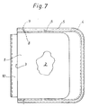
- Locking lug 9 and locking recess 8 are each rounded off in the form of a part circle.
Landscapes
- Life Sciences & Earth Sciences (AREA)
- Birds (AREA)
- Environmental Sciences (AREA)
- Zoology (AREA)
- Animal Husbandry (AREA)
- Biodiversity & Conservation Biology (AREA)
- Catching Or Destruction (AREA)
Description
- Die Erfindung betrifft ein Vogel-Badehaus, das an der mit der Durchlaß-Öffnung versehenen Vorderseite Haken zum Anhängen an einem Käfig aufweist und bei dem ein Dachteil auf ein Wannenteil aufgesetzt ist.
- Bei einem bekannten (GB-A-774557) Vogel-Badehaus dieser Art sind die Haken zum Aufhängen oberhalb der Durchlaß-Öffnung am Dachteil vorgesehen, verlaufen ein Führungssteg und die Mittelebene einer Führungsnut in vertikaler Richtung und ragen Rastnasen einer Rasteinrichtung in waagerechter Richtung von einer Innenflanke der Führungsnut weg durch Durchbrechungen des Führungssteges. Hierbei muß das gesamte Badehaus vom Käfig abgenommen werden, da. mit das Wannenteil gereinigt oder sonstwie gewartet werden kann, und macht es Schwierigkeiten, die kräftigen Rastnasen aus den Rastausnehmungen zu drücken, um das Dachteil vom Wannenteil abzuziehen, wobei die Rasteinrichtung kräftig ausgebildet ist, da sie Wannenteil und Dachteil auch gegen Zug in vertikaler Richtung zusammenhalten muß.
- Eine Aufgabe der Erfindung ist es somit, ein Vogel-Badehaus der eingangs genannten Art zu schaffen, bei dem sich der Dachteil leicht und einfach vom Wannenteil abziehen läßt, ohne den Wannenteil vom Käfig abzunehmen. Die Erfindung sieht, diese Aufgabe lösend, ein Vogel-Badehaus vor, das dadurch gekennzeichnet ist, daß das Dachteil mit beidseitiger Führungsnut auf beidseitigem Führungssteg des Wannenteiles von hinten aufgeschoben ist, im Bereich von Führungsnut und Führungssteg eine, Rastausnehmung und Rastnase umfassende Rasteinrichtung vorgesehen ist, die Haken zum Aufhängen unterhalb der Durchlaß-Öffnung am Wannenteil vorgesehen sind, der Führungssteg, samt Führungsnut, in eine seitliche, nach außen weisende Lage umgelegt ist und Rastnase und Rastausnehmung an einer Flachseite des Führungssteges und einer Wandung der Führungsnut oder an der Stirnseite des Führungssteges und dem Grund der Führungsnut vorgesehen sind.
- Da der Wannenteil am Käfig angehängt wird, kann er am Käfig bleiben, wenn der Dachteil abgenommen wird. Der Dachteil kann ohne Bruchgefahr für die Haken abgezogen werden. Der Dachteil und der Wannenteil sind mittels des Steges und der Nut gegen Zug in vertikaler Richtung zusammengehalten, weshalb die Rasteinrichtung von dieser Beanspruchung entlastet ist. Nunmehr kann die Rasteinrichtung relativ fein und sanft ansprechend ausgebildet sein, so daß der Dachteil zwar gegen ungewolltes Abziehen sicher ist, aber auch ohne großen Kraftaufwand und ohne manuelles Zurückdrücken von Rastnasen vom Wannenteil abgezogen werden kann.
- Besonders zweckmäßig und vorteilhaft ist es, wenn der obere Rand des Wannenteiles rundum in Höhe des unteren Randes der Durchlaß-Öffnung verläuft und die Biegung der Haken den unteren Rand der Durchlaß-Öffnung nach oben überragt. Bei dieser Ausbildung kann die Tür, die zum Verschließen des Käfigfensters vorgesehen ist, geschlossen werden, sobald der Dachteil vom Wannenteil abgezogen ist.
- Besonders zweckmäßig und vorteilhaft ist es weiterhin, wenn Führungsnut und Führungssteg sich ununterbrochen über beide Längsseiten und die Rückseite vom Wannenteil und Dachteil erstreckt. Hierdurch wird die Dichtigkeit der Verbindung gegen nach außen dringendes Wasser gefördert.
- In der Regel ist der Steg am Wannenteil und die Nut am Dachteil vorgesehen. Besonders zweckmäßig und vorteilhaft ist es dabei, wenn die Wandungen von Dachteil und Wannenteil in nen fluchtend ineinander übergehen und eine die Führungsnut bildende Nutrinne die Wandung des Dachteiles nach außen überragt. Nunmehr kann sich der Vogel beim Baden nicht mehr an Kanten oder Vorsprüngen stoßen.
- Besonders zweckmäßig und vorteilhaft ist es sodann, wenn die Rastausnehmung im Führungssteg und die Rastnase am Grund der Führungsnut vorgesehen ist oder wenn die Rastnase am Führungssteg und die Rastausnehmung an der Wandung der Führungsnut vorgesehen ist. Bei dieser Ausbildung lassen sich Rastnase und Rasteinrichtung günstig unterbringen.
- Besonders zweckmäßig und vorteilhaft ist es auch, wenn an beiden Längsseiten nahe bei der Vorderseite je eine Rasteinrichtung vorgesehen ist. Bei dieser Ausbildung rasten Dachteil und Wannenteil erst kurz vor Abschluß des Aufschiebens ineinander und entrasten beim Abziehen des Dachteiles besonders leicht.
- Eine besonders zweckmäßige und vorteilhafte Ausführungsform liegt auch vor, wenn die Haken die Vorderseite des Wannenteiles nach unten überragen und am Wannenteil eine parallel zum Haken nach unten ragende Stützleiste vorgesehen ist. Hierbei ist der Sitz des Wannenteiles am Käfig verbessert und die Gefahr des Brechens der Haken weiter vermindert.
- Zwischen den Haken und dem Wannenteil lassen sich über die Länge der Haken erstreckende Simse vorsehen. Diese Simse verringern den freien Abstand zwischen Haken bzw. Sims und Vorderseitenwandung des Wannenteiles und verbessern damit den Sitz des Wannenteiles am Käfig.
- Besonders zweckmäßig und vorteilhaft ist es sodann, wenn die Außenseite des Wannenteiles mit einer durch Metallisieren aufgebrachten metallischen dünnen Belagsschicht versehen ist. Hierdurch ist der Wannenteil, der dauerhaft am Käfig sitzt, dem meist metallischen Käfig farblich angepaßt. Der Wannenteil wirkt wie ein Teil des Käfigs.
- Bei dem bekannten (GB-PS 774557) Vogel Badehaus der eingangs genannten Art sind die beiden Haken mit einem bestimmten Abstand voneinander starr an der Dachteil Decke befe stigt, indem sie mit der Decke einstückig sind. Der Abstand dieser beiden Haken voneinander läßt sich nicht an verschiedene Käfigverhältnisse anpassen und die Haken brechen leicht ab.
- Eine weitere Aufgabe der Erfindung ist es somit, ein Vogel-Badehaus der eingangs genannten Art zu schaffen, bei dem der Sitz des Hakens an der Dachteil-Decke entlang dem vorderen Rand in einem erheblichen Maß variiert werden kann und der Haken dennoch bruchfest an dem Dach sitzt. Die Erfindung ist, diese Aufgabe lösend, dadurch gekennzeichnet, daß an der Dekke des Dachteiles an dem die Durchlaß-Öffnung begrenzenden vorderen Rand zwei Haken zum Anhängen vorgesehen sind, jeder Haken an einem Fuß mit glattem Klemmschlitz befestigt ist und der Haken-Fuß über den Decken-Rand geschoben an der Decke alleine durch Klemmung sitzt und ein Vielfaches der Länge des Decken Randes in der Dicke an die Weite des Klemmschlitzes angepaßt ist.
- Die Verbindung des Hakens mit dem Fuß und des Fußes mit der Decke ist in einem erheblich verbesserten Umfang bruchfest. Auch läßt sich jeder der beiden Haken entlang dem Decken-rand an einer Vielzahl von Stellen aufschieben und somit an die jeweiligen Käfigverhältnisse anpassen. Der Fuß sitzt ohne Verrastung mittels Nasen, die in Ausnehmungen ragen, alleine mittels Klemmung.
- Besonders zweckmäßig und vorteilhaft ist es, wenn der vordere Randstreifen der Dachteil-Decke über die gesamte Länge und Breite gleichbleibende Dicke aufweist. Die beiden Haken lassen sich an jeder beliebigen Stelle des Randstreifens der Decke aufschieben.
- Besonders zweckmäßig und vorteilhaft ist es auch, wenn der Haken oben auf dem Fuß, d. h. einer Flachseite des Fußes sitzt. Da der Haken nicht am vorderen Stirnende des Fußes sitzt, ist die Bruchfestigkeit weiter erhöht.
- Besonders zweckmäßig und vorteilhaft ist es auch, wenn an einer zum Klemmschlitz parallelen Flachseite des Fußes eine Stabilisierungsrippe vorgesehen ist. Dies verbessert die Festigkeit und Klemmung des Fußes.
- Besonders zweckmäßig und vorteilhaft ist es sodann, wenn der Klemmschlitz im Fuß in einer abgerundeten Verbreiterung endet. Hierdurch werden Kerbspannungen vermieden, die bei ei nem stärkeren Spreizen der den Klemmschlitz begrenzenden Schenkel zum Bruch führen könnten.
- Besonders zweckmäßig und vorteilhaft ist es weiterhin, wenn die Klemmflächen des Klemmschlitzes leicht ballig gestaltet sind. Dies erleichtert das Aufsetzen des Haken-Fußes auf die Dachteil-Decke.
- Besonders zweckmäßig und vorteilhaft ist es noch, wenn der Haken von nahe dem Fuß bis kurz vor dem freien Ende mit einer Höhlung versehen ist. Hierdurch ist der Haken leichter, ohne daß die Festigkeit leidet.
- In der Zeichnung ist eine bevorzugte Ausführungsform der Erfindung dargestellt und zeigt
- Fig. 1 eine Vorderansicht eines Dachteiles eines Vogel-Badehauses,
- Fig. 2 eine Vorderansicht des Wannenteiles des Badehauses gemäß Fig. 1,
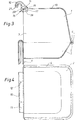
- Fig. 3 einen Längsschnitt des Badehauses gemäß Fig. 1 und 2,
- Fig. 4 eine Draufsicht auf den Wannenteil gemäß Fig. 2,
- Fig. einen Längsschnitt des Dachteiles gemäß Fig. 1,
- Fig. 6 eine Draufsicht auf das Badehaus gemäß Fig. 1 und 2 und
- Fig. 7 eine Draufsicht auf ein Vogel-Badehaus, das etwas anders als gemäß Fig. 1 und 2 ausgebildet ist.
- Das Vogel-Badehaus gemäß Zeichnung besteht aus zwei voneinander unabhängigen Teilen aus Kunststoff, nämlich einem Dachteil 1 und einem Wannenteil 2. Es ist in einem waagerechten Querschnitt in etwa rechteckig. Der Wannenteil 2 ist rundum gleichmäßig von gleichhohen Wandungen abgeschlossen und eine Durchlaß-Öffnung 3 ist vollständig im Dachteil vorgesehen und bildet dessen Vorderseite. Die Rückseiten des Dachteiles und des Wannenteiles sind gegenüber einer Senkrechten leicht schräg gegenläufig geneigt, so daß der waagerechte Querschnitt des Badehauses im Bereich der Stoßstelle von Dach- und Wannenteil am größten ist.
- Der Wannenteil 2 weist an seinem oberen Rand entlang den beiden Längsseiten und der Rückseite durchgehend einen um 90° gegenüber der Wandung des Wannenteiles nach außen abgewinkelten Führungssteg 4 auf. Der Dachteil 1 weist entlang seinem unteren Rand an beiden Längsseiten und an der Rückseite durchgehend eine um 90° gegenüber der Wandung des Dachteiles nach außen abgewinkelte Nutrinne 5 auf, die eine Führungsnut 6 bildet, in welche gemäß Fig. 3 und 6 der Führungssteg 4 eingeschoben ist. Der Führungssteg 4 füllt die Führungsnut 6 der Tiefe nach völlig aus, so daß Dachteil und Wannenteil nicht gegeneinander wackeln können.
- Ganz kurz vor dem vorderen Ende der beiden seitlichen Bereiche des Führungssteges 4 ist in jedem der seitlichen Bereiche eine Rastausnehmung 8 vorgesehen, deren Tiefe maximal der halben Tiefe bzw. Breite des Steges entspricht. In der unteren Wandung der Führungsnut 6 ist nahe jedem der beiden vorderen Enden eine Rastausnehmung 8 vorgesehen, wie Fig. 1 und 6 erkennen lassen. Die relativ flache bzw. niedrige Rastnase läßt sich, unter elastischer Biegung der Seitenwandungen des Dachteiles 1 und der Wandungen der Führungsnut, wegen der Abrundung relativ leicht wieder aus der Rastausnehmung herausziehen.
- An der Vorderseite des Wannenteiles 2 sind zwei breite, laschenartige Haken 10 mit Abstand voneinander vorgesehen, die oben zum Biegungsbereich 11 hin ineinander übergehen. Der Biegungsbereich 11 ist an der Oberseite geriffelt, um den Vögeln bei Start und Landung sicheren Halt zu geben. Die beiden Haken 10 ragen über den Boden des Wannenteiles 2 beachtlich nach unten hinaus. Parallel zu dem hinausragenden Teil der Haken, der etwa ein Viertel der Gesamtlänge des Hakens ausmacht, ragt eine Ab stützleiste 7 quer über die Breite der Vorderseite des Wannenteiles nach unten. An der Innenseite beider Haken 10 ist jeweils mittig ein vorragender Sims 12 vorgesehen.
- Der Dachteil 1 besitzt oben eine Decke 13, die durchgehend gleich dick ist, also auch über einen vorderen Randstreifen 14 hin gleich dick ist. Auf diesen Randstreifen 14 sind mit Abstand voneinander zwei Haken 15, die jeweils aus einem Hakenglied 16 und einem Fuß 17 bestehen, aufgeschoben. Der Fuß 17 ist in etwa rechteckig und besitzt an der oberen Fläche eine in Einschubrichtung verlaufende mittige Verstärkungsrippe 18.
- Der Fuß 17 ist über den größten Teil seiner rechtwinkelig zum Randstreifen 14 verlaufenden Abmessung in waagerechter Ebene mittig von einem Klemmschlitz 19 geteilt, in den der Randstreifen 14 eingeklemmt ist und dessen Breite bei abgezogenem Fuß geringer als die Dicke des Randstreifens ist. Der Klemmschlitz 19 endet in einer abgerundeten Verbreiterung 20, die parallel zur vorderen Kante der Decke 13 verläuft. Die den Klemmschlitz 17 begrenzenden beiden Schenkelteile, die gegeneinander elastisch biegsam sind, bilden jeweils ballige bzw. abgerundere Klemmflächen, die an dem Randstreifen 14 anliegen.
- Der Fuß 17 trägt an der Oberseite das Hakenglied 16, das in Richtung der vorderen Decken-Kante schmäler ist als der Fuß und sich rechtwinkelig zur vorderen Decke-Kante etwa über den ganzen Fuß erstreckt. Die rechtwinkelig zur Dekke-Kante verlaufende Abmessung des Hakengliedes 16 verjüngt sich vom Fuß weg zur Mitte des Hakengliedes hin. Das Hakenglied 16 weist an beiden Seiten je eine Höhlung 21 auf, die sich fast über die gesamte Länge des Hakengliedes erstreckt.
- Der gesamte Haken besteht aus einem steif elastischen Kunststoff hoher Festigkeit, z. B. einem schlag- oder hochschlagfesten Polystyrol. Das Badehaus ist frei von Zusatzeinrichtungen, elektrischen Einrichtungen, Pumpen oder sonstigen Ergänzungen und damit sehr leicht.
- Bei der Ausführungsform gemäß Fig. 7 ist die Rastausnehmung 8 im Führungssteg 4 und die Rastnase 9 am Grund der Führungsnut 6 vorgesehen. Rastnase 9 und Rastausnehmung 8 sind jeweils teilkreisförmig abgerundet.
Claims (16)
Priority Applications (1)
| Application Number | Priority Date | Filing Date | Title |
|---|---|---|---|
| AT82103594T ATE12020T1 (de) | 1981-06-03 | 1982-04-28 | Vogel-badehaus. |
Applications Claiming Priority (4)
| Application Number | Priority Date | Filing Date | Title |
|---|---|---|---|
| DE19818116459 DE8116459U1 (de) | 1981-06-03 | 1981-06-03 | "vogel-badehaus" |
| DE8116459U | 1981-06-03 | ||
| DE8206785U | 1982-03-11 | ||
| DE19828206785 DE8206785U1 (de) | 1982-03-11 | 1982-03-11 | Vogel-badehaus |
Publications (2)
| Publication Number | Publication Date |
|---|---|
| EP0066093A1 EP0066093A1 (de) | 1982-12-08 |
| EP0066093B1 true EP0066093B1 (de) | 1985-03-06 |
Family
ID=25948971
Family Applications (1)
| Application Number | Title | Priority Date | Filing Date |
|---|---|---|---|
| EP82103594A Expired EP0066093B1 (de) | 1981-06-03 | 1982-04-28 | Vogel-Badehaus |
Country Status (5)
| Country | Link |
|---|---|
| US (1) | US4432303A (de) |
| EP (1) | EP0066093B1 (de) |
| DE (1) | DE3262487D1 (de) |
| DK (1) | DK200482A (de) |
| HK (1) | HK47287A (de) |
Families Citing this family (5)
| Publication number | Priority date | Publication date | Assignee | Title |
|---|---|---|---|---|
| US5195457A (en) * | 1992-08-17 | 1993-03-23 | Namanny Bradley L | Pet enclosure |
| US5471950A (en) * | 1993-10-25 | 1995-12-05 | White; Elizabeth S. | Animal carrier with detachable litter box |
| US6408795B1 (en) | 2001-03-27 | 2002-06-25 | John Goodger | Decorative avian anti-splatter wall panel |
| US8261695B2 (en) * | 2010-01-21 | 2012-09-11 | John Barton Huber | Birdbath with integrated automated maintenance |
| US10099738B2 (en) * | 2013-12-05 | 2018-10-16 | Jurgen K. Beneke | Rack for a bicycle having a seat |
Family Cites Families (4)
| Publication number | Priority date | Publication date | Assignee | Title |
|---|---|---|---|---|
| US1455105A (en) * | 1922-05-18 | 1923-05-15 | William M Harmon | Knockdown chicken coop |
| GB723071A (en) * | 1952-10-22 | 1955-02-02 | Ernest George Hale | Combination nursery birdcage and bird bath |
| GB774557A (en) * | 1954-12-28 | 1957-05-08 | Hygienic Wire Works Ltd | Improvements in or relating to bird baths and like receptacles for attachment to bird cages |
| DE1927859U (de) * | 1965-09-30 | 1965-11-25 | Ernst Heuser | Badehaus fuer voegel vorzugsweise zum anbau an kaefige. |
-
1982
- 1982-04-28 DE DE8282103594T patent/DE3262487D1/de not_active Expired
- 1982-04-28 EP EP82103594A patent/EP0066093B1/de not_active Expired
- 1982-05-05 DK DK200482A patent/DK200482A/da not_active Application Discontinuation
- 1982-05-26 US US06/382,237 patent/US4432303A/en not_active Expired - Fee Related
-
1987
- 1987-06-18 HK HK472/87A patent/HK47287A/xx unknown
Also Published As
| Publication number | Publication date |
|---|---|
| DE3262487D1 (en) | 1985-04-11 |
| EP0066093A1 (de) | 1982-12-08 |
| HK47287A (en) | 1987-06-26 |
| DK200482A (da) | 1982-12-04 |
| US4432303A (en) | 1984-02-21 |
Similar Documents
| Publication | Publication Date | Title |
|---|---|---|
| DE3346384C2 (de) | Wischarm, insbesondere für Wischanlagen an Kraftfahrzeugen | |
| DE4023284A1 (de) | Einstueckiger zuggriff mit einrastwirkung | |
| DE10018864A1 (de) | Halterung für die Tür einer Duschkabine | |
| DE19617269A1 (de) | Mehrteilige Fassadenklammer | |
| DE3107903C2 (de) | Selbsttätig sperrender Schieber für Reißverschlüsse | |
| DE937859T1 (de) | Automatische Arretierung für Rolläden | |
| DE4032473C3 (de) | Haltevorrichtung für Rohre und eine Abdeckprofilleiste | |
| EP0066093B1 (de) | Vogel-Badehaus | |
| AT394080B (de) | Einstecktopf fuer ein viergelenk-moebelscharnier | |
| DE8412965U1 (de) | Tuer fuer den back- und bratraum eines bratofens | |
| DE69803455T2 (de) | Dichtung aus Elastomer für Backofen | |
| DE2003366A1 (de) | Vorhangaufhaengevorrichtung und dazu dienende Schiene und kombinierte Gleithaken | |
| DE3804176A1 (de) | Tuerverschluss fuer hausgeraete o. dgl. | |
| DE69934286T2 (de) | Rahmengestell, insbesondere für ein Elektrogerät | |
| DE4401128C2 (de) | Wandkonsole für die Montage und Demontage eines Heizkörpers | |
| DE2721541C3 (de) | Rasterdecke | |
| DE2854176C2 (de) | Kleidungs- und Wäschehalter für eine Duschtrennwand | |
| DE2607129C3 (de) | Leuchte mit einem federnden Einrastverschluß | |
| DE8116459U1 (de) | "vogel-badehaus" | |
| DE8206785U1 (de) | Vogel-badehaus | |
| DE20113468U1 (de) | Gehäuse für ein Kältegerät | |
| DE2405388C3 (de) | Querprofilschelle für Unterdecken | |
| DE4445415A1 (de) | Verbindungsstück zum schwenkbaren Verbinden eines Wischblattes mit einem Wischarm eines Kraftfahrzeugscheibenwischers | |
| DE7025049U (de) | Verbindungsorgane zur befestigung eines blendrahmens an einer mauerzange. | |
| DE3107339C2 (de) | Verbindung eines Leuchtenrahmens mit einer darin schwenkbar gelagerten, lichtdurchlässigen Abdeckung |
Legal Events
| Date | Code | Title | Description |
|---|---|---|---|
| PUAI | Public reference made under article 153(3) epc to a published international application that has entered the european phase |
Free format text: ORIGINAL CODE: 0009012 |
|
| AK | Designated contracting states |
Designated state(s): AT BE CH DE FR GB IT LI NL SE |
|
| 17P | Request for examination filed |
Effective date: 19830408 |
|
| RBV | Designated contracting states (corrected) |
Designated state(s): AT BE CH DE FR GB IT LI NL SE |
|
| GRAA | (expected) grant |
Free format text: ORIGINAL CODE: 0009210 |
|
| AK | Designated contracting states |
Designated state(s): AT BE CH DE FR GB IT LI NL SE |
|
| PG25 | Lapsed in a contracting state [announced via postgrant information from national office to epo] |
Ref country code: SE Effective date: 19850306 Ref country code: NL Effective date: 19850306 Ref country code: IT Free format text: LAPSE BECAUSE OF FAILURE TO SUBMIT A TRANSLATION OF THE DESCRIPTION OR TO PAY THE FEE WITHIN THE PRESCRIBED TIME-LIMIT;WARNING: LAPSES OF ITALIAN PATENTS WITH EFFECTIVE DATE BEFORE 2007 MAY HAVE OCCURRED AT ANY TIME BEFORE 2007. THE CORRECT EFFECTIVE DATE MAY BE DIFFERENT FROM THE ONE RECORDED. Effective date: 19850306 Ref country code: FR Free format text: THE PATENT HAS BEEN ANNULLED BY A DECISION OF A NATIONAL AUTHORITY Effective date: 19850306 Ref country code: BE Effective date: 19850306 |
|
| REF | Corresponds to: |
Ref document number: 12020 Country of ref document: AT Date of ref document: 19850315 Kind code of ref document: T |
|
| REF | Corresponds to: |
Ref document number: 3262487 Country of ref document: DE Date of ref document: 19850411 |
|
| PGFP | Annual fee paid to national office [announced via postgrant information from national office to epo] |
Ref country code: AT Payment date: 19850418 Year of fee payment: 4 |
|
| NLV1 | Nl: lapsed or annulled due to failure to fulfill the requirements of art. 29p and 29m of the patents act | ||
| EN | Fr: translation not filed | ||
| PLBE | No opposition filed within time limit |
Free format text: ORIGINAL CODE: 0009261 |
|
| STAA | Information on the status of an ep patent application or granted ep patent |
Free format text: STATUS: NO OPPOSITION FILED WITHIN TIME LIMIT |
|
| 26N | No opposition filed | ||
| PG25 | Lapsed in a contracting state [announced via postgrant information from national office to epo] |
Ref country code: AT Effective date: 19860428 |
|
| PG25 | Lapsed in a contracting state [announced via postgrant information from national office to epo] |
Ref country code: LI Effective date: 19870430 Ref country code: CH Effective date: 19870430 |
|
| REG | Reference to a national code |
Ref country code: CH Ref legal event code: PL |
|
| PG25 | Lapsed in a contracting state [announced via postgrant information from national office to epo] |
Ref country code: GB Effective date: 19880428 |
|
| GBPC | Gb: european patent ceased through non-payment of renewal fee | ||
| PG25 | Lapsed in a contracting state [announced via postgrant information from national office to epo] |
Ref country code: DE Effective date: 19890103 |