EP0066190A2 - Steuerkreissystem für Fahrzeuge - Google Patents
Steuerkreissystem für Fahrzeuge Download PDFInfo
- Publication number
- EP0066190A2 EP0066190A2 EP82104373A EP82104373A EP0066190A2 EP 0066190 A2 EP0066190 A2 EP 0066190A2 EP 82104373 A EP82104373 A EP 82104373A EP 82104373 A EP82104373 A EP 82104373A EP 0066190 A2 EP0066190 A2 EP 0066190A2
- Authority
- EP
- European Patent Office
- Prior art keywords
- control circuit
- switch
- turned
- switches
- terminal
- Prior art date
- Legal status (The legal status is an assumption and is not a legal conclusion. Google has not performed a legal analysis and makes no representation as to the accuracy of the status listed.)
- Granted
Links
Images



Classifications
-
- B—PERFORMING OPERATIONS; TRANSPORTING
- B60—VEHICLES IN GENERAL
- B60R—VEHICLES, VEHICLE FITTINGS, OR VEHICLE PARTS, NOT OTHERWISE PROVIDED FOR
- B60R16/00—Electric or fluid circuits specially adapted for vehicles and not otherwise provided for; Arrangement of elements of electric or fluid circuits specially adapted for vehicles and not otherwise provided for
- B60R16/02—Electric or fluid circuits specially adapted for vehicles and not otherwise provided for; Arrangement of elements of electric or fluid circuits specially adapted for vehicles and not otherwise provided for electric constitutive elements
- B60R16/023—Electric or fluid circuits specially adapted for vehicles and not otherwise provided for; Arrangement of elements of electric or fluid circuits specially adapted for vehicles and not otherwise provided for electric constitutive elements for transmission of signals between vehicle parts or subsystems
- B60R16/027—Electric or fluid circuits specially adapted for vehicles and not otherwise provided for; Arrangement of elements of electric or fluid circuits specially adapted for vehicles and not otherwise provided for electric constitutive elements for transmission of signals between vehicle parts or subsystems between relatively movable parts of the vehicle, e.g. between steering wheel and column
Definitions
- the present invention relates to a control circuit system for automobiles including a plurality of switches such as a horn switch provided on the steering handle.
- the present invention has been made in view of the above-mentioned disadvantage, and an object thereof is to provide a control circuit system comprising a plurality of command switches including a horn switch mounted on the steering handle, a control circuit for generating a control signal in response to a command signal from the command switches, a normally-closed relay switch interposed between the command switches and the electric horn and controlled by an output signal of the control circuit, and a signal coupler circuit for connecting the command switches and the control circuit by a single common line.
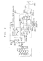
- reference numeral 1 designates a battery mounted on an automobile, and numeral 2 electric horn with an end thereof connected to the positive terminal of the battery 1 and the other end thereof connected to the end B of a normally-closed contact of a relay 3.
- the horn 2 includes therein a normally-open control relay and sounds in response to the energization of the . control relay.
- the normally-closed relay 3 thus controls the drive current of the control relay for the horn 2.
- the drive coil of the relay 3 having a normally-closed contact has an end thereof connected to the positive terminal of the battery 1, and the other end thereof connected to the terminal 7c of a control circuit 7.
- the other end S of the normally-closed contact is connected to the terminal 7b of the control circuit 7 and the contact 4 thereby to form a signal line.
- the contact 4 is of lever type fixed on the side of the body and in contact with the steering handle, the leading end of the contact 3 being in contact with a slip ring 5 which is also kept in electrical contact by the rotation of the handle. Further, the slip ring 5 is connected to the signal line 6a of switches 6 including switches Sl, S2, S3 and S4, with an end of each thereof grounded.
- the other end of the switch Sl is connected to an end of the resistor Rl; the other end of the switch S2 is connected to the other end of the resistor Rl and an end of the resistor R2; the other end of the switch S3 is connected to the other end of the resistor R2 and an end of the resistor R3; and the other end of the switch S4 is connected to the other end of the resistor R3 and through the terminal 6a to the slip ring 5.
- the switch S5 makes up a power switch for the control circuit 7 and a load 8.
- the control circuit 7 includes integrated circuits IC1 to IC14, resistors R4 to R13, capacitors Cl to C3, transistors Tl to T4 and a diode Dl.
- the terminal 7a is connected through the power switch S5 to the positive terminal of the battery 1.
- the terminal 7d is grounded while the terminals 7e, 7f and 7d are connected to the terminals 8b, 8c and 8d of the load respectively.
- the semiconductor integrated circuit ICl makes up what is called a three-terminal series regulator which generates a stabilized voltage (5V) by applying a voltage (12V) between a common terminal GND and an input terminal IN.
- the integrated circuits IC2, IC3, IC4 and IC5 are generally-known voltage comparators.
- the power terminals of the integrated circuits IC2 to IC5 are connected to the power line V and the grounding terminals thereof to the grounding line E.
- the integrated circuits IC6, IC7, IC8, IC9, IC10, IC11 and IC12 are logic elements; IC6 is three-input NOR circuit; IC7 a two-input NOR circuit; IC8 and IC9 are inverters; and IC10, IC11, IC12 are AND elements.
- the power terminals of the integrated circuits IC6 to IC12 are connected to the power line V and the grounding terminals thereof connected to the grounding line E.
- the power input terminal 7a of the control circuit 7 is connected to the input IN of the regulator IC1, and the output OUT supplies power to the power line V.
- the signal input terminal 7b is connected to the cathode of the diode Dl.
- the anode of the diode Dl is connected to an end of the resistor R4 and each one input of the voltage comparators IC2 to IC4.
- the other end of the resistor R4 is connected to the power line V.
- the resistors R5 to R9 are connected to each other to divide the potential of the power line V and the grounding lines.
- the contact between the resistors R5 and R6 is connected to the positive terminal of the voltage comparator IC2; the contact between the resistors R6 and R7 is connected to the positive terminal of the voltage comparator IC3; the contact between the resistors R7 and R8 is connected to the positive terminal of the voltage comparator IC4; and the contact between the resistors R8 and R9 is connected to the positive terminal of the voltage comparator IC5.
- the output of the voltage comparator IC2 is connected to the input terminal of the logic circuit IC10.
- the output terminal of the voltage comparator IC10 is connected to an end of the resistor R10, and the other end thereof is connected to the base of the transistor Tl and an end of the capacitor Cl.
- the other end of the capacitor Cl and the emitter of the transistor Tl are connected to a grounding line.
- the collector of the transistor Tl is connected through the output terminal 7e to the load 8b.
- the output of the voltage comparator IC3 is connected to the input of the logic circuits IC6 and IC11.
- the output of the logic circuit IC11 is connected to an end of the resistor Rll, and the other end of the resistor Rll is connected to the base of the transistor T2 and an end of the capacitor C2.
- the other end of the capacitor C2 and the emitter of the transistor T2 are grounded.
- the collector of the transistor T2 is connected through the terminal 7f to the load 8c.
- the output of the voltage comparator IC4 is connected to the input of the logic circuits IC6, IC7 and IC12, and the output of the logic circuit IC12 is connected to an end of the resistor R12.
- the other end of the resistor R12 is connected to the base of the transistor T3 and an end of the capacitor C3.
- the other end of the capacitor C3 and the emitter of the transistor T3 are connected to the grounding line E.
- the collector of the transistor T3 is connected through the terminal 7g to the terminal of the load 8d.
- the output terminal of the voltage comparator IC5 is connected with the inputs of the logic circuits I C6, IC7, IC8 and IC9, and the output of the logic circuit IC9 is connected to an end of the resistor R13.
- the other end of the resistor R13 is connected to the base of the transistor T4, the emitter of which is connected to the grounding line E.
- the collector of the transistor T4 is connected through the terminal 7c to an end of. the coil terminal of the relay 3 having a normally-closed contact.
- the output terminal of the logic circuit IC6 is connected to the input terminal of the logic circuit IC10.
- the output terminal of the logic circuit IC7 is connected to the input terminal of the logic circuit IC11.
- the output terminal of the logic circuit IC8 is connected to the input terminal of the logic circuit IC12.
- the values of the resistors Rl to R9 are determined in such a manner that the potential of the terminal 7h is 7j ⁇ 7h ⁇ 7i when the switch Sl is depressed, 7k ⁇ 7h ⁇ 7j when the switch S2 is depressed, 71 ⁇ 7h ⁇ 7k when the switch S3 is depressed, and 7h ⁇ 71 when the switch S4 is depressed. Also, the impedance of the resistors Rl to R3 are determined sufficiently high as compared with the impedance of the horn 2.
- the resistance value of the resistors Rl to R3 is high as compared with that of the horn 2 as mentioned above, and therefore the horn 2 is not actuated.
- the switch S4 is turned on, by contrast, the horn 2 is actuated through the relay 3, the contact 4, the slip ring 5 and the switch S4. In this way, when the power supply of the control circuit is cut off, the switch S4 is operated normally as a horn switch, and the horn 2 is not erroneously actuated by other switches.
- the switch S5 is turned on, that is, the power supply for the control circuit is turned on. If the switches Sl to S4 are all turned off, the signal input line 7b is substantially at the same potential as the battery voltage, and therefore the anode potential of the diode Dl is reduced to the same level as the power line V by the resistor R4, so that the outputs of all the voltage comparators IC2 to IC5 are at low level. Since the logic circuits IC10, IC11, IC12 are at low level, the transistors Tl, T2, T3 are turned off respectively.
- the "0" level is reversed by the logic circuit IC9 and therefore current is supplied to the base of the transistor T2 through the resistor R13, so that the transistor T4 is turned on, the relay 3 is driven and the horn 2 is separated from the signal line. Since the potential of the terminal 7h remains unchanged, however, the horn 2 is kept separated from the signal line.
- the potential of the terminal 7h is placed between those of the terminal 7k and the terminal 7j, so that the outputs of the voltage comparators IC2 and IC3 are raised to high level and the outputs of the voltage comparators IC4 and IC5 are reduced to low level.
- one of the input terminals of the logic circuit IC6 is at high level, and therefore the output terminal of the logic circuit IC6 is reduced to low level.
- the output of the logic circuit IC10 is also reduced to low level, thus keeping the transistor Tl off. Since the inputs of the logic circuit IC7 are at low level, the output thereof is at high level, so that the input terminals of the logic circuit 11 are at level.
- the output terminal of the logic circuit IC11 is also raised to high level, and the transistor T2 is turned on and applies a signal to the terminal 8c of the load 8.
- the control circuit is supplied with power, so that the transistor T2 is turned off and no signal is produced therefrom.
- an end each of the logic circuits IC10 and ICll is at low level, so that the outputs thereof are also at low level, with the result that the transistors Tl and T2 are turned off. Since the input of the logic circuit IC8 is at low level, the output thereof is at high level. The inputs of the logic circuit IC12 are at high level, and the output thereof is also at high level, so that the transistor T3 is turned on and a signal is applied to the input terminal 8d of the load 8. When the handle switch S3 is turned off, the power supply for the control circuit 7 is turned on, and thus the signal is not applied to the load 8.
- the switch Sl is an acceleration switch (the vehicle is accelerated while this switch is on, and runs at steady speed obtained at the time of turning it off)
- the switch S2 is a restoration switch (if this switch is turned on after cancelling the steady speed running, the condition before cancellation is restored)
- the switch S3 is a deceleration switch (the vehicle is decelerated while this switch is on, and runs at a seady speed obtained by turning it off). Even if two switches are operated by error, a danger is avoided withut any acceleration.
- the voltage comparators and the logic circuits are made up of semiconductor integrated circuits, which may be replaced with equal effect by diodes or the like. Also in the above-described embodiment, the input voltage of the voltage comparators is stabilized by use of regulator. This stabilization function may be eliminated within the range of variations of battery voltage.
- the four switches used in the embodiment may be increased or descreased in number.
- the resistors Rl, R2, R3 making up the switches may be replaced by diodes or the like.
- the load may take the form of a direction indicator, lamp control, or wiper control or any combination thereof.
- a control circuit is provided separate from a load circuit. This configuration may be replaced by another configuration in which the control circuit is incorporated in the load circuit or vice versa.
- the switches are mounted on the steering handle, so that the driver is capable of driving the vehicle accurately without deforming his correct driving posture or without turning his eyes away, thereby leading to an improved operability and safety.
- reference numeral 10 designates an automotive battery
- numeral 20 a horn an end of which is connected to the positive terminal of the battery 10 and the other thereof to a terminal B of the normally-closed contact of the relay 30.
- An end of the drive coil of the relay 30 having a normally-closed contact is connected to the positive terminal of the battery 10, and the other end thereof is connected to the terminal 300a of the control circuit 300.
- the other terminal S of the normally-closed contact is connected to the contact 40 and the terminal 300b of the control circuit 300 thereby to form a signal line.
- the contact 40 is of lever type fixed to the body and has a forward end in contact with the slip ring 50 which maintains electrical contact also by rotation of the handle. Further, the slip ring 50 is connected to the signal line 400a of the switches 400.
- the switches 400 include a set switch 70 for ordering the start of the fixed or steady speed running, a resume switch 80 for restoring a target speed as before the cancellation and starting the fixed speed running after cancellation of the fixed speed running, a cancellation switch 90 for cancellation of the fixed speed running and a horn switch 60, each of which has an end thereof grounded.
- the other end of the switch 90 is connected to an end of the resistor 120
- the other end of the switch 80 is connected to the other end of the resistor 120 and an end of the resistor 110.
- the other end of the switch 70 is connected to the other end of the resistor 110 and an end of the resistor 100.
- the other end of the switch 60 is connected to the other end of the resistor 100 and to the slip ring 50 via the terminal 400a.
- the switch 310 is a power switch for the control circuit 300.
- the control circuit 300 contains therein a microcomputer 140 having an analog-digital conversion function 140A, an internal timer interruption function and an external interruption function.
- the control unit 300 turns on the transistors 230 and 240 and gives a cancellation command, a control command or the like to a throttle actuator 250 through a buffer 150.
- This throttle valve actuator 250 is operatively coupled with a throttle valve 350 making up a speed regulating element and includes a control valve 250a for regulating the internal pressure and a cancellation valve 250b.
- control unit 300 is supplied with vehicle speed data from a vehicle speed detector system 260 including a rotating member 260a having four magnetic poles rotated by a meter cable corresponding to the rotation of the vehicle wheels and a reed switch 260b adapted to be closed each time of approach thereto of any of the magnetic poles, four pulse signals being produced for each revolution of the rotating member 260a or meter cable.
- a vehicle speed detector system 260 including a rotating member 260a having four magnetic poles rotated by a meter cable corresponding to the rotation of the vehicle wheels and a reed switch 260b adapted to be closed each time of approach thereto of any of the magnetic poles, four pulse signals being produced for each revolution of the rotating member 260a or meter cable.
- the meter cable makes 637 rpm.
- the switch 270 is comprised of a logic sum including a brake signal and a clutch signal for cancellation of the fixed speed running. These signals are applied to the microcomputer 140 through the buffer 150.
- Numeral 130 designates what is called a three-terminal series regulator for generating a stabilized voltage (5 V) at the output terminal OUT by applying a voltage (12 V) between the common terminal GND and the input terminal IN.
- the collector terminal of the transistor 220 is connected to an end of the coil of the normally-closed contact relay 30. The transistor 220 is normally turned on thereby to turn off the contact of the relay 30, thus separating the horn from the signal line.
- the signal from the switches 400 namely, the voltage of the input terminal 300b is determined by the resistance value of the discrimination impedance 170 and the resistance value of the switches 400.
- This input voltage signal is divided by the resistors 200 and 210 through the diode 160, connected to the analog input terminal of the microcomputer, and converted from an analog quantity to a digital quantity in the microcomputer.
- the diode 160 is for blocking the current flow into the control circuit which otherwise might be caused by the fact that when the power switch 310 is turned off, the contact of the normally-closed contact 30 is turned on so that the potential of the signal line reaches substantially the same level as the positive terminal of the battery 10.
- the resistors 200 and 210 are for dividing the input signal level into an input voltage range of the microcomputer.
- the signal voltage level is applied to the microcomputer 140, and in accordance with the digital quantity thereof, which of the switches 400 is depressed is determined.
- the power switch 310 is turned off, the transistor 220 is turned off and the contact of the relay 30 is closed, so that the horn switch 60 is turned on thereby to sound the horn.
- the horn switch 60 is turned on with the power switch 310 on, the signal level thereof is determined by the microcomputer 140 as explained above, so that the transistor 220 is turned off through the buffer 150 and the contact of the relay 30 is closed thereby to sound the horn.
- step 510 The operation after power is supplied to the control unit 300 through the main switch 310 will be described with reference to Figs. 3 and 4.
- the microcomputer 140 therein executes the initialization routine of step 510.
- the transistor 220 is turned on, the contact of the normally-closed contact relay opens and the horn is separated.
- step 520 If the set switch is operated by the switch signal data obtained by the flow shown in Fig. 4, the process is passed to the step 540, while if the set switch is not operated, the process proceeds to step 530 (Fig. 4 will be described later).
- step 550 If the resume switch is turned on in the presence of a stored vehicle speed at step 530, the process is passed to step 550; while in the opposite case, the process returns to step 520 for repeating steps 520 and 530.
- the present vehicle speed is stored as a target vehicle speed, followed by step 550 where the flag is processed for starting the control or turning on the relaease valve 230 thereby to enter the fixed speed control 560.
- a duty factor for driving the negative pressure actuator is determined by the proportionality computation based on the advance compensation from the difference between the target vehicle speed and the present vehicle speed thereby to drive the control valve 240.
- step 570 it is decided whether or not a cancellation signal is received, and in the absence of the cancellation signal, the process returns to step 560 to repeat the auto drive control, while in the presence of a cancellation signal, the process proceeds to step 580 for cancellation processing, followed by the return to step 520. If the resume operation is performed at step 530, the process is passed to step 550, where the operations similar to those mentioned above are repeated with the stored vehicle speed as a target vehicle speed.
- Signals are fetched from the switches 400 by the timer interruption routine at intervals of 5 msec.
- the routine of Fig. 4 starts.
- the register used is retreated, followed by step 620 for such timer processing as the incre- mentation of the soft timer, and the process is then passed to the next step.
- the analog signal applied is read as a digital quantity, and by averaging out the particular data and the preceding data (step 640), the present data is obtained.
- step 650 the present data is compared with the decision level C 1 , and if the present data is larger than the level C 1 , the process is passed to step 670, where it is decided that none of the switches 400 is depressed, thus storing the switch data in the microcomputer 140.
- the RAM area is cleared to proceed to step 780.
- step 680 the present data is compared with the decision level C 2 . If the present data is larger than the decision level C 2 , the process is passed to step 690, where the flag for the cancellation switch ON is set, followed by step 700, where the other switch flags are cleared to proceed to step 780.
- step 720 the resume switch on flag is set, followed by step 730 where the other switch flags are reset thereby to proceed to step 780.
- step 740 it is compared with the decision level C 4' If the present data is larger than the level C 4 , the process proceeds to step 750, where the set switch on flag is set, followed by step 760 where the other switch flags are reset thereby to proceed to step 780.
- step 770 If the data is smaller than the decision level C 4 , by contrast, the process is passed to step 770, where it is decided that the horn switch is turned on, and the transistor 220 is turned off thereby to turn on the contact of the relay 30, followed by step 790.
- step 780 the transistor 220 is turned on and the contact of the relay 30 is turned off, thereby proceeding to step 790.
- the step 790 starts the analog-digital conversion of the microcomputer 140 for reading the digital quantity of the input signal by the next timer interruption.
- the process is then passed to step 800 where the register is restored, followed by the return step at 810.
- Fig. 5 shows a partial electrical circuit diagram showing a third embodiment of the present invention.
- the relay 30 is normally closed when the transistor of the switching circuit (S) is turned off.
- This transistor like in the aforementioned embodiment, is subjected to on-off control by the computer 140 in order to sound and stop the horn 20.
- the computer 140 includes a multiplicity of parts and is lower in reliability than the conventional horn, so that the switching circuit (S) is adapted to be actuated directly through the diode (D). If required, the signal line may be eliminated for actual application.
- the signal voltage level based on the switch operation is converted from an analog quantity into a digital quantity, whereby the fixed speed control unit may be controlled.
- an analog-digital conversion element may be provided outside of the microcomputer to attain the same effect.
- the voltage level on the signal line based on the operation of a switch mounted on the steering handle is subjected to analog-digital conversion, and the particular switch is identified by the digital quantity. Even when a plurality of switches are used, therefore, a single signal line serves the purpose. Also, the averaging operation of the microcomputer eliminates a noise- deadening element.
Landscapes
- Engineering & Computer Science (AREA)
- Mechanical Engineering (AREA)
- Steering Controls (AREA)
Applications Claiming Priority (4)
| Application Number | Priority Date | Filing Date | Title |
|---|---|---|---|
| JP56077679A JPS57194132A (en) | 1981-05-22 | 1981-05-22 | Control circuit |
| JP77679/81 | 1981-05-22 | ||
| JP181591/81 | 1981-11-12 | ||
| JP56181591A JPS5881838A (ja) | 1981-11-12 | 1981-11-12 | 制御回路装置 |
Publications (3)
| Publication Number | Publication Date |
|---|---|
| EP0066190A2 true EP0066190A2 (de) | 1982-12-08 |
| EP0066190A3 EP0066190A3 (en) | 1985-04-10 |
| EP0066190B1 EP0066190B1 (de) | 1987-11-04 |
Family
ID=26418756
Family Applications (1)
| Application Number | Title | Priority Date | Filing Date |
|---|---|---|---|
| EP19820104373 Expired EP0066190B1 (de) | 1981-05-22 | 1982-05-18 | Steuerkreissystem für Fahrzeuge |
Country Status (3)
| Country | Link |
|---|---|
| US (1) | US4532432A (de) |
| EP (1) | EP0066190B1 (de) |
| DE (1) | DE3277576D1 (de) |
Cited By (3)
| Publication number | Priority date | Publication date | Assignee | Title |
|---|---|---|---|---|
| EP0115962A3 (en) * | 1983-02-04 | 1985-03-20 | Nippondenso Co., Ltd. | Impedance discriminator responsive to operation of switches mounted on a steering wheel |
| EP0239975A3 (en) * | 1986-04-02 | 1989-04-26 | Izumi Corporation Industries, Inc. | Multiple switch control system |
| EP0729866A1 (de) * | 1995-02-28 | 1996-09-04 | Robert Bosch Gmbh | Elektronische Einrichtung |
Families Citing this family (12)
| Publication number | Priority date | Publication date | Assignee | Title |
|---|---|---|---|---|
| US4661718A (en) * | 1984-06-07 | 1987-04-28 | Nippondenso Co., Ltd. | Information and electrical power transmission system and method for vehicle |
| JPS6144034A (ja) * | 1984-08-07 | 1986-03-03 | Omron Tateisi Electronics Co | 車両のスイツチ制御装置 |
| US4578591A (en) * | 1984-10-25 | 1986-03-25 | United Technologies Automotive, Inc. | Control circuit for automotive accessory system |
| FR2580240B1 (fr) * | 1985-04-10 | 1987-07-10 | Citroen Maxime | Dispositif de regroupement constituant un clavier de contacteurs de commande d'equipements installes dans un vehicule automobile |
| US4785194A (en) * | 1986-04-02 | 1988-11-15 | Izumi Corporation Industries, Inc. | Multiple switch control system |
| JPH0162143U (de) * | 1987-04-30 | 1989-04-20 | ||
| EP0715312B1 (de) * | 1994-11-30 | 2002-10-23 | STMicroelectronics S.r.l. | Monolithischer integrierter Generator von verschiedenen Speisespannungswerten |
| US5764010A (en) * | 1995-04-28 | 1998-06-09 | United Technologies Automotive, Inc. | Control system for an automotive vehicle multi-functional apparatus |
| US6242821B1 (en) | 1999-06-07 | 2001-06-05 | Visteon Global Technologies, Inc. | CMOS passive input circuit |
| RU2162801C1 (ru) * | 1999-06-16 | 2001-02-10 | Открытое акционерное общество "Специальное конструкторское бюро приборостроения и автоматики" | Устройство для управления электродвигателем стеклоочистителя |
| US7265699B1 (en) | 2006-02-28 | 2007-09-04 | Gm Global Technology Operations, Inc. | Nine-position resistor ladder switch assembly |
| US9318281B2 (en) * | 2012-01-27 | 2016-04-19 | Steering Solutions Ip Holding Corporation | Steering wheel assembly with user controls |
Family Cites Families (10)
| Publication number | Priority date | Publication date | Assignee | Title |
|---|---|---|---|---|
| US3599052A (en) * | 1969-06-16 | 1971-08-10 | Bendix Corp | Automobile speed control |
| US3739185A (en) * | 1970-07-02 | 1973-06-12 | Tokai Rika Co Ltd | Circuit system for switches of an automobile |
| JPS604639B2 (ja) * | 1974-11-26 | 1985-02-05 | 株式会社日本自動車部品総合研究所 | 電気配線装置 |
| JPS5913004B2 (ja) * | 1975-09-29 | 1984-03-27 | 富士写真フイルム株式会社 | 電磁シヤツタ− |
| IT1164676B (it) * | 1979-04-30 | 1987-04-15 | Venturini Giancarlo | Dispositivo di comando a distanza per la manovra degli organi apparecchi e dispositivi accessori meccanici elettrici e elettromeccanici in stallati negli autoveicoli |
| DE2944224A1 (de) * | 1979-11-02 | 1981-05-07 | Robert Bosch Gmbh, 7000 Stuttgart | Steueranordnung fuer eine wischanlage fuer kraftfahrzeugscheiben |
| US4340824A (en) * | 1980-02-11 | 1982-07-20 | Motorola, Inc. | Auxiliary steering wheel command system |
| GB2074313B (en) * | 1980-03-25 | 1984-08-30 | Nissan Motor | Optical signal transmission systems |
| US4386279A (en) * | 1980-04-02 | 1983-05-31 | Nippon Soken, Inc. | Switch apparatus for vehicle |
| US4453088A (en) * | 1982-12-10 | 1984-06-05 | General Motors Corporation | Multiplex system for steering wheel mounted switches |
-
1982
- 1982-05-18 EP EP19820104373 patent/EP0066190B1/de not_active Expired
- 1982-05-18 DE DE8282104373T patent/DE3277576D1/de not_active Expired
- 1982-05-20 US US06/380,252 patent/US4532432A/en not_active Expired - Lifetime
Cited By (4)
| Publication number | Priority date | Publication date | Assignee | Title |
|---|---|---|---|---|
| EP0115962A3 (en) * | 1983-02-04 | 1985-03-20 | Nippondenso Co., Ltd. | Impedance discriminator responsive to operation of switches mounted on a steering wheel |
| US4658150A (en) * | 1983-02-04 | 1987-04-14 | Nippondenso Co., Ltd. | Impedance discriminator responsive to operation of switches mounted on a steering wheel |
| EP0239975A3 (en) * | 1986-04-02 | 1989-04-26 | Izumi Corporation Industries, Inc. | Multiple switch control system |
| EP0729866A1 (de) * | 1995-02-28 | 1996-09-04 | Robert Bosch Gmbh | Elektronische Einrichtung |
Also Published As
| Publication number | Publication date |
|---|---|
| US4532432A (en) | 1985-07-30 |
| EP0066190A3 (en) | 1985-04-10 |
| EP0066190B1 (de) | 1987-11-04 |
| DE3277576D1 (en) | 1987-12-10 |
Similar Documents
| Publication | Publication Date | Title |
|---|---|---|
| EP0066190B1 (de) | Steuerkreissystem für Fahrzeuge | |
| US4807135A (en) | Power supply control device for automotive electronic control system | |
| US4117903A (en) | Vehicle speed control system | |
| US5316868A (en) | Dual battery switch circuit | |
| EP0526985B1 (de) | Anlassersverriegelung für elektronisch gesteuertes Fahrzeug | |
| EP0376969B1 (de) | Überwachungsvorrichtung für den positionsregler eines elektronischen gaspedals | |
| US4860210A (en) | Method of determining and using a filtered speed error in an integrated acceleration based electronic speed control system for vehicles | |
| US4890231A (en) | Method of disabling a resume switch in an electronic speed control system for vehicles | |
| US4849892A (en) | Method of determining and using an acceleration correction in an integrated acceleration based electronic speed control system for vehicles | |
| US5552985A (en) | Cruising control apparatus | |
| US4896267A (en) | Electronic speed control system for vehicles, a method of determining the condition of a manual transmission clutch and of a park/neutral gear in an automatic transmission | |
| JPH0576727B2 (de) | ||
| US4467762A (en) | Control apparatus for a fuel metering system | |
| US5848366A (en) | Load driving control system for vehicle equipped with microcomputer | |
| JPS636387B2 (de) | ||
| US5085287A (en) | Cruise control apparatus for a vehicle | |
| JPS61271131A (ja) | 自動車用定速走行装置のハ−ドキヤンセル回路 | |
| US5025379A (en) | System and method for automatically controlling vehicle speed to desired cruise speed using microcomputer | |
| GB2285143A (en) | Electric vehicle brake control | |
| US4961475A (en) | Cruise control system | |
| JP2578134B2 (ja) | ソレノイドの駆動回路 | |
| EP0415452B1 (de) | Systemstruktur zur automatischen Steuerung einer Fahrzeuggeschwindigkeit auf die gewünschte Reisegeschwindigkeit | |
| US4905154A (en) | Method for compensating for cable length in a vehicle electronic speed control system | |
| JPH0455232Y2 (de) | ||
| US5742230A (en) | Apparatus for triggering a warning device |
Legal Events
| Date | Code | Title | Description |
|---|---|---|---|
| PUAI | Public reference made under article 153(3) epc to a published international application that has entered the european phase |
Free format text: ORIGINAL CODE: 0009012 |
|
| AK | Designated contracting states |
Designated state(s): DE FR GB |
|
| PUAL | Search report despatched |
Free format text: ORIGINAL CODE: 0009013 |
|
| AK | Designated contracting states |
Designated state(s): DE FR GB |
|
| 17P | Request for examination filed |
Effective date: 19850711 |
|
| GRAA | (expected) grant |
Free format text: ORIGINAL CODE: 0009210 |
|
| AK | Designated contracting states |
Kind code of ref document: B1 Designated state(s): DE FR GB |
|
| REF | Corresponds to: |
Ref document number: 3277576 Country of ref document: DE Date of ref document: 19871210 |
|
| ET | Fr: translation filed | ||
| PLBE | No opposition filed within time limit |
Free format text: ORIGINAL CODE: 0009261 |
|
| STAA | Information on the status of an ep patent application or granted ep patent |
Free format text: STATUS: NO OPPOSITION FILED WITHIN TIME LIMIT |
|
| 26N | No opposition filed | ||
| REG | Reference to a national code |
Ref country code: GB Ref legal event code: 746 |
|
| REG | Reference to a national code |
Ref country code: FR Ref legal event code: DL |
|
| PGFP | Annual fee paid to national office [announced via postgrant information from national office to epo] |
Ref country code: DE Payment date: 20010514 Year of fee payment: 20 |
|
| PGFP | Annual fee paid to national office [announced via postgrant information from national office to epo] |
Ref country code: GB Payment date: 20010516 Year of fee payment: 20 |
|
| PGFP | Annual fee paid to national office [announced via postgrant information from national office to epo] |
Ref country code: FR Payment date: 20010518 Year of fee payment: 20 |
|
| REG | Reference to a national code |
Ref country code: GB Ref legal event code: IF02 |
|
| PG25 | Lapsed in a contracting state [announced via postgrant information from national office to epo] |
Ref country code: GB Free format text: LAPSE BECAUSE OF EXPIRATION OF PROTECTION Effective date: 20020517 |
|
| REG | Reference to a national code |
Ref country code: GB Ref legal event code: PE20 Effective date: 20020517 |