EP0066268A2 - Appareil pour l'arrosage de surfaces rectangulaires - Google Patents
Appareil pour l'arrosage de surfaces rectangulaires Download PDFInfo
- Publication number
- EP0066268A2 EP0066268A2 EP82104659A EP82104659A EP0066268A2 EP 0066268 A2 EP0066268 A2 EP 0066268A2 EP 82104659 A EP82104659 A EP 82104659A EP 82104659 A EP82104659 A EP 82104659A EP 0066268 A2 EP0066268 A2 EP 0066268A2
- Authority
- EP
- European Patent Office
- Prior art keywords
- drive housing
- base
- plane
- fan nozzle
- irrigation device
- Prior art date
- Legal status (The legal status is an assumption and is not a legal conclusion. Google has not performed a legal analysis and makes no representation as to the accuracy of the status listed.)
- Granted
Links
Images

Classifications
-
- B—PERFORMING OPERATIONS; TRANSPORTING
- B05—SPRAYING OR ATOMISING IN GENERAL; APPLYING FLUENT MATERIALS TO SURFACES, IN GENERAL
- B05B—SPRAYING APPARATUS; ATOMISING APPARATUS; NOZZLES
- B05B3/00—Spraying or sprinkling apparatus with moving outlet elements or moving deflecting elements
- B05B3/02—Spraying or sprinkling apparatus with moving outlet elements or moving deflecting elements with rotating elements
- B05B3/04—Spraying or sprinkling apparatus with moving outlet elements or moving deflecting elements with rotating elements driven by the liquid or other fluent material discharged, e.g. the liquid actuating a motor before passing to the outlet
- B05B3/0417—Spraying or sprinkling apparatus with moving outlet elements or moving deflecting elements with rotating elements driven by the liquid or other fluent material discharged, e.g. the liquid actuating a motor before passing to the outlet comprising a liquid driven rotor, e.g. a turbine
- B05B3/0432—Spraying or sprinkling apparatus with moving outlet elements or moving deflecting elements with rotating elements driven by the liquid or other fluent material discharged, e.g. the liquid actuating a motor before passing to the outlet comprising a liquid driven rotor, e.g. a turbine the rotation of the outlet elements being reversible
- B05B3/0438—Tubular elements holding several outlets, e.g. apertured tubes, oscillating about an axis substantially parallel to the tubular element
Definitions
- the invention relates to a sprinkler for sprinkling square surfaces, consisting of a pedestal, a drive housing carried by the pedestal and a tubular nozzle (fan nozzle) mounted in the drive housing, with a turbine wheel driven by the inflowing irrigation water in the drive housing, the rotary movement of which is reduced by means of a reduction gear with the help a conversion gear is converted into a periodic swiveling movement of the fan nozzle, which can be swiveled back and forth about an axis parallel to the standing plane of the foot (swiveling axis), which, after completion of a half swiveling angle, has a direction of its radiation plane perpendicular to the standing surface and with reference to the direction of the radiation plane can be adjusted relative to the base of the base in such a way that the irrigated surface (irrigation, irrigation surface) is entirely or predominantly to the left or right of the plane of symmetry of the base.
- the 'radiation level' in the above sense is understood to mean the plane of the water jets which emerge from the nozzles arranged linearly on the fan nozzle at a specific instant, that is to say in a specific pivoting position.
- the radiation level achieved after completion of half a swivel angle can be achieved by a movement independent of the conversion gear and without changing the swivel angle: relative movement between the fan nozzle and the base can be displaced from the plane of symmetry.
- Such a solution also has the advantage that the respective setting of the sprinkling device can already be seen from a greater distance, which is not the case in particular for the known sprinkling devices, because the position of the sprinkling surface is not to be seen from the respective clamping position of the crank mechanism.
- the irritating labeling of the sprinkler with reference to the operating position which is particularly annoying when exporting (multilingualism), is also omitted.
- a preferred embodiment can consist in that the drive housing carrying the fan nozzle is provided with the aid of of an axle journal in the base in opposite pivoting directions is limitedly pivotable and lockable, which axle journal is arranged eccentrically to the pivot axis of the fan nozzle.
- journal 2b is arranged eccentrically to the central axis c-c of the drive housing 2 and parallel and diametrically to the pivot axis d-d.
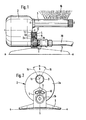
- the square sprinkler comprises a pedestal 5, a cylindrical drive housing 2 carried by the pedestal 5 and a tubular nozzle 3 (fan nozzle) mounted in the drive housing 2, which nozzle nozzle has a linear pipe section with linearly arranged nozzles or else a curved pipe section with linearly arranged nozzles ( Nozzle arch) can be formed.
- a turbine wheel (not visible in the drawing) driven by the incoming irrigation water is arranged in the drive housing, the rotational movement of which is reduced by means of a reduction gear is translated into a periodic pivoting movement of the fan nozzle 3.
- the fan nozzle can be pivoted back and forth about an axis (pivot axis) running parallel to the standing plane a-a of the standing foot 5.
- the fan nozzle 3 has a direction of its radiation plane perpendicular to the standing surface a-a after completion of a half swivel angle ⁇ .
- Pressurized water is supplied from the hose 20 to the turbine in the drive housing 2 via the connector 1.
- the cylindrical drive housing 2 is pivotally mounted via a hollow journal 2b in a bracket 4 of the pedestal 5, which is eccentric to the central axis c-c of the drive housing 2.
- the drive housing In the set pivot position, the drive housing is held only by frictional force by means of clamping screw 9, which is in threaded engagement with the housing wall 2a.
- the clamping screw can be moved without loosening while overcoming the frictional resistance in a sector cutout 10 of the console 4.
- a recess 13 is provided in the housing wall 2a in a central position according to FIG.
- the drive housing 2 is symmetrical to the base 5. The pivoting movement of the fan nozzle 3 extends to the left or right in each case over half the pivot angle ⁇
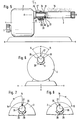
- FIG. 3 shows the drive housing 2 pivoted to the right by half the angle ⁇ .
- the fan nozzle 3 which can be pivoted about its pivot axis d-d, comes into an operating position in which the leg 14 of the angle st is transferred into the vertical position. Only the area to the right of the plane of symmetry b-b of the base 5 is irrigated.
- FIG. 4 shows how the assembly consisting of drive housing 2 and fan nozzle 3 is pivoted to the left and thus the leg 15 of the angle pc can be brought into a vertical position. In this position, the area to the left of the plane of symmetry b-b of the base 5 is irrigated.
- the pivoting of the drive housing 2 also has the advantage of a weight shift and greater stability or the advantage of the smallest foot dimensions.
- the nozzles of the fan nozzle 3 cause a reaction force N that corresponds to the direction of radiation of the water jets 16 is opposite. What is of particular interest here is the stability of the sprinkler in the extreme operating positions "left" or "right”.
- the resulting reaction force N according to FIG. 3 acts through the pivot axis dd of the fan nozzle 3 (position 17 in FIG. 3). With the lever arm L 1 it generates a torque at the foot edge 18, which is referred to below as Md 1 .
- the weight of the water supply hose 20 also has a stabilizing effect on the sprinkler. It is crucial here that it is connected and designed directly below the fan nozzle. It is also the case that the fan nozzle 3 can be brought not only into the operating positions "LEFT” - "CENTER” - “RIGHT”, but also into any position in between by pivoting the drive housing 2 with the fan nozzle 3, ie the sprinkler.
- the arrangement shown in Figures 1-4 solves the task with a minimum of technical effort and optimally stabilizes the square sprinkler. In the exemplary embodiment in FIGS. 5-8, it is not the drive housing 2 with the fan nozzle 3 as an aggregate, but only the fan nozzle 3 (or the corresponding nozzle bend) that can be pivoted into the desired operating position.
- pressure water is supplied through the rear water connection via the connection piece 1 of the turbine in the sprinkler housing 2 and a swivel tube 25 is driven via the reduction gear, which is pivotably mounted in the drive housing 2.
- the fan nozzle 3 is pivotally mounted on this swivel tube 25.
- the driver 26 is also provided with a recess 28 for the engagement of a locking ball 29 which is exposed to the pressure of the spring 30.
- the fan nozzle 3 is in the center position according to FIG.
- the swivel tube 25 has a radial recess 31 in which the cylindrical pin 32 of a screw 33 is rotatably mounted.
- the screw 33 fixed in the swivel tube 25 secures the fan nozzle 3 against the axial forces that occur and the sealing to the swivel tube 25 takes place with the 0-ring 34.
- the shoulders 35 and 36 of the fan nozzle 3 arranged in the area of the stop 27 limit the swivel path according to the preselection of the Operating position. According to FIG. 7, the fan nozzle 3 is rotated with the shoulder 36 up to the stop 27, with which the area to the left of the sprinkler is irrigated. Similarly, the shoulder 35 on the stop 27 limits the operating setting of the nozzle to the right and thus results in the irrigation of an area to the right of the sprinkler. In addition, the fan nozzle 3 can be adjusted as desired, so that any operating setting between the positions shown in FIGS. 7 and 8 is possible.
- journal 2b is eccentric to the central axis cc of the drive housing 2 and parallel and diametrical to the pivot axis dd arranged.
Landscapes
- Nozzles (AREA)
- Details Or Accessories Of Spraying Plant Or Apparatus (AREA)
- Catching Or Destruction (AREA)
Applications Claiming Priority (2)
| Application Number | Priority Date | Filing Date | Title |
|---|---|---|---|
| DE3121369 | 1981-05-29 | ||
| DE3121369A DE3121369C2 (de) | 1981-05-29 | 1981-05-29 | Beregnungsvorrichtung zur Beregnung viereckiger Flächen |
Publications (3)
| Publication Number | Publication Date |
|---|---|
| EP0066268A2 true EP0066268A2 (fr) | 1982-12-08 |
| EP0066268A3 EP0066268A3 (en) | 1983-04-06 |
| EP0066268B1 EP0066268B1 (fr) | 1986-04-02 |
Family
ID=6133492
Family Applications (1)
| Application Number | Title | Priority Date | Filing Date |
|---|---|---|---|
| EP82104659A Expired EP0066268B1 (fr) | 1981-05-29 | 1982-05-27 | Appareil pour l'arrosage de surfaces rectangulaires |
Country Status (4)
| Country | Link |
|---|---|
| US (1) | US4545532A (fr) |
| EP (1) | EP0066268B1 (fr) |
| JP (1) | JPS5830357A (fr) |
| DE (1) | DE3121369C2 (fr) |
Families Citing this family (4)
| Publication number | Priority date | Publication date | Assignee | Title |
|---|---|---|---|---|
| TWI273883B (en) * | 2005-11-30 | 2007-02-21 | Yuan Mei Corp | Automatic switching device for water entry of sprinkler |
| TWI266604B (en) * | 2005-11-30 | 2006-11-21 | Yuan Mei Corp | Splash change controlling device of sprinkler |
| EP3062604B1 (fr) * | 2013-10-29 | 2019-06-05 | Katco Holdings Pty Ltd | Base de gicleur |
| CN112452576B (zh) * | 2021-01-25 | 2021-05-18 | 常州森源科技有限公司 | 一种可调节的输料头 |
Family Cites Families (12)
| Publication number | Priority date | Publication date | Assignee | Title |
|---|---|---|---|---|
| US1942271A (en) * | 1932-01-29 | 1934-01-02 | Barrington William Frederick | Sprinkler |
| US2546241A (en) * | 1948-12-30 | 1951-03-27 | Merrill D Squiers | Oscillating lawn sprinkler |
| US2914255A (en) * | 1956-04-03 | 1959-11-24 | Sunbeam Corp | Lawn sprinkler |
| US2952413A (en) * | 1957-05-20 | 1960-09-13 | Sunbeam Corp | Lawn sprinkler |
| US2934973A (en) * | 1958-03-12 | 1960-05-03 | Atlas Press Company | Mechanical device |
| US3073532A (en) * | 1960-08-31 | 1963-01-15 | Internat Patent Res Corp | Adjsutable oscillating lawn sprinkler |
| US3047241A (en) * | 1961-08-17 | 1962-07-31 | William S Mclhinney | Adjustable spraying device |
| US3269661A (en) * | 1965-01-14 | 1966-08-30 | Seth W Thompson | Oscillatory lawn sprinkler |
| US3332624A (en) * | 1965-01-28 | 1967-07-25 | First Res Corp | Turret lawn sprinkler with oscillating mechanism |
| US3578248A (en) * | 1969-07-16 | 1971-05-11 | Western Ind Inc | Fluid sprinkler having means for driving and reversing an oscillating distributing tube of uniform speed |
| US3567122A (en) * | 1969-07-16 | 1971-03-02 | Western Ind Inc | Water sprinkler having counter means for an oscillating distributing tube of uniform speed |
| US4245786A (en) * | 1979-04-16 | 1981-01-20 | Abrahamsen Johan E | Oscillating lawn spray with variable width and length |
-
1981
- 1981-05-29 DE DE3121369A patent/DE3121369C2/de not_active Expired
-
1982
- 1982-05-26 US US06/381,948 patent/US4545532A/en not_active Expired - Fee Related
- 1982-05-27 EP EP82104659A patent/EP0066268B1/fr not_active Expired
- 1982-05-29 JP JP57090528A patent/JPS5830357A/ja active Pending
Also Published As
| Publication number | Publication date |
|---|---|
| DE3121369A1 (de) | 1982-12-30 |
| US4545532A (en) | 1985-10-08 |
| EP0066268A3 (en) | 1983-04-06 |
| EP0066268B1 (fr) | 1986-04-02 |
| JPS5830357A (ja) | 1983-02-22 |
| DE3121369C2 (de) | 1985-01-17 |
Similar Documents
| Publication | Publication Date | Title |
|---|---|---|
| DE2906648C3 (de) | Spritzdüsenanordnung für Hochdruckreinigungsgeräte | |
| DE1653870B2 (de) | Schlauchpumpe | |
| DE3530587A1 (de) | Wendestrahlrohr fuer feuerloescheinrichtungen | |
| DE2736314C3 (de) | Düse zum Versprühen eines unter Druck stehenden Mediums | |
| DE2631752A1 (de) | Schwenkende berieselungsvorrichtung | |
| EP3984436A1 (fr) | Nettoyant de surface à usage multiple | |
| EP0066268A2 (fr) | Appareil pour l'arrosage de surfaces rectangulaires | |
| DE69526052T2 (de) | Vorrichtung zur Bewegungsübertragung für den oszillierenden Arm eines Regners | |
| DE1784444C3 (de) | Strahlrohr mit schwenkbarem Mündungsteil | |
| EP3100770B1 (fr) | Melangeur pour un dispositif de lutte contre l'incendie | |
| DE2343820B2 (de) | Zeichengeraet zum perspektivischen zeichnen | |
| DE2209998B2 (de) | Sprühvorrichtung | |
| DE2256125B2 (de) | Zusammenlegbares Stativ | |
| EP3059022A1 (fr) | Appareil de nettoyage de conduites | |
| DE10134061A1 (de) | Knickgelenk für Hochdruck-Reinigungsgeräte | |
| DE2813515A1 (de) | Selektiv ueber einen teilkreis oder einen vollkreis drehbarer rieslerkopf | |
| DE4318060A1 (de) | Schwenkarmvorrichtung | |
| DE10329747B3 (de) | Schwenkkopfsystem insbesondere für Film- und Videokameras | |
| DE2414701A1 (de) | Handsteuereinrichtung zum orientieren der scheinwerfer eines fahrzeuges | |
| DE202007010271U1 (de) | Stützradanordnung für ein Fahrrad | |
| DE8116006U1 (de) | Beregnungsvorrichtung zur Beregnung viereckiger Flächen | |
| DE3114095A1 (de) | Beregungsvorrichtung mit hin- und herschwenkbarer faecherduese | |
| DE3523538C1 (de) | Spritzpistole | |
| DE2520039C3 (de) | Steuervorrichtung tür einen doppelseitig beaufschlagbaren, einenends an ein Bodenbearbeitungsgerät, anderenends an einen Schlepper anschlieBbaren Hydraulikzylinder | |
| DE164458C (fr) |
Legal Events
| Date | Code | Title | Description |
|---|---|---|---|
| PUAI | Public reference made under article 153(3) epc to a published international application that has entered the european phase |
Free format text: ORIGINAL CODE: 0009012 |
|
| AK | Designated contracting states |
Designated state(s): FR GB IT |
|
| PUAL | Search report despatched |
Free format text: ORIGINAL CODE: 0009013 |
|
| AK | Designated contracting states |
Designated state(s): FR GB IT |
|
| 17P | Request for examination filed |
Effective date: 19830901 |
|
| GRAA | (expected) grant |
Free format text: ORIGINAL CODE: 0009210 |
|
| AK | Designated contracting states |
Kind code of ref document: B1 Designated state(s): FR GB IT |
|
| ITF | It: translation for a ep patent filed | ||
| ET | Fr: translation filed | ||
| PLBE | No opposition filed within time limit |
Free format text: ORIGINAL CODE: 0009261 |
|
| STAA | Information on the status of an ep patent application or granted ep patent |
Free format text: STATUS: NO OPPOSITION FILED WITHIN TIME LIMIT |
|
| 26N | No opposition filed | ||
| PG25 | Lapsed in a contracting state [announced via postgrant information from national office to epo] |
Ref country code: FR Free format text: LAPSE BECAUSE OF NON-PAYMENT OF DUE FEES Effective date: 19880129 |
|
| REG | Reference to a national code |
Ref country code: FR Ref legal event code: ST |
|
| PG25 | Lapsed in a contracting state [announced via postgrant information from national office to epo] |
Ref country code: GB Free format text: LAPSE BECAUSE OF NON-PAYMENT OF DUE FEES Effective date: 19881121 |