EP0066312A1 - Vorrichtung zum Verlegen von Weichen und Gleisabschnitten - Google Patents
Vorrichtung zum Verlegen von Weichen und Gleisabschnitten Download PDFInfo
- Publication number
- EP0066312A1 EP0066312A1 EP82200555A EP82200555A EP0066312A1 EP 0066312 A1 EP0066312 A1 EP 0066312A1 EP 82200555 A EP82200555 A EP 82200555A EP 82200555 A EP82200555 A EP 82200555A EP 0066312 A1 EP0066312 A1 EP 0066312A1
- Authority
- EP
- European Patent Office
- Prior art keywords
- platform
- machine
- railway
- telescopic
- bar
- Prior art date
- Legal status (The legal status is an assumption and is not a legal conclusion. Google has not performed a legal analysis and makes no representation as to the accuracy of the status listed.)
- Granted
Links
- 239000011435 rock Substances 0.000 claims description 2
- 238000012423 maintenance Methods 0.000 description 2
- 238000005192 partition Methods 0.000 description 2
- 125000006850 spacer group Chemical group 0.000 description 2
- 238000012546 transfer Methods 0.000 description 2
- 230000002512 anti-withdrawal effect Effects 0.000 description 1
- 238000013461 design Methods 0.000 description 1
- 238000003780 insertion Methods 0.000 description 1
- 230000037431 insertion Effects 0.000 description 1
- 238000012986 modification Methods 0.000 description 1
- 230000004048 modification Effects 0.000 description 1
Images




Classifications
-
- E—FIXED CONSTRUCTIONS
- E01—CONSTRUCTION OF ROADS, RAILWAYS, OR BRIDGES
- E01B—PERMANENT WAY; PERMANENT-WAY TOOLS; MACHINES FOR MAKING RAILWAYS OF ALL KINDS
- E01B29/00—Laying, rebuilding, or taking-up tracks; Tools or machines therefor
- E01B29/02—Transporting, laying, removing, or renewing lengths of assembled track, assembled switches, or assembled crossings
Definitions
- This invention concerns the railway sector in an entirely general manner, and more particularly it relates to the maintenance of railway lines, i.e. to the replacement of railway switches and track portions in general.
- railway lines are known to be formed from a plurality of consecutive track portions of considerable length, along which suitable railway switches, commonly known as points, are disposed in order to connect together two or more separate pairs of rails.
- the maintenance of railway lines is also known to comprise the replacement of damaged or excessively worn track portions and switches.
- Said switches and track portions are replaced by withdrawing the complete element to be replaced, and installing a corresponding new element.
- a first drawback of said known machines is that they are hardly suitable for handling elements of different configurations and sizes such as railway track portions and complete switches, these latter having very large overall widths which differ one from the other.
- the main object of the present invention is to provide a machine for replacing railway switches and track portions, which is extremely versatile, being able to easily handle the switches and track portions, and is capable of moving both on railway lines and along their ballast, while at the same time being of simple, rational and extremely compact structural design.
- the proposed machine is designed to work in a pair, and is configured as a portal of variable width and height, and arranged to straddle a railway line.
- each portal or operational unit comprises two lateral crawler tracks of adjustable distance apart, which are designed to rest and run along the side of a railway line and are connected upperly to a platform of adjustable height.
- each operational unit comprises four telescopic columns which are provided lowerly with flanged wheels designed to run on a railway line during the transfer of the machine.
- the invention is completed by providing, between the four flanged wheels of each operational unit, two profiled lifting and transportation members of adjustable distance apart, which can rock in a vertical plane lying transversely to the crawler tracks in order to hook on to the rails of a switch or of a railway track portion.
- the machine according to the invention is designed to work at least in a pair with another similar machine, but three or more machines can be simultaneously used according to the overall length of the railway switch or track portion to be removed or installed.
- the machine 1 comprises a box platform, of elongated shape when viewed in plan, and designed to lie transversely to a railway track portion 3 (Figure 1) or a switch 4 (Figure 8).
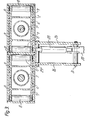
- the platform 2 is divided by a central partition 5 into two longitudinal chambers of rectangular cross-section, in which two horizontal bars 6 are slidably mounted ( Figures 2 and 3).
- Each horizontal bar is formed from two robust side-by-side I sections, of which the adjacent flanges are welded together to define a housing for a double acting hydraulic cylinder-piston unit 7.
- each I section of each bar 6 there is rotatably mounted a set of equidistant idle rollers 8 which contact the inner face of the corresponding vertical wall of the containing chamber for the bar 6.
- slide pads 9 for the bar 6 are disposed on the inner faces of the horizontal walls of said containing chamber.
- the two cylinder-piston units 7 are positioned in opposite directions, and their bodies are hinged in proximity to the closed ends of the two containing chambers for the bars 6.
- each bar 6, to which the rod of the corresponding cylinder-piston unit 7 is hinged, is rigid with the base of a box upright 10 which extends above the platform 2.
- the upright 10 houses a slider 11 which is analogous to the previously described horizontal bars 6.
- each slider 11 is composed of two robust side-by-side I sections welded together and guided within their box upright by respective idle rollers 88 and slide pads 99.
- a double acting hydraulic cylinder-piston unit 77 In the central chamber of the slider 11 there is provided a double acting hydraulic cylinder-piston unit 77, the body of which is pivoted to the top of the upright 10.
- the free end of the rod of said cylinder-piston unit 77 comprises a plate 12 disposed transversely to the platform 2 and inserted into a slot in a socket 13 of rectangular cross-section branching from the casing of a crawler track 14.
- the crawler tracks 14 are each provided with an independent drive constituted by a suitable hydraulic motor, and because their distance apart is adjustable they can lie straddling a railway track portion 3 or switch 4 in order to travel along the respective ballast portions.
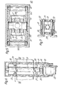
- These telescopic columns which extend above and below the platform 2, each consist of an outer hollow member 18 of rectangular cross-section which is rigid with the platform and in which there is slidably mounted an inner hollow member 19, which is also of rectangular cross-section ( Figures 6 and 7) and is guided by suitable slide pads 20 rigid with the outer hollow member.
- a double acting hydraulic cylinder-piston unit 21 of which the body is hinged to the top of the fixed element of the corresponding column, while its rod is hinged to the lower end part of the mobile element of said column.
- a flanged wheel 22 On the lower end of the inner hollow member 19 there is provided a flanged wheel 22, which in the illustrated example is shown idle but which according to the invention can also be provided with an independent drive such as a hydraulic motor.
- the inner hollow member 19 is provided both lowerly and upperly with four through bores 23.
- the two concentric hollow members 18 and 19 can be locked axially by means of two pins 24 which are inserted through said bores and which each comprise a small anti-withdrawal appendix designed for insertion into a suitable seat in the outer hollow member 19 ( Figure 7).
- the flanged wheels 22 When in their completely emerged position, but with the crawler tracks 14 completely retracted, the flanged wheels 22 are designed to run on the rails of a railway line.
- Two facing sets of equidistant through bores 27 are provided along the upper edges of said plates 26.
- the said set of bores are provided for adjusting the distance apart of two double acting hydraulic cylinder-piston units 28, of which the bodies are pivoted to the plates 26 by two extractable pins 29 provided with suitable positioning spacers.
- the cylinder-piston units are inclined towards the opposite side zones of the operational unit, i..e. towards the crawler tracks l4,and their rods are pivoted at the rear to two profiled lifting and transportation hooks 30, of which the pointed ends face said side zones.
- the upper ends of the hooks 30 are pivoted, by two extractable pins 31 provided with suitable spacers, to the upper edges of the two plates 26 where two facing sets of equidistant through bores 32 are provided.
- the distance between centres of the through bores 32 is slightly greater than that of the through bores 27, and the presence of the bores 32 enables the distance between the two hooks 30 to be adjusted according to the operating position set for the cylinder-piston units 28.
- the two cylinder-piston units 21 and the respective hooks 30 are symmetrical about the central dividing plane through the two plates 26, so as to prevent any interference between said members.
- either both or only one of the profiled hooks 30 can be disposed inversely if required or considered suitable, so as to be able to operate from the outside inwards.
- the hydraulic distributor is operated manually, but said hydraulic devices can also be operated by means of a centralised electrical control system.
- the crawler tracks 14 are completely raised and can be left projecting from the platform 2 by any desired distance.
- the described machine satisfies the overall outline dimensions allowable for rail transport, so that it can be towed along railway lines, can be loaded and transported on railway trucks in elements, and can also be loaded and transported on flat rail cars.
- the machine according to the invention can be provided with independent drive for its autonomous transfer from one operational zone to another, even over long distances.
Landscapes
- Engineering & Computer Science (AREA)
- Architecture (AREA)
- Civil Engineering (AREA)
- Structural Engineering (AREA)
- Machines For Laying And Maintaining Railways (AREA)
- Keying Circuit Devices (AREA)
- Lock And Its Accessories (AREA)
- Railway Tracks (AREA)
- Train Traffic Observation, Control, And Security (AREA)
Priority Applications (1)
| Application Number | Priority Date | Filing Date | Title |
|---|---|---|---|
| AT82200555T ATE15512T1 (de) | 1981-05-22 | 1982-05-07 | Vorrichtung zum verlegen von weichen und gleisabschnitten. |
Applications Claiming Priority (2)
| Application Number | Priority Date | Filing Date | Title |
|---|---|---|---|
| IT46846/81A IT1150411B (it) | 1981-05-22 | 1981-05-22 | Macchina per la sostituzione di devitoi ferroviari e tratti di binario in gener |
| IT4684681 | 1981-05-22 |
Publications (2)
| Publication Number | Publication Date |
|---|---|
| EP0066312A1 true EP0066312A1 (de) | 1982-12-08 |
| EP0066312B1 EP0066312B1 (de) | 1985-09-11 |
Family
ID=11259602
Family Applications (1)
| Application Number | Title | Priority Date | Filing Date |
|---|---|---|---|
| EP82200555A Expired EP0066312B1 (de) | 1981-05-22 | 1982-05-07 | Vorrichtung zum Verlegen von Weichen und Gleisabschnitten |
Country Status (5)
| Country | Link |
|---|---|
| US (1) | US4516503A (de) |
| EP (1) | EP0066312B1 (de) |
| AT (1) | ATE15512T1 (de) |
| DE (1) | DE3266142D1 (de) |
| IT (1) | IT1150411B (de) |
Cited By (7)
| Publication number | Priority date | Publication date | Assignee | Title |
|---|---|---|---|---|
| EP0084298A1 (de) * | 1981-10-27 | 1983-07-27 | Andrea Tedeschi | Portal zum Aufnehmen und Verlegen von Gleisen, insbesondere Weichen |
| FR2538425A1 (fr) * | 1982-12-24 | 1984-06-29 | Sig Schweiz Industrieges | Machine ferroviaire pour le deblaiement et l'aplanissement du ballast |
| FR2546924A1 (fr) * | 1983-06-03 | 1984-12-07 | Matisa Materiel Ind Sa | Machine ferroviaire pour la pose et la depose de troncons ou d'appareils de voie montes |
| FR2546923A1 (fr) * | 1983-06-03 | 1984-12-07 | Matisa Materiel Ind Sa | Machine ferroviaire pour la pose et la depose de troncons ou d'appareils de voie montes |
| US4538722A (en) * | 1983-03-30 | 1985-09-03 | Mcnally Pittsburg, Inc. | Conveyor shifting apparatus and process |
| AU571295B2 (en) * | 1984-04-10 | 1988-04-14 | Franz Plasser Bahnbaumaschinen-Industriegesellschaft M.B.H. | Travelling machine for taking up and laying track panels |
| EP2133469A3 (de) * | 2008-06-10 | 2013-01-23 | Tecsa Empresa Constructora, S.A. | Maschine zum Abladen und Positionierung von Schienen auf Schwellen von Eisenbahnschienen |
Families Citing this family (8)
| Publication number | Priority date | Publication date | Assignee | Title |
|---|---|---|---|---|
| AT383164B (de) * | 1984-10-31 | 1987-05-25 | Plasser Bahnbaumasch Franz | Schienenwagen zum auswechseln oder verlegen bzw. abbauen, sowie zum transportieren von gleisjochen |
| US4683969A (en) * | 1985-09-27 | 1987-08-04 | Littau Eugene G | Dimensionally-adjustable straddle-type crop-working vehicle |
| AT388000B (de) * | 1986-04-18 | 1989-04-10 | Plasser Bahnbaumasch Franz | Fahrbare anlage zum aufnehmen oder verlegen sowie transportieren von gleisjochen |
| FI94447C (fi) * | 1993-05-07 | 1995-09-11 | Desec Instmsto | Nostolaite raide-elementin käsittelemiseen |
| EP1799909B1 (de) * | 2004-08-20 | 2016-03-09 | Loram Maintenance Of Way, Inc. | Langschienen-abnehmer- und -ablieferungssystem |
| AT501271B8 (de) * | 2004-11-22 | 2007-02-15 | Plasser Bahnbaumasch Franz | Portalkran zum transportieren von gleisjochen |
| KR100721916B1 (ko) | 2006-08-18 | 2007-05-28 | 한국철도공사 | 스프링 체결장치 |
| RU2569451C2 (ru) * | 2014-02-28 | 2015-11-27 | Открытое Акционерное Общество "Российские Железные Дороги" | Способ укладки звеньев рельсошпальной решетки в кривых на участках, содержащих не менее двух путей, и траверса укладочного крана |
Citations (5)
| Publication number | Priority date | Publication date | Assignee | Title |
|---|---|---|---|---|
| DE563834C (de) * | 1931-04-10 | 1932-11-10 | Otto Taxis | Gleisverlegemaschine mit Raupenfahrwerken |
| US3299833A (en) * | 1963-03-28 | 1967-01-24 | John K Stewart | Externally engaging lifting jack frame |
| FR1479459A (fr) * | 1966-03-22 | 1967-05-05 | Perfectionnements apportés aux installations à portiques déplaçables sur voies de roulement, notamment pour travaux de renouvellement de voies ferrées | |
| DE2309930A1 (de) * | 1973-02-28 | 1974-08-29 | Juergen Frenzel | Vorrichtung zum verlegen von gleisabschnitten |
| FR2424361A1 (fr) * | 1978-04-25 | 1979-11-23 | Mercadier Paul | Procede et appareillages de renouvellement d'appareils de voie ferree |
Family Cites Families (6)
| Publication number | Priority date | Publication date | Assignee | Title |
|---|---|---|---|---|
| FR1355556A (fr) * | 1962-11-09 | 1964-03-20 | Dispositif de nivellement et de ripage des voies ferrées | |
| SU460348A1 (ru) * | 1972-08-18 | 1975-02-15 | Научно-исследовательский и проектно-конструкторский институт по добыче полезных ископаемых открытым способом | Устройство дл подъемки и рихтовки железнодорожного пути |
| US4143974A (en) * | 1976-01-22 | 1979-03-13 | Gkn Windsor Gmbh | Apparatus for plasticizing granular synthetic plastic materials |
| CH630680A5 (de) * | 1977-04-21 | 1982-06-30 | Plasser Bahnbaumasch Franz | Fahrbare einrichtung zum aufnehmen und/oder verlegen von aus schienen und schwellen bestehenden gleisjochen, weichenjochen oder ganzen weichen. |
| US4240354A (en) * | 1978-06-01 | 1980-12-23 | Newman Timothy L | Truck mounted railroad crane rail gear assembly |
| US4266904A (en) * | 1979-05-31 | 1981-05-12 | Raygo, Inc. | Adjustable load lifting spreader frame |
-
1981
- 1981-05-22 IT IT46846/81A patent/IT1150411B/it active
-
1982
- 1982-05-07 EP EP82200555A patent/EP0066312B1/de not_active Expired
- 1982-05-07 AT AT82200555T patent/ATE15512T1/de not_active IP Right Cessation
- 1982-05-07 DE DE8282200555T patent/DE3266142D1/de not_active Expired
- 1982-05-18 US US06/379,357 patent/US4516503A/en not_active Expired - Fee Related
Patent Citations (5)
| Publication number | Priority date | Publication date | Assignee | Title |
|---|---|---|---|---|
| DE563834C (de) * | 1931-04-10 | 1932-11-10 | Otto Taxis | Gleisverlegemaschine mit Raupenfahrwerken |
| US3299833A (en) * | 1963-03-28 | 1967-01-24 | John K Stewart | Externally engaging lifting jack frame |
| FR1479459A (fr) * | 1966-03-22 | 1967-05-05 | Perfectionnements apportés aux installations à portiques déplaçables sur voies de roulement, notamment pour travaux de renouvellement de voies ferrées | |
| DE2309930A1 (de) * | 1973-02-28 | 1974-08-29 | Juergen Frenzel | Vorrichtung zum verlegen von gleisabschnitten |
| FR2424361A1 (fr) * | 1978-04-25 | 1979-11-23 | Mercadier Paul | Procede et appareillages de renouvellement d'appareils de voie ferree |
Cited By (7)
| Publication number | Priority date | Publication date | Assignee | Title |
|---|---|---|---|---|
| EP0084298A1 (de) * | 1981-10-27 | 1983-07-27 | Andrea Tedeschi | Portal zum Aufnehmen und Verlegen von Gleisen, insbesondere Weichen |
| FR2538425A1 (fr) * | 1982-12-24 | 1984-06-29 | Sig Schweiz Industrieges | Machine ferroviaire pour le deblaiement et l'aplanissement du ballast |
| US4538722A (en) * | 1983-03-30 | 1985-09-03 | Mcnally Pittsburg, Inc. | Conveyor shifting apparatus and process |
| FR2546924A1 (fr) * | 1983-06-03 | 1984-12-07 | Matisa Materiel Ind Sa | Machine ferroviaire pour la pose et la depose de troncons ou d'appareils de voie montes |
| FR2546923A1 (fr) * | 1983-06-03 | 1984-12-07 | Matisa Materiel Ind Sa | Machine ferroviaire pour la pose et la depose de troncons ou d'appareils de voie montes |
| AU571295B2 (en) * | 1984-04-10 | 1988-04-14 | Franz Plasser Bahnbaumaschinen-Industriegesellschaft M.B.H. | Travelling machine for taking up and laying track panels |
| EP2133469A3 (de) * | 2008-06-10 | 2013-01-23 | Tecsa Empresa Constructora, S.A. | Maschine zum Abladen und Positionierung von Schienen auf Schwellen von Eisenbahnschienen |
Also Published As
| Publication number | Publication date |
|---|---|
| IT1150411B (it) | 1986-12-10 |
| US4516503A (en) | 1985-05-14 |
| DE3266142D1 (en) | 1985-10-17 |
| ATE15512T1 (de) | 1985-09-15 |
| IT8146846A1 (it) | 1982-11-22 |
| EP0066312B1 (de) | 1985-09-11 |
| IT8146846A0 (it) | 1981-05-22 |
Similar Documents
| Publication | Publication Date | Title |
|---|---|---|
| EP0066312B1 (de) | Vorrichtung zum Verlegen von Weichen und Gleisabschnitten | |
| US3840131A (en) | Storage and retrieval system | |
| US4595329A (en) | Process and installation for storing objects with automated handling | |
| JPS63189501A (ja) | 軌道盤を取上げ又は敷設しかつ運搬する機械 | |
| US4270655A (en) | Walking-beam conveyer | |
| CN116815650A (zh) | 一种预制箱梁横移施工方法及施工系统 | |
| US3556011A (en) | Railway car handling mechanism | |
| JPS62100325A (ja) | 積重ねをパレツトに載せるための装置 | |
| DE2013005A1 (de) | Einrichtung zur Lagerung von schwerem Stangenmatenal | |
| CN219566709U (zh) | 一种铁托盘箱的可转向链条输送装置 | |
| US4499664A (en) | Articulated mat revetment assembly machine | |
| EP0196701B1 (de) | Vorrichtung zur Behandlung und zum Ersetzen von Eisenbahnweichen und Eisenbahnschienenabschnitten im allgemeinen | |
| US4712283A (en) | Systems including at least one vertical turning machine or the like and at least two auxiliary stations | |
| US4608928A (en) | Track-bound carriage for an assembled track section | |
| WO1983004007A1 (en) | A device relating to a load-carrier | |
| US3592348A (en) | Load carrier-load support mechanism in automatic warehousing system | |
| US3494488A (en) | Overhead crane and article handling storage system | |
| CN102858474B (zh) | 用于至少成对地操纵和/或运输轧机机架的支撑辊和/或工作辊的装置 | |
| CN111375922B (zh) | 装配式建筑矩形钢管输送及组装系统 | |
| DE1559159C3 (de) | Parkanlage für Kraftfahrzeuge u.dgl | |
| CN220448858U (zh) | 用于盾构机后配套设备的辅助平移装置 | |
| CN222699334U (zh) | 一种货物装载对接装置 | |
| CN223813334U (zh) | 一种叉车架可调节的叉车 | |
| CN215754769U (zh) | 一种横向移载运输平台 | |
| CN214359885U (zh) | 一种直线机构 |
Legal Events
| Date | Code | Title | Description |
|---|---|---|---|
| PUAI | Public reference made under article 153(3) epc to a published international application that has entered the european phase |
Free format text: ORIGINAL CODE: 0009012 |
|
| AK | Designated contracting states |
Designated state(s): AT BE CH DE FR GB IT LI LU NL SE |
|
| 17P | Request for examination filed |
Effective date: 19830606 |
|
| RAP1 | Party data changed (applicant data changed or rights of an application transferred) |
Owner name: AMECA S.R.L. |
|
| ITF | It: translation for a ep patent filed | ||
| GRAA | (expected) grant |
Free format text: ORIGINAL CODE: 0009210 |
|
| AK | Designated contracting states |
Designated state(s): AT BE CH DE FR GB IT LI LU NL SE |
|
| REF | Corresponds to: |
Ref document number: 15512 Country of ref document: AT Date of ref document: 19850915 Kind code of ref document: T |
|
| REF | Corresponds to: |
Ref document number: 3266142 Country of ref document: DE Date of ref document: 19851017 |
|
| ET | Fr: translation filed | ||
| PLBE | No opposition filed within time limit |
Free format text: ORIGINAL CODE: 0009261 |
|
| STAA | Information on the status of an ep patent application or granted ep patent |
Free format text: STATUS: NO OPPOSITION FILED WITHIN TIME LIMIT |
|
| 26N | No opposition filed | ||
| ITTA | It: last paid annual fee | ||
| EPTA | Lu: last paid annual fee | ||
| EAL | Se: european patent in force in sweden |
Ref document number: 82200555.9 |
|
| PGFP | Annual fee paid to national office [announced via postgrant information from national office to epo] |
Ref country code: LU Payment date: 19960401 Year of fee payment: 15 |
|
| PGFP | Annual fee paid to national office [announced via postgrant information from national office to epo] |
Ref country code: SE Payment date: 19960430 Year of fee payment: 15 Ref country code: GB Payment date: 19960430 Year of fee payment: 15 |
|
| PGFP | Annual fee paid to national office [announced via postgrant information from national office to epo] |
Ref country code: AT Payment date: 19960507 Year of fee payment: 15 |
|
| PGFP | Annual fee paid to national office [announced via postgrant information from national office to epo] |
Ref country code: FR Payment date: 19960517 Year of fee payment: 15 Ref country code: CH Payment date: 19960517 Year of fee payment: 15 |
|
| PGFP | Annual fee paid to national office [announced via postgrant information from national office to epo] |
Ref country code: DE Payment date: 19960529 Year of fee payment: 15 |
|
| PGFP | Annual fee paid to national office [announced via postgrant information from national office to epo] |
Ref country code: NL Payment date: 19960531 Year of fee payment: 15 Ref country code: BE Payment date: 19960531 Year of fee payment: 15 |
|
| PG25 | Lapsed in a contracting state [announced via postgrant information from national office to epo] |
Ref country code: LU Free format text: LAPSE BECAUSE OF NON-PAYMENT OF DUE FEES Effective date: 19970507 Ref country code: GB Effective date: 19970507 Ref country code: AT Effective date: 19970507 |
|
| PG25 | Lapsed in a contracting state [announced via postgrant information from national office to epo] |
Ref country code: SE Effective date: 19970508 |
|
| PG25 | Lapsed in a contracting state [announced via postgrant information from national office to epo] |
Ref country code: LI Free format text: LAPSE BECAUSE OF NON-PAYMENT OF DUE FEES Effective date: 19970531 Ref country code: CH Free format text: LAPSE BECAUSE OF NON-PAYMENT OF DUE FEES Effective date: 19970531 Ref country code: BE Effective date: 19970531 |
|
| BERE | Be: lapsed |
Owner name: AMECA S.R.L. Effective date: 19970531 |
|
| PG25 | Lapsed in a contracting state [announced via postgrant information from national office to epo] |
Ref country code: NL Effective date: 19971201 |
|
| GBPC | Gb: european patent ceased through non-payment of renewal fee |
Effective date: 19970507 |
|
| REG | Reference to a national code |
Ref country code: CH Ref legal event code: PL |
|
| PG25 | Lapsed in a contracting state [announced via postgrant information from national office to epo] |
Ref country code: FR Free format text: LAPSE BECAUSE OF NON-PAYMENT OF DUE FEES Effective date: 19980130 |
|
| EUG | Se: european patent has lapsed |
Ref document number: 82200555.9 |
|
| NLV4 | Nl: lapsed or anulled due to non-payment of the annual fee |
Effective date: 19971201 |
|
| PG25 | Lapsed in a contracting state [announced via postgrant information from national office to epo] |
Ref country code: DE Free format text: LAPSE BECAUSE OF NON-PAYMENT OF DUE FEES Effective date: 19980203 |
|
| REG | Reference to a national code |
Ref country code: FR Ref legal event code: ST |