EP0066321A2 - Mustererkennungssystem - Google Patents
Mustererkennungssystem Download PDFInfo
- Publication number
- EP0066321A2 EP0066321A2 EP82200587A EP82200587A EP0066321A2 EP 0066321 A2 EP0066321 A2 EP 0066321A2 EP 82200587 A EP82200587 A EP 82200587A EP 82200587 A EP82200587 A EP 82200587A EP 0066321 A2 EP0066321 A2 EP 0066321A2
- Authority
- EP
- European Patent Office
- Prior art keywords
- subsignature
- signature
- target
- data
- signatures
- Prior art date
- Legal status (The legal status is an assumption and is not a legal conclusion. Google has not performed a legal analysis and makes no representation as to the accuracy of the status listed.)
- Granted
Links
Images




Classifications
-
- G—PHYSICS
- G01—MEASURING; TESTING
- G01B—MEASURING LENGTH, THICKNESS OR SIMILAR LINEAR DIMENSIONS; MEASURING ANGLES; MEASURING AREAS; MEASURING IRREGULARITIES OF SURFACES OR CONTOURS
- G01B11/00—Measuring arrangements characterised by the use of optical techniques
- G01B11/02—Measuring arrangements characterised by the use of optical techniques for measuring length, width or thickness
- G01B11/024—Measuring arrangements characterised by the use of optical techniques for measuring length, width or thickness by means of diode-array scanning
-
- G—PHYSICS
- G06—COMPUTING OR CALCULATING; COUNTING
- G06V—IMAGE OR VIDEO RECOGNITION OR UNDERSTANDING
- G06V10/00—Arrangements for image or video recognition or understanding
- G06V10/70—Arrangements for image or video recognition or understanding using pattern recognition or machine learning
- G06V10/74—Image or video pattern matching; Proximity measures in feature spaces
- G06V10/75—Organisation of the matching processes, e.g. simultaneous or sequential comparisons of image or video features; Coarse-fine approaches, e.g. multi-scale approaches; using context analysis; Selection of dictionaries
- G06V10/758—Involving statistics of pixels or of feature values, e.g. histogram matching
Definitions
- This invention relates to automated apparatus and methods for locating one or more particular points on a predetermined pattern with great accuracy. More particularly, the invention relates to apparatus for location of an integrated circuit chip precisely with respect to wire bonding apparatus, whereby leads may be attached to bonding pads formed as part of the microcircuit to connect it to the "outside world".
- the location of the die with respect to the reference location is either done by an operator or by automated machinery.
- the automated machinery available to date has not been adequate to satisfy the needs of the art.
- dies are supplied pre attached to the remainder of the integrated circuit of which they are the main component.
- the body of the integrated circuit itself can be accurately located with respect to the bonding machine.
- the precise location of the die on tbe-body-of the eventual integrated circuit device may vary from its nominal position by on the order of 10 mils in any direction and may additionally be angularly displaced from its proper orientation.
- the manufacturing capabilities of present day integrated circuit operations are such that it is important to be able to properly bond leads to integrated circuit chips displaced angularly on the order of + 7°, and linearly by up to 10 mils in any direction from the nominal position.
- the bonding pads to which the wires must be attached are typically only about 4 mils square. Accordingly, to locate these bonding pads with sufficient speed and accuracy to enable proper and rapid bonding is a task of technical complexity and one which has not been adequately performed in the prior art.
- Prior art pattern recognition systems are typically of the template matching kind, in which a stored portion of the pattern to be located is compared iteratively with various corresponding portions of the "target" pattern to be precisely located. See, e.g., U.S. Patent 4,200,861 to Hubach et al. This, it will be recognized, it is a very time consuming procedure, particularly where the target may be angularly displaced, as the relative movement of the stored portion required with respect to the target must be simultaneously made in both X and Y directions--that is, X and Y displacement cannot be determined independently by a template matching system, as both must be found simultaneously for a match to be detected.
- a further object of the invention is to provide a system for the recognition and precise location of a die to which lead wires are to be bonded which accomplishes its task in less time than previously possible.
- a further object of the invention is to provide a pattern recognition system in which even if the die is displaced outside the normal operating range of the instrument, an indication may still be provided to a host machine of its probable location so that upon retry the probability of proper location of the die is improved.
- a further object of the invention is to provide a system which does not require special targets, but accepts virtually any non-monotonous scene as unique reference locations.
- Yet another object of the invention is to provide a system for pattern recognition capable of detecting target rotation, thus improving the probability of properly locating the target.
- Another object of the invention is to provide a pattern recognition system useful in connection with integrated circuit components capable of precise location of other constitutent portions of an integrated circuit package, such as outer lead pads, ground or jumper chips and the like.
- Another object of the invention is to provide automated means for selection of an optimal reference image representation for comparison with a target image.
- An ultimate object of the invention is to provide a pattern recognition system for the precise location of integrated circuit dice with respect to a reference location which can be implemented relatively simply and inexpensively, and offer improved performance over prior art apparatus at substantially the same cost.
- the present invention comprises an apparatus for precise determination of the exact location of an object, for example, an integrated circuit die, with respect to a reference location.
- the apparatus is first operated in a teach mode in which a sample die is oriented by an operator with respect to a reference point.
- the apparatus optically scans the die and generates a unique representation of its visible appearance.
- the representation of the visible appearance is then analyzed to locate that portion corresponding to the most unique portion of the visible appearance of the die. This is performed in both X and Y directions and with respect to angular variation in the die position.
- the stored representation of the unique portion of the die is compared with a normalized representation of the target die, generating an error function; the minimum error function detected is that corresponding to the displacement from the nominal position. This may be performed several times with respect to both X and Y and with respect to differing portions of the target die displaced some distance from one another, so as to enable any errors in the identification to be detected and corrected.
- Fig. 1 shows a schematic view of a system for bonding wire leads to integrated circuit dice according to the invention.
- a die 10 provided with bonding pads 12 is affixed to an integrated circuit device indicated generally at 14.
- This device 14 is fitted with a plurality of lead connections 16, which are large enough that they can be attached to conventional terminals, such as in-line pins, and the like.
- the device 14 is shown schematically as provided with means 18 adapted for mating with index means 20 disposed on a host bonding machine.
- the host machine is provided with a table on which the index means 20 are disposed; the table is adapted to be movable in orthogonal directions, as indicated by the arrows, under the control of the host controller indicated generally at 22.
- Such devices, further including means for attaching wire leads to bonding pads as at 12, are known in the prior art and need not be further discussed here
- the apparatus for performing this operation comprises a source of light 24 and optical and camera means 26 which may comprise a video tube, a vidicon, or the like, adapted to sweep raster-fashion over an area corresponding to the area viewed.
- the analog signals output by the video image device 26 may be converted in an analog-to-digital converter 28 to digital representations of the light intensity falling on the camera at corresponding locations in known fashion.
- the field of the view of the image forming device 26 is divided into an N by M array of square areas on its surface, referred to as picture elements, or "pixels", and a digital number representative of the light intensity or gray level within that area is provided for each of the N x M pixels.
- pixels picture elements
- a 4-bit word providing 16 stages of light density is used to represent each pixel: the pixels are 0.00025" square, that is, there are four pixels per mil.
- the digitized samples are supplied to a microprocessor unit 30, supplied with random access memory means 32, which supplies signals to the host controller 22 as noted.
- a buffer amplifier 34 may also be provided to drive a video generator 36 which supplies a television screen 38 with a picture of what is viewed by the camera 26 to assist in the operator location of the chip with respect to reference locations during the teach operation, as will be outlined below.
- the microprocessor may also feed on-line storage means such as a floppy disk drive shown schematically at 40 for storage of information generated according to the method of the invention, as will be discussed in detail below.
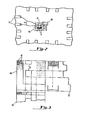
- Fig. 2 shows a more detailed view of an integrated circuit die 10 provided with bonding pads 12 as in Fig. 1. Also shown in Fig. 2 are the ends of lead connections 16 and wires 42 connecting the bonding pads 12 with the connections 16. Two fields of view of the video camera 26 are shown in outline form at 44 and 46. As noted these each "see” a portion of the total die 10. In the prior art, the operator might align a reference point on each target die with a cursor or other mark within the camera, and using this information then traverse a specific distance of the table containing the indexing means 18 to a second field of view as at 44 to confirm whether in fact the initial determination was performed-correctly.
- any errors in the initial identification will be magnified thus tending to show them up and enabling their correction.
- the actual size of the fields of view may be chosen in accordance with the size of the die, to allow this. According to the present invention, the operator need only visually align a die with a cursor once for each of the eyepoints 44 and 46 in the the teach mode; thereafter, this function is performed, in the run mode, without operator intervention, at high speed and with high reliability.
- Gray Level Light intensity code for each pixel, typically 4 bits, providing 16 gray levels.
- Guard Band That portion of the error function which is 8 or less units away from the home or originating position of the subsignature being tested. It exists to ignore low mismatch values associated with the neighborhood of origin.
- Error Function 'Series of sums of absolute differences using normalization and having N - M + 1 points, where N is the number of values in the signature, and M is the number values in the subsignature.
- Full Signature 240 sums obtained by the addition of the values of the central 240 coded gray levels of the horizontal lines or the 240 sums obtained by the addition of the gray level values of the center 240 columns of pixels.
- Teach area All the pixels in a central square area of an image during the teach operation. The area is 160 pixels wide and 160 pixels high.
- Restricted Signature 144 sums obtained from a corridor 144 pixels wide and either 200 or 160 deep.
- Subsignature 64 adjacent sums selected by the Max/ Min process from the teach window.
- Sum of Absolute Differences The result of comparison of 64 adjacent sums which are a portion of a full or a restricted signature with the 64 sums in a subsignature. Pair differences after normalization are accumulated without regard to sign, yielding a value inversely related to the similarity of the signature portion and the subsignature.
- Running Average Average values of 64 sums, recalculated for every group of 64 used.
- EF error function
- SF scaling factor
- Rotated Signature Series of sums obtained by accumulation of gray level codes associated with lines at a particular angle to the horizontal (for row sums) and vertical (for column sums). This is accomplished by using groups of 12 pixels in a row or column added to the next group which is displaced one row or column, and so on.
- Pointers 1. The address or location of the origin, the starting address, of a subsignature. 2. The address or location of the best fit or minimum mismatch of a subsignature as shown by an error function.
- Q value The minimum mismatch value in an error function indicative of the best fit made by a given subsignature with an entire signature.
- Scaled Q SQ is a Q value scaled to incorporate certain characteristics of the subsignature. Scaled Q is given by dividing the chosen Q by the scaling factor.
- Home Position The portion of a signature from which a given subsignature is drawn.
- SF Scaling Factor
- Snapshot The acquisition of a video frame. The request for a snapshot precedes and waits for the next occurring vertical synchronization pulse.
- Corridor An area array of pixels.
- the width of the array (looking from the signature) is always 144, which permits 81 adjacent groupings of 64.
- the depth is 240 for first pass, 200 for second pass, and 160 for third pass.
- the location of the corridor within the 240 x 240 field of view is determined by rules set forth in the RUN description.
- Reference Point The geometric center of the scene presented for storage as an Eye Point during TEACH. More precisely, it is the point on the surface of the die that coincides with the scene's center.
- Max/Min Selection During TEACH, one of the 97 possible groups of 64 adjacent sums derived from the window area is selected and stored as a subsignature (6 subsignatures per eye point). The selection process starts by generating error functions, i.e., functions of the sums of the absolute difference, resulting from comparisons of each candidate subsignature with the full signature. A minimum value O m i n in the region outside a guard band can be found in each error function. Among these minima, the maximum O max is found. The subsignature for which Q max was calculated is the most unique because it most poorly fits all portions of the signature other than its home position.
- Fig. 3 shows how the fields of view 44 and 46 are divided in the picture tube and are digitized to provide a digital representation of the visible surface of the die 10.
- Each of the fields of view is divided within the camera into a large number of picture elements or "pixels" 47.
- the total field of view is 240 x 320 pixels wide, of which a 240 pixel square area is typically used.
- each of the pixels 47 may be thought of as containing a four-bit digital number, the "gray level" representative of the relative brightness of the light falling on the video sensor in the corresponding position.
- the contents of all of the pixels in each of the rows are summed, and likewise with the columns; that is, as shown in Fig.
- X and Y “signatures” will be referred to respeatively as X and Y "signatures” herein.
- These signatures are both thus a 240 x 12-bit array of digital data. If such a series of 240 digital sums or signatures is converted to points on a graph, the X signature for a portion of a chip, as shown, might look something like the line 50 at the bottom of Fig. 3 while the Y signature could look something like that at the right of Fig. 3 at line 52: these may be thought of as graphical representations of the digital signatures.
- 64-element subsignatures are each iteratively compared with 81 64-element sub-portions of the total 240-element signature centered about their home position (except that from which they are taken, as discussed below).
- the comparison step measures the difference between the subsignature and each selected portion of the signature by summing the absolute value of the difference between each element of the subsignature and the corresponding element of the signature portion. A large sum indicates large differences or a poor fit; a lower sum implies a better match.
- Q min An indication of the quality of the best fit of each subsignature, i.e., the minimum mismatch with a portion of the main signature outside of the home region "guard band,” is saved and referred to as Q min.
- Omin is thus indicative of the degree to which the particular subsignature differs from the particular group of elements of the total signature of equal length which most nearly approximates the home position of the subsignature.
- Q min is therefore a measure of the degree-to which that subsignature could be used as a tool to help locate the position of a target die.
- a Q m i n is thus determined for each possible subsignature; that Q m i n which is largest, Q max , is then that which corresponds to the subsignature which is the most informative with respect to determining the location of a particular die.
- Qmax is Qmin for that subsi g nature which is the most unlike each portion of the total signature of like length outside the guard band to which it was compared. That subsignature is then used in the run mode of operation, for comparison with signatures generated with respect to each target die to be located.
- a subsignature SS N is iteratively compared with the total signature 52 N is a pointer indicating the location on the main signature from which the subsignature SS N was drawn.
- the correspondence is less exact, and accordingly the value of Q L --equal to the shaded area between SS N and the 64-element portion of the signature beginning at the location L--will be substantially greater. This is shown in Fig.
- this value is deleted from those compared to locate Q min, that Q L indicative of the closest identity reached between the particular subsignature SS N and any portion of the total signature.
- G 8.
- the largest of the Q min 's, Q max is Q min of that subsignature which least closely resembles each portion of the main signature (except itself), and is thus that subsignature which is most unique and likewise most informative and most useful in later identifying the precise location of a target die.
- a pointer indicative of the location of this subsignature within the total signature i.e., of N) is thus stored in the teach mode.
- Fig. 5b shows this process schematically--that Q min which is largest'is identified as Q max .
- the above process of finding the best sub signature for identifying a particular position on a die is repeated in the X and Y dimensions and is likewise repeated with respect to a "rotated" representation of the die.
- the die is effectively rotated through an angle of some 4.76° by the way in which the summation of the individual pixel values leading to the signatures is accomplished.
- the accomplishment of rotation through an angle of 4.76° may be accomplished very simply during the summing yielding the signatures by, e.g., adding the first 12 pixels in a given first column and moving over one column to the second column, adding the next 12 pixels, moving to the third column, adding the next 12 pixels, and so on.
- Fig. 7 graphically indicates results of comparison of a stored subsignature with a signature generated with respect to a target die.
- the subsignature is compared with each possible portion of the signature with the +40 pixel range of operation of the present embodiment of the invention.
- Q values are generated at each of the 81 stages in accordance with the summation process discussed above; that is,, Q is the sum of the absolute values of the difference between each one of the 64 stored values of the subsignature and the corresponding value of the subset of 64 of the total 240-element signature being examined.
- Q is thus indicative of the identity between the subsignature and that portion of the signature being examined.
- N being equal to the pointer of the location of the subsignature plus or minus a number ⁇ X of pixels
- N + ⁇ X thus pointing to the portion of the signature being compared with the subsignature
- the Q value will reach a minimum Q m i n indicating that correspondence has been found.
- ⁇ X is then the displacement in pixels of the die from the reference location N or "eyepoint", as defined by the subsignature SS N .
- This information may be fed to the host processor for attaching wire bonding leads at positions displaced AX from their nominal position. The process is repeated for rotated subsignatures stored during the teach mode.
- the X and Y displacements are thus determined independently of one another, thus satisfying one of the objects of the invention mentioned above. If N comparison of subsignatures are made in both X and Y, the total number of comparisons is 2N. If a template matching or other scheme in which X and Y comparisons are not independent were instead made, N 2 comparisons would have to be made to yield equally detailed image resolution.
- the process may be repeated at diagonal corners of the die for additional insurance purposes. It will be appreciated by those skilled in the art that if a 9 correction is necessary, this will be very thoroughly confirmed essentially by multiplication of the correction over the diagonal dimension of the die.
- Fig. 8 shows a detail of the flowchart of the teach operation. It is initialized as at 100 by setting N, the number of the subsignature being considered to 40, defining the 160 x 160 array of pixels, and L,. the location of the first point of the 81 64-element portions of the signature to which the Nth subsignature is being compared, equal to N - 40, while Q m i n is set to an arbitrarily large number and Q max is set to zero.
- a first subsignature to be tried, beginning at a location N and running through location N + 64, is brought from a RAM, in which the total signature is stored, into a subsignature RAM, at 102.
- the ith element of the Nth subsignature is referred to as SS N i.
- L is fetched (112), if it is not the last (110) and the process is repeated. If L is in the vicinity of N, as defined by a constant G, that is, if the subsignature is being compared to that area of the signature from which it was derived, this area is skipped over so that false indications of Q m i n are not generated, as at 114.
- the N latched may be taken to be the pointer of the most useful subsignature, while O max is indicative of how useful it is, as indicated at 126; that is, of its relative uniqueness.
- the process may then be repeated with respect to rotated axes as outlined above, and with respect to the other coordinate (128).
- a test may be performed as at 130 with respect to a subsignature found with respect to a first eyepoint of the camera by physically moving the die with respect to the camera and performing a. run operation as will be detailed below.
- the die is physically moved with respect to the camera to a second reference or "eye point" and the entire process repeated as at 132 to generate a second set of subsignatures, that is, one each in X and Y for a second reference point.
- Fig. 9 shows a detailed flowchart of the run operation.
- the maximum displacement of the die from its nominal position is a statistical function of manufacturing tolerances and the like; it is found in practice that an acceptably high number of dice fall within a + 40 pixel range from their nominal location. Accordingly, the subsignature generated as above in the teach mode need only be compared with areas of the signature disposed ⁇ 40 pixels from this reference area, which is useful in that the processing time involved in the run operation is minimized. Further, in this way any repetitive image having a frequency of less than 40 pixels does not cause erroneous identification.
- P m i n will point to the location of the best match, as noted at 160, and accordingly (P m i n - N) is indicative of AX, the displacement in pixels of the reference location from its nominal position.
- the process may be repeated and reperformed, with rotated signatures generated as above, with respect to the orthogonal coordinate, with restricted portions of the signatures, as detailed below in connection with Fig. 12, and reperformed at the second eye point, all as noted at 162 - 165.
- the absolute value of Q m i n is inversely related to the degree of accuracy to which the sub signature selected corresponds to the signature of the target die. If this value is insufficiently low to indicate that a proper correspondence is found, as indicated at 166, a reject signal is passed to the host at 168, whereupon further processing may be performed.
- the displacement ⁇ X for which an acceptable Q min is found is indicated to be + 40 pixels, as at 169. If so, a better fit may be found at a Ax slightly greater than + 40. This fact can be indicated to the host and the total die physically moved some distance in the direction thus indicated as at 170. Alternatively, a different range of signatures -40 ⁇ P ⁇ 40 can be selected for comparison.
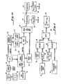
- a microprocessor 60 is fed with video signals from an analog-to-digital converter 62 fed with signals from a camera 64. Signals from the camera 64 are also fed to a video processing unit 66 and thence to a television 68 useful in the operator's initially setting a reference point and also simply to monitor the operation of the process of the invention.
- the signatures are actually generated in random access memory/accumulator units 70 and 72 for X and Y signatures respectively, fed by the analog-to-digital converter 62 via a corridor select gate 63, the operation of which is detailed below, in connection with Fig. 12.
- a possible modification to the embodiment of the invention described would involve replacement'of the camera and X and Y accumulators with a pair of cruciform linear scan arrays, either swept physically with respect to the die, to generate similar integrated, gray scale signature values, or provided with cylindrical optics for optical integration of gray scale values, for each axis.
- all the signatures, both X and Y, and the rotated versions thereof are contained in single registers; that is, the digital signals output by analog-to-digital converter 62 are simply fed into the accumulators 70 and 72 as required; the sums are computed in real time simultaneously with conversion of the individual analog picture light intensity signals into gray level digital format, so that no storage of all the values of all the elements of the video picture need ever be performed.
- Selection of the signals between the two RAM/accumulator units 70 and 72 is performed by multiplex unit 74 controlled by the microprocessor 60.
- a host processor 76 To the microprocessor 60 is also connected, via a host controller interface, a host processor 76, as discussed above, as is an additional RAM unit 78 for storage of a subsignature being processed.
- the summation of the absolute values of the differences between particular subsets of the signatures stored in one or the other of RAMs 70 and 72 and that stored in the sub signature RAM 78 is performed in a normalization and summing of the absolute difference unit 80, the details of which will be discussed below in connection with Fig. 11.
- each subsignature SS n is compared with 81 possible subsets of the total signature, and a Q value is generated for each of the possible positions. That is, for each of the 81 positions, a Q value is generated in the normalize and sum unit 80. Comparison is performed in comparator 84 between the Q m i n value previously determined to be the closest fit of that subsignature with a subset of the total signature, latched in latch 86.
- the value of Q m i n is compared in a second comparator 90 with the highest value of Q m i n previously determined, this value Q max being stored in a second latch 88.
- the latch 88 may also store the location of the subsignature yielding O max .
- the various summations used to yield the Q value that is, the summations of the absolute values of the differences between each element of a particular subsignature under consideration and the corresponding elements of a subset of a total signature under consideration are only meaningful if the two are scaled to one another by a normalization process. That is, for example, variation in the light intensity between the time at which the sub signature is generated and the target signature is generated may cause variations in the absolute values of the digitized signals which are summed to produce the signature. Alternatively, reflectivity of the dice can vary, while other circuit conditions can change for a variety of reasons. Accordingly, normalization is performed.
- this is performed simply by taking the average value of the 64 elements of the signature being considered together with an average value indicative of the 64 elements of the subsignature under consideration and cross-multiplying the two, thus performing a normalization function.
- Other means of normalization would, of course, be possible. Manipulations of the averages and other operands used in the normalization, other than cross multiplication are useable.
- Fig. 11 shows an enlarged view of the normalization and summing means 80.
- the signature array of interest is supplied as at 94 from either .of. RAMs 70 or 72..
- the subsignature array is supplied from the subsignature RAM 78.
- the signature array is fed through a delay means 96 which might be a 64-byte shift register, while the average value of the 64 elements of the signature is calculated in an average generator 98.
- This may in a preferred embodiment simply comprise the sum of the 64 values, for reasons which will be clear below, so that the average generator 98 may simply be an accumulator.
- the value output by the generator 98 is multiplied in a multiplier 99 by each individual element of the sub signature.
- the multiplied sub signature value is then fed to an absolute value/differencing unit 97 which is also supplied via delay 96 with each individual element of the signature, having been multiplied in a second multiplier 93 by the average of the subsignature elements, (or their total, as noted above), supplied from a subsignature average register 95. Then, in summing unit 85, the sum of the differences between each weighted subsignature element and the corresponding weighted signature element output by unit 97 is computed.
- the total sum yielded, Q NL is inversely related to the correspondence between the 64-element subsignature beginning at a pointer location N, as compared with 64 elements of the signature beginning with a pointer location L.
- the process is repeated with respect to the orthogonal orientation, and to rotated signatures, each derived by use of camera 64 and analog-to-digital converter 62 to generate a "snapshot" of the sample die with respect to each orientation as discussed above, to generate the canted subsignatures.
- the summation is performed with respect to the stepped columns at a rate determinative of the degree of canting desired.
- the six thus generated subsignatures are stored in a subsignature RAM 78.
- a subsignature RAM 78 Those skilled in the art will recognize that substantially the same hardware may be, and in a preferred embodiment is, used in performance of the run mode.
- the stored subsignatures are fed to a normalizing and summing unit 80 as above for comparison with similarly-generated snapshots of the target die.
- Q values are generated by comparison of each subsignature with each possible subset of the total signature, and X and Y pointers indicative of the location of the subset of the X and Y signatures yielding the minimum Q, i.e., maximum correspondence, are then indicative of the degree of displacement ⁇ X and AY of the target die with respect to the reference die: that is, for example, N - L, where L is the pointer indicating the beginning of the subset of the X signature yielding the minimum Q when compared with the subsignature beginning at location N, is equal to AX, in pixels.
- the amount of the area of the taught region,.or of the target region, which can be directly compared to a subsignature is limited by the width of the subsignature. Therefore, for a given area of interest, the outermost portions defined by half the width of the subsignature cannot be the center of the subsignature.
- This fact is exploited in the present invention to provide compensation for possible simultaneous variations in X and Y displacement of a die, or other target object, from its nominal position.
- a target is displaced in the X direction, i.e., along a horizontal row, and an integration is performed over each set of vertical columns, the result will be displaced from the nominal integrated position.
- the subset of possible subsignatures which are compared with a stored subsignature is gradually limited over plural "passes", that is, successive similar operations, to those areas previously identified as likely eyepoint-correspondent locations.
- the sub areas of the total field of view which are compared with the stored subsignature vary from pass to pass in accordance with the information about the position of the target found with respect to the orthogonal direction, so that the correspondence gets gradually more likely to be correct, while limiting the amount of comparison operations required to be performed.
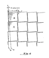
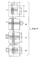
- F ig. 12a the overall area viewed by the camera is shown as 240 pixels square.
- the central area 160 pixels square is used in generation of the subsignatures and a subsignature centered about some pointer in X, N X and another about a pointer in Y, Ny, will be found in the teach operation.
- the subsignature centered about N X will be compared with areas of the signature in the range Nx - 40 and N X + 40, by the entire 240-pixel Y depth. While this will affect the accuracy of the comparison to some degree (as the subsignature is calculated over 160 of the 240 pixels considered in Run), it does eliminate variations in Y from affecting the X determination.
- the process is then performed similarly in the Y direction, centered about Ny + 40 pixels as indicated.
- the area which is doubly shaded in Fig. 12b is thus the nominal position of the center of the subsignatures.
- the actual position of the point corresponding to Nx is found to be N X ', as indicated by a dotted line, and that Ny. is Ny', similarly indicated.
- a smaller area or corridor some 200 pixels deep in both X and Y will be allowed to contribute to the portions of the signatures compared to the subsignatures, centered about N X ' and Ny', respectively, thus yielding shaded areas for comparison as shown in Fig. 12c.
- the extent of the "corridors" thus defined is 200 pixels in the second pass.
- the pattern recognition system requires picture information obtained from an optical system comprising a light source, optical means and a camera.
- the camera can use either a vidicon, solid state array, or like device to generate segmented analog representations of light intensity following thereon. These may be digitized to yield a numeric value for ready control.
- Profiles or signatures are used to uniquely characterize a particular scene and its position. Signatures are obtained by integration of the intensity values along columns of picture elements, or "pixels", and along each row of pixels.
- the displacement measurement is accomplished by iterative comparison of a particularly selected segment of the total signature, i.e., a subsignature, with a larger signature, looking for the best match.
- the search for the minimum mismatch gives accuracy to the nearest pixel.
- the minimum mismatch of Q i.e., its actual amplitude, has a relative value in judging the confidence of the recognition, which may be referred to as the "scaled-Q". Its computation compensates for variation in the sub signatures obtainable from different dice.
- the scaled-Q value is compared with a predetermined threshold either to reject or accept a particular scene.
- Displacement of a scene from a remote position can occur in X and Y and in 0, i.e., upon rotation of the die.
- X one notes only vertical features since they are integrated without measurement of the distance between them.
- column integration can be performed without loss of data useful in horizontal measurement.
- row integration can be done without interfering with the vertical measurement.
- the result of the integration provides a unique profile; a subset of this profile is chosen so that its length overlaps various scenes so as to enable accurate recognition. Integration of the digitized analog signals also reduces the effect of random electronic and camera noise which may be significant, particularly with respect to the use of vidicon-type cameras. In this connection, note that while noise and the like may affect the actual value of Q, the accuracy of the pointers generated is unaffected by such noise.
- Normalization is performed in order to enable accurate comparison of subsignature to signatures to be made, by compensating for possible differences in illumination and between the taught and target scenes. This also compensates for signatures obtained from different depth columns or rows in the event that a restricted portion of the scene is desired to be viewed during a particular part of the processing operation. Normalization thus permits comparison of the substantial shape of the signature, rather than of its precise amplitude.
- an effectively rotated subsignature can be generated in both X and Y and this can be used to accommodate slight angular displacements of the die with respect to its reference position.
- the novel integration over rows and columns of pixels in the signature generation step avoids template matching, thus reducing the number of comparisons required to locate a particular subimage with respect to a total image from N 2 to 2N, as compared with typical template matching schemes.
Landscapes
- Engineering & Computer Science (AREA)
- Theoretical Computer Science (AREA)
- General Physics & Mathematics (AREA)
- Computer Vision & Pattern Recognition (AREA)
- Physics & Mathematics (AREA)
- Health & Medical Sciences (AREA)
- Computing Systems (AREA)
- Databases & Information Systems (AREA)
- Evolutionary Computation (AREA)
- General Health & Medical Sciences (AREA)
- Medical Informatics (AREA)
- Software Systems (AREA)
- Artificial Intelligence (AREA)
- Multimedia (AREA)
- Image Analysis (AREA)
- Image Processing (AREA)
- Character Discrimination (AREA)
Priority Applications (1)
| Application Number | Priority Date | Filing Date | Title |
|---|---|---|---|
| AT82200587T ATE26341T1 (de) | 1981-05-18 | 1982-05-14 | Mustererkennungssystem. |
Applications Claiming Priority (2)
| Application Number | Priority Date | Filing Date | Title |
|---|---|---|---|
| US06/264,481 US4441205A (en) | 1981-05-18 | 1981-05-18 | Pattern recognition system |
| US264481 | 1988-10-28 |
Publications (3)
| Publication Number | Publication Date |
|---|---|
| EP0066321A2 true EP0066321A2 (de) | 1982-12-08 |
| EP0066321A3 EP0066321A3 (en) | 1984-07-25 |
| EP0066321B1 EP0066321B1 (de) | 1987-04-01 |
Family
ID=23006255
Family Applications (1)
| Application Number | Title | Priority Date | Filing Date |
|---|---|---|---|
| EP82200587A Expired EP0066321B1 (de) | 1981-05-18 | 1982-05-14 | Mustererkennungssystem |
Country Status (4)
| Country | Link |
|---|---|
| US (1) | US4441205A (de) |
| EP (1) | EP0066321B1 (de) |
| JP (1) | JPH0658682B2 (de) |
| AT (1) | ATE26341T1 (de) |
Cited By (8)
| Publication number | Priority date | Publication date | Assignee | Title |
|---|---|---|---|---|
| GB2133140A (en) * | 1982-12-27 | 1984-07-18 | Usm Corp | Component inserting machine |
| GB2146427A (en) * | 1983-08-01 | 1985-04-17 | Canon Kk | Semiconductor manufacture |
| EP0157148A1 (de) * | 1984-02-25 | 1985-10-09 | Robert Prof. Dr. Massen | Verfahren zur berührungslosen Messung der Länge eines bewegten Gegenstandes und Messvorrichtung zur Durchführung des Verfahrens |
| EP0160160A1 (de) * | 1984-03-09 | 1985-11-06 | International Business Machines Corporation | Video-Messsystem zur orthogonalen Lagebestimmung |
| US4712057A (en) * | 1983-05-25 | 1987-12-08 | Battelle Memorial Institute | Method of examining and testing an electric device such as an integrated or printed circuit |
| EP0345984A3 (en) * | 1988-06-07 | 1990-07-25 | Contrologic, Incorporated | Non-contact optical gauge |
| GB2247312A (en) * | 1990-07-16 | 1992-02-26 | Univ Brunel | Surface Inspection |
| DE29510334U1 (de) * | 1995-06-26 | 1995-10-26 | AQS Dimensionale Meßtechnik GmbH, Hallein/Salzburg | System zur zweidimensionalen Vermessung planer Objekte |
Families Citing this family (92)
| Publication number | Priority date | Publication date | Assignee | Title |
|---|---|---|---|---|
| DE3481144D1 (de) * | 1983-04-11 | 1990-03-01 | Komatsu Mfg Co Ltd | Verfahren zum identifizieren von objekten. |
| JPS59226981A (ja) * | 1983-06-08 | 1984-12-20 | Fujitsu Ltd | パタ−ンマツチング方法および装置 |
| JPH0754549B2 (ja) * | 1984-09-19 | 1995-06-07 | 株式会社日立製作所 | パターンマッチング用標準パターンの作成方法 |
| US4907287A (en) * | 1985-10-16 | 1990-03-06 | Hitachi, Ltd. | Image correction system for scanning electron microscope |
| US5067162A (en) * | 1986-06-30 | 1991-11-19 | Identix Incorporated | Method and apparatus for verifying identity using image correlation |
| US4805123B1 (en) * | 1986-07-14 | 1998-10-13 | Kla Instr Corp | Automatic photomask and reticle inspection method and apparatus including improved defect detector and alignment sub-systems |
| US4817169A (en) * | 1987-04-14 | 1989-03-28 | Nippon Sheet Glass Co., Ltd. | Page segmentor |
| US4955063A (en) * | 1987-04-14 | 1990-09-04 | Nippon Sheet Glass Co., Ltd. | Vector display apparatus |
| US5033105A (en) * | 1987-08-11 | 1991-07-16 | Apple Computer | Video compression algorithm |
| US4853968A (en) * | 1987-09-21 | 1989-08-01 | Kulicke & Soffa Industries, Inc. | Pattern recognition apparatus and method |
| US5119435A (en) * | 1987-09-21 | 1992-06-02 | Kulicke And Soffa Industries, Inc. | Pattern recognition apparatus and method |
| US4811090A (en) * | 1988-01-04 | 1989-03-07 | Hypervision | Image emission microscope with improved image processing capability |
| JP2505534B2 (ja) * | 1988-06-03 | 1996-06-12 | 日立精工株式会社 | 工具検出装置 |
| US4984280A (en) * | 1988-06-08 | 1991-01-08 | Laurel Bank Machines Co., Ltd. | Bill discriminating apparatus |
| US4972311A (en) * | 1988-08-15 | 1990-11-20 | Kulicke And Soffa Industries Inc. | X-Y table error mapping apparatus and method |
| US5218605A (en) * | 1990-01-31 | 1993-06-08 | Hewlett-Packard Company | Software modules for testing computer hardware and software |
| US5146102A (en) * | 1990-02-22 | 1992-09-08 | Kabushiki Kaisha Toshiba | Fingerprint image input apparatus including a cylindrical lens |
| JP2691789B2 (ja) * | 1990-03-08 | 1997-12-17 | 三菱電機株式会社 | はんだ印刷検査装置 |
| AU645123B2 (en) * | 1990-09-24 | 1994-01-06 | Fmc Corporation | Automatic windowing for article recognition |
| FR2673041A1 (fr) * | 1991-02-19 | 1992-08-21 | Gemplus Card Int | Procede de fabrication de micromodules de circuit integre et micromodule correspondant. |
| JPH04346187A (ja) * | 1991-05-23 | 1992-12-02 | Matsushita Electric Ind Co Ltd | 被検出物の良否判定方法 |
| US5343409A (en) * | 1991-08-29 | 1994-08-30 | Hewlett-Packard Company | System and method for probing object resources in a window server environment |
| US5322207A (en) * | 1993-05-03 | 1994-06-21 | Micron Semiconductor Inc. | Method and apparatus for wire bonding semiconductor dice to a leadframe |
| US5350106A (en) | 1993-05-07 | 1994-09-27 | Micron Semiconductor, Inc. | Semiconductor wire bonding method |
| US6748101B1 (en) | 1995-05-02 | 2004-06-08 | Cummins-Allison Corp. | Automatic currency processing system |
| US6363164B1 (en) | 1996-05-13 | 2002-03-26 | Cummins-Allison Corp. | Automated document processing system using full image scanning |
| JP3106345B2 (ja) * | 1995-10-23 | 2000-11-06 | 株式会社新川 | ワイヤボンディング装置 |
| US6661910B2 (en) | 1997-04-14 | 2003-12-09 | Cummins-Allison Corp. | Network for transporting and processing images in real time |
| US8950566B2 (en) | 1996-05-13 | 2015-02-10 | Cummins Allison Corp. | Apparatus, system and method for coin exchange |
| US7187795B2 (en) | 2001-09-27 | 2007-03-06 | Cummins-Allison Corp. | Document processing system using full image scanning |
| US8204293B2 (en) | 2007-03-09 | 2012-06-19 | Cummins-Allison Corp. | Document imaging and processing system |
| US8162125B1 (en) | 1996-05-29 | 2012-04-24 | Cummins-Allison Corp. | Apparatus and system for imaging currency bills and financial documents and method for using the same |
| US7903863B2 (en) | 2001-09-27 | 2011-03-08 | Cummins-Allison Corp. | Currency bill tracking system |
| US20050276458A1 (en) | 2004-05-25 | 2005-12-15 | Cummins-Allison Corp. | Automated document processing system and method using image scanning |
| DE19633693C1 (de) * | 1996-08-21 | 1997-11-20 | Max Planck Gesellschaft | Verfahren und Vorrichtung zur Erfassung von Targetmustern in einer Textur |
| SE509327C2 (sv) * | 1996-11-01 | 1999-01-11 | C Technologies Ab | Sätt och anordning för registrering av tecken med hjälp av en penna |
| US8478020B1 (en) | 1996-11-27 | 2013-07-02 | Cummins-Allison Corp. | Apparatus and system for imaging currency bills and financial documents and method for using the same |
| US6507672B1 (en) * | 1997-09-10 | 2003-01-14 | Lsi Logic Corporation | Video encoder for digital video displays |
| US6173213B1 (en) | 1998-05-11 | 2001-01-09 | Ellison Machinery Company | Motorized inbound laser orientation and wheel recognition station |
| US7016539B1 (en) | 1998-07-13 | 2006-03-21 | Cognex Corporation | Method for fast, robust, multi-dimensional pattern recognition |
| US6608920B1 (en) * | 1998-10-29 | 2003-08-19 | Applied Materials, Inc. | Target acquisition technique for CD measurement machine |
| US6571006B1 (en) * | 1998-11-30 | 2003-05-27 | Cognex Corporation | Methods and apparatuses for measuring an extent of a group of objects within an image |
| JP4454075B2 (ja) * | 1999-08-27 | 2010-04-21 | 株式会社ルネサステクノロジ | パターンマッチング方法 |
| US6999614B1 (en) * | 1999-11-29 | 2006-02-14 | Kla-Tencor Corporation | Power assisted automatic supervised classifier creation tool for semiconductor defects |
| US6577019B1 (en) * | 2000-01-21 | 2003-06-10 | Micron Technology, Inc. | Alignment and orientation features for a semiconductor package |
| US8701857B2 (en) | 2000-02-11 | 2014-04-22 | Cummins-Allison Corp. | System and method for processing currency bills and tickets |
| US6468813B1 (en) | 2000-05-01 | 2002-10-22 | Advanced Semiconductor Engineering, Inc. | Method of automatically identifying and skipping defective work pieces for wire-bonding operation |
| US7000828B2 (en) | 2001-04-10 | 2006-02-21 | Cummins-Allison Corp. | Remote automated document processing system |
| US6959112B1 (en) | 2001-06-29 | 2005-10-25 | Cognex Technology And Investment Corporation | Method for finding a pattern which may fall partially outside an image |
| US7647275B2 (en) | 2001-07-05 | 2010-01-12 | Cummins-Allison Corp. | Automated payment system and method |
| US8437530B1 (en) | 2001-09-27 | 2013-05-07 | Cummins-Allison Corp. | Apparatus and system for imaging currency bills and financial documents and method for using the same |
| US8428332B1 (en) | 2001-09-27 | 2013-04-23 | Cummins-Allison Corp. | Apparatus and system for imaging currency bills and financial documents and method for using the same |
| US8944234B1 (en) | 2001-09-27 | 2015-02-03 | Cummins-Allison Corp. | Apparatus and system for imaging currency bills and financial documents and method for using the same |
| US8433123B1 (en) | 2001-09-27 | 2013-04-30 | Cummins-Allison Corp. | Apparatus and system for imaging currency bills and financial documents and method for using the same |
| US8437529B1 (en) | 2001-09-27 | 2013-05-07 | Cummins-Allison Corp. | Apparatus and system for imaging currency bills and financial documents and method for using the same |
| US7283659B1 (en) | 2002-01-09 | 2007-10-16 | Kla-Tencor Technologies Corporation | Apparatus and methods for searching through and analyzing defect images and wafer maps |
| US6896118B2 (en) | 2002-01-10 | 2005-05-24 | Cummins-Allison Corp. | Coin redemption system |
| US6506614B1 (en) | 2002-01-29 | 2003-01-14 | Tyco Electronics Corporation | Method of locating and placing eye point features of a semiconductor die on a substrate |
| US8171567B1 (en) | 2002-09-04 | 2012-05-01 | Tracer Detection Technology Corp. | Authentication method and system |
| US8627939B1 (en) | 2002-09-25 | 2014-01-14 | Cummins-Allison Corp. | Apparatus and system for imaging currency bills and financial documents and method for using the same |
| US7320009B1 (en) | 2003-03-28 | 2008-01-15 | Novell, Inc. | Methods and systems for file replication utilizing differences between versions of files |
| US20040218006A1 (en) * | 2003-04-30 | 2004-11-04 | Dickerson Stephen Lang | Scanning apparatus |
| US7190834B2 (en) * | 2003-07-22 | 2007-03-13 | Cognex Technology And Investment Corporation | Methods for finding and characterizing a deformed pattern in an image |
| US8081820B2 (en) | 2003-07-22 | 2011-12-20 | Cognex Technology And Investment Corporation | Method for partitioning a pattern into optimized sub-patterns |
| US7565034B2 (en) * | 2004-06-17 | 2009-07-21 | Avago Technologies Ecbu Ip (Singapore) Pte. Ltd. | Determination of a navigation window in an optical navigation system |
| US20060047462A1 (en) * | 2004-08-31 | 2006-03-02 | Picciotto Carl E | Displacement estimation system and method |
| US7085673B2 (en) * | 2004-08-31 | 2006-08-01 | Hewlett-Packard Development Company, L.P. | Displacement estimation system and method |
| US8437502B1 (en) | 2004-09-25 | 2013-05-07 | Cognex Technology And Investment Corporation | General pose refinement and tracking tool |
| US20060174084A1 (en) * | 2005-01-31 | 2006-08-03 | Suban Krishnamoorthy | Storage system configuration validation |
| US20060173664A1 (en) * | 2005-01-31 | 2006-08-03 | Suban Krishnamoorthy | SAN modeling |
| US7946406B2 (en) | 2005-11-12 | 2011-05-24 | Cummins-Allison Corp. | Coin processing device having a moveable coin receptacle station |
| US7980378B2 (en) | 2006-03-23 | 2011-07-19 | Cummins-Allison Corporation | Systems, apparatus, and methods for currency processing control and redemption |
| US7929749B1 (en) | 2006-09-25 | 2011-04-19 | Cummins-Allison Corp. | System and method for saving statistical data of currency bills in a currency processing device |
| US8538123B1 (en) | 2007-03-09 | 2013-09-17 | Cummins-Allison Corp. | Apparatus and system for imaging currency bills and financial documents and method for using the same |
| US8417017B1 (en) | 2007-03-09 | 2013-04-09 | Cummins-Allison Corp. | Apparatus and system for imaging currency bills and financial documents and method for using the same |
| JP5873611B2 (ja) * | 2007-03-13 | 2016-03-01 | クリック アンド ソッファ インダストリーズ、インク. | ワイヤーボンディング用に目標アイポイントを教示する方法およびそれに関連した半導体処理操作 |
| WO2009026803A1 (en) * | 2007-08-27 | 2009-03-05 | Yuvad Technologies Co., Ltd. | A method for identifying motion video content |
| WO2009140816A1 (en) * | 2008-05-21 | 2009-11-26 | Yuvad Technologies Co., Ltd. | A method for facilitating the archiving of video content |
| US8488835B2 (en) * | 2008-05-21 | 2013-07-16 | Yuvad Technologies Co., Ltd. | System for extracting a fingerprint data from video/audio signals |
| WO2009140818A1 (en) * | 2008-05-21 | 2009-11-26 | Yuvad Technologies Co., Ltd. | A system for facilitating the archiving of video content |
| WO2009140819A1 (en) * | 2008-05-21 | 2009-11-26 | Yuvad Technologies Co., Ltd. | A system for facilitating the search of video content |
| WO2009140822A1 (en) * | 2008-05-22 | 2009-11-26 | Yuvad Technologies Co., Ltd. | A method for extracting a fingerprint data from video/audio signals |
| US8577077B2 (en) * | 2008-05-22 | 2013-11-05 | Yuvad Technologies Co., Ltd. | System for identifying motion video/audio content |
| WO2009143667A1 (en) * | 2008-05-26 | 2009-12-03 | Yuvad Technologies Co., Ltd. | A system for automatically monitoring viewing activities of television signals |
| EP2128793B1 (de) * | 2008-05-28 | 2012-10-17 | Pepperl + Fuchs GmbH | Verfahren und Vorrichtung zum Überprüfen von Druckerzeugnissen, Computerprogramm und Computerprogrammprodukt |
| US8929640B1 (en) | 2009-04-15 | 2015-01-06 | Cummins-Allison Corp. | Apparatus and system for imaging currency bills and financial documents and method for using the same |
| US8478019B1 (en) | 2009-04-15 | 2013-07-02 | Cummins-Allison Corp. | Apparatus and system for imaging currency bills and financial documents and method for using the same |
| US8391583B1 (en) | 2009-04-15 | 2013-03-05 | Cummins-Allison Corp. | Apparatus and system for imaging currency bills and financial documents and method for using the same |
| US20110276882A1 (en) | 2010-05-04 | 2011-11-10 | Kai Buehler | Automatic grouping for users experiencing a specific broadcast media |
| WO2013012952A1 (en) | 2011-07-18 | 2013-01-24 | Viggle Inc | System and method for tracking and rewarding media and entertainment usage including substanitally real time rewards |
| US9141876B1 (en) | 2013-02-22 | 2015-09-22 | Cummins-Allison Corp. | Apparatus and system for processing currency bills and financial documents and method for using the same |
| US9679224B2 (en) | 2013-06-28 | 2017-06-13 | Cognex Corporation | Semi-supervised method for training multiple pattern recognition and registration tool models |
Family Cites Families (16)
| Publication number | Priority date | Publication date | Assignee | Title |
|---|---|---|---|---|
| US3521235A (en) * | 1965-07-08 | 1970-07-21 | Gen Electric | Pattern recognition system |
| GB1234941A (en) * | 1967-08-16 | 1971-06-09 | Emi Ltd | Improvements in or relating to pattern recognition devices |
| US3593286A (en) * | 1968-11-27 | 1971-07-13 | Norman G Altman | Pattern recognition system having electronically controllable aperture shape, scan shape, and scan position |
| US3626368A (en) * | 1969-01-13 | 1971-12-07 | Hsing Chu Lee | Character-reading apparatus including improved character set sensing structure |
| US3952299A (en) * | 1969-07-28 | 1976-04-20 | Rockwell International Corporation | Data line correlator |
| US3636513A (en) * | 1969-10-17 | 1972-01-18 | Westinghouse Electric Corp | Preprocessing method and apparatus for pattern recognition |
| US3717848A (en) * | 1970-06-02 | 1973-02-20 | Recognition Equipment Inc | Stored reference code character reader method and system |
| US3974328A (en) * | 1971-07-23 | 1976-08-10 | Martin Marietta Corporation | Line scan area signature detection system |
| JPS5214112B2 (de) * | 1973-02-22 | 1977-04-19 | ||
| JPS5214112A (en) * | 1975-07-24 | 1977-02-02 | Nissan Motor Co Ltd | Torch iginition system internal combustion engine |
| US4115761A (en) * | 1976-02-13 | 1978-09-19 | Hitachi, Ltd. | Method and device for recognizing a specific pattern |
| GB1590950A (en) * | 1976-12-11 | 1981-06-10 | Emi Ltd | System for comparing representations of a scene |
| CH643959A5 (de) * | 1978-04-14 | 1984-06-29 | Siemens Ag | Verfahren und vorrichtung zur automatischen lageerkennung von halbleiterchips. |
| JPS5598842A (en) * | 1978-09-28 | 1980-07-28 | Toshiba Corp | Position detection system |
| US4233625A (en) * | 1978-11-03 | 1980-11-11 | Teledyne, Inc. | Television monitoring system for automatically aligning semiconductor devices during manufacture |
| JPS5923467B2 (ja) * | 1979-04-16 | 1984-06-02 | 株式会社日立製作所 | 位置検出方法 |
-
1981
- 1981-05-18 US US06/264,481 patent/US4441205A/en not_active Expired - Lifetime
-
1982
- 1982-05-14 EP EP82200587A patent/EP0066321B1/de not_active Expired
- 1982-05-14 AT AT82200587T patent/ATE26341T1/de not_active IP Right Cessation
- 1982-05-18 JP JP57082581A patent/JPH0658682B2/ja not_active Expired - Lifetime
Cited By (11)
| Publication number | Priority date | Publication date | Assignee | Title |
|---|---|---|---|---|
| GB2133140A (en) * | 1982-12-27 | 1984-07-18 | Usm Corp | Component inserting machine |
| US4712057A (en) * | 1983-05-25 | 1987-12-08 | Battelle Memorial Institute | Method of examining and testing an electric device such as an integrated or printed circuit |
| GB2146427A (en) * | 1983-08-01 | 1985-04-17 | Canon Kk | Semiconductor manufacture |
| US4719357A (en) * | 1983-08-01 | 1988-01-12 | Canon Kabushiki Kaisha | Semiconductor circuit manufacturing apparatus having selectively operable detectors for effecting automatic alignment |
| EP0157148A1 (de) * | 1984-02-25 | 1985-10-09 | Robert Prof. Dr. Massen | Verfahren zur berührungslosen Messung der Länge eines bewegten Gegenstandes und Messvorrichtung zur Durchführung des Verfahrens |
| EP0160160A1 (de) * | 1984-03-09 | 1985-11-06 | International Business Machines Corporation | Video-Messsystem zur orthogonalen Lagebestimmung |
| US4596037A (en) * | 1984-03-09 | 1986-06-17 | International Business Machines Corporation | Video measuring system for defining location orthogonally |
| EP0345984A3 (en) * | 1988-06-07 | 1990-07-25 | Contrologic, Incorporated | Non-contact optical gauge |
| GB2247312A (en) * | 1990-07-16 | 1992-02-26 | Univ Brunel | Surface Inspection |
| GB2247312B (en) * | 1990-07-16 | 1994-01-26 | Univ Brunel | Surface inspection |
| DE29510334U1 (de) * | 1995-06-26 | 1995-10-26 | AQS Dimensionale Meßtechnik GmbH, Hallein/Salzburg | System zur zweidimensionalen Vermessung planer Objekte |
Also Published As
| Publication number | Publication date |
|---|---|
| ATE26341T1 (de) | 1987-04-15 |
| EP0066321A3 (en) | 1984-07-25 |
| JPH0658682B2 (ja) | 1994-08-03 |
| EP0066321B1 (de) | 1987-04-01 |
| JPS57196375A (en) | 1982-12-02 |
| US4441205A (en) | 1984-04-03 |
Similar Documents
| Publication | Publication Date | Title |
|---|---|---|
| US4441205A (en) | Pattern recognition system | |
| US6151406A (en) | Method and apparatus for locating ball grid array packages from two-dimensional image data | |
| US5119435A (en) | Pattern recognition apparatus and method | |
| US4123695A (en) | Pattern recognition system | |
| US5616905A (en) | Two-dimensional code recognition method | |
| US4727471A (en) | Miniature lightweight digital camera for robotic vision system applications | |
| US5371690A (en) | Method and apparatus for inspection of surface mounted devices | |
| US5495535A (en) | Method of inspecting articles | |
| EP0526199B1 (de) | Gerät zur Bildverarbeitung | |
| US5185811A (en) | Automated visual inspection of electronic component leads prior to placement | |
| EP0176339A2 (de) | Optisches, dreidimensionales, digitales Datenerfassungssystem | |
| JPH0712520A (ja) | 基準を発見する方法 | |
| US4853968A (en) | Pattern recognition apparatus and method | |
| JP2720391B2 (ja) | 対象物構造の認識装置 | |
| US6667483B2 (en) | Apparatus using charged particle beam | |
| EP0822029A1 (de) | Verfahren zur erkennung von einem schraubenloch | |
| JP2530955B2 (ja) | リ―ド付き部品の検査装置及び検査方法 | |
| US5912985A (en) | Pattern detection method | |
| CN1030846A (zh) | 检测有孔罩板的方法 | |
| US7139421B1 (en) | Methods and apparatuses for detecting similar features within an image | |
| US20040131281A1 (en) | System and method for determining an image decimation range for use in a machine vision system | |
| US6901171B1 (en) | Methods and apparatuses for refining groupings of edge points that represent a contour in an image | |
| US4862510A (en) | Lead sense system for component insertion machine | |
| WO2002012870A2 (en) | System and method for inspecting bumped wafers | |
| US6614926B1 (en) | Methods and apparatuses for generating from an image a model of an object |
Legal Events
| Date | Code | Title | Description |
|---|---|---|---|
| PUAI | Public reference made under article 153(3) epc to a published international application that has entered the european phase |
Free format text: ORIGINAL CODE: 0009012 |
|
| AK | Designated contracting states |
Designated state(s): AT BE CH DE FR GB IT LU NL SE |
|
| PUAL | Search report despatched |
Free format text: ORIGINAL CODE: 0009013 |
|
| AK | Designated contracting states |
Designated state(s): AT BE CH DE FR GB IT LI LU NL SE |
|
| 17P | Request for examination filed |
Effective date: 19841004 |
|
| 17Q | First examination report despatched |
Effective date: 19860121 |
|
| GRAA | (expected) grant |
Free format text: ORIGINAL CODE: 0009210 |
|
| AK | Designated contracting states |
Kind code of ref document: B1 Designated state(s): AT BE CH DE FR GB IT LI LU NL SE |
|
| PG25 | Lapsed in a contracting state [announced via postgrant information from national office to epo] |
Ref country code: NL Effective date: 19870401 Ref country code: LI Effective date: 19870401 Ref country code: IT Free format text: LAPSE BECAUSE OF FAILURE TO SUBMIT A TRANSLATION OF THE DESCRIPTION OR TO PAY THE FEE WITHIN THE PRESCRIBED TIME-LIMIT;WARNING: LAPSES OF ITALIAN PATENTS WITH EFFECTIVE DATE BEFORE 2007 MAY HAVE OCCURRED AT ANY TIME BEFORE 2007. THE CORRECT EFFECTIVE DATE MAY BE DIFFERENT FROM THE ONE RECORDED. Effective date: 19870401 Ref country code: FR Free format text: THE PATENT HAS BEEN ANNULLED BY A DECISION OF A NATIONAL AUTHORITY Effective date: 19870401 Ref country code: CH Effective date: 19870401 Ref country code: BE Effective date: 19870401 Ref country code: AT Effective date: 19870401 |
|
| REF | Corresponds to: |
Ref document number: 26341 Country of ref document: AT Date of ref document: 19870415 Kind code of ref document: T |
|
| PG25 | Lapsed in a contracting state [announced via postgrant information from national office to epo] |
Ref country code: SE Effective date: 19870430 |
|
| REF | Corresponds to: |
Ref document number: 3275945 Country of ref document: DE Date of ref document: 19870507 |
|
| PG25 | Lapsed in a contracting state [announced via postgrant information from national office to epo] |
Ref country code: LU Free format text: LAPSE BECAUSE OF NON-PAYMENT OF DUE FEES Effective date: 19870531 |
|
| REG | Reference to a national code |
Ref country code: CH Ref legal event code: PL |
|
| EN | Fr: translation not filed | ||
| NLV1 | Nl: lapsed or annulled due to failure to fulfill the requirements of art. 29p and 29m of the patents act | ||
| PLBE | No opposition filed within time limit |
Free format text: ORIGINAL CODE: 0009261 |
|
| STAA | Information on the status of an ep patent application or granted ep patent |
Free format text: STATUS: NO OPPOSITION FILED WITHIN TIME LIMIT |
|
| 26N | No opposition filed | ||
| PGFP | Annual fee paid to national office [announced via postgrant information from national office to epo] |
Ref country code: DE Payment date: 19930517 Year of fee payment: 12 |
|
| PGFP | Annual fee paid to national office [announced via postgrant information from national office to epo] |
Ref country code: GB Payment date: 19930521 Year of fee payment: 12 |
|
| PG25 | Lapsed in a contracting state [announced via postgrant information from national office to epo] |
Ref country code: GB Effective date: 19940514 |
|
| GBPC | Gb: european patent ceased through non-payment of renewal fee |
Effective date: 19940514 |
|
| PG25 | Lapsed in a contracting state [announced via postgrant information from national office to epo] |
Ref country code: DE Effective date: 19950201 |