EP0066450A2 - Appareil pour appliquer des forces de traction à un patient - Google Patents
Appareil pour appliquer des forces de traction à un patient Download PDFInfo
- Publication number
- EP0066450A2 EP0066450A2 EP82302694A EP82302694A EP0066450A2 EP 0066450 A2 EP0066450 A2 EP 0066450A2 EP 82302694 A EP82302694 A EP 82302694A EP 82302694 A EP82302694 A EP 82302694A EP 0066450 A2 EP0066450 A2 EP 0066450A2
- Authority
- EP
- European Patent Office
- Prior art keywords
- traction
- cord
- lever
- mast
- applying
- Prior art date
- Legal status (The legal status is an assumption and is not a legal conclusion. Google has not performed a legal analysis and makes no representation as to the accuracy of the status listed.)
- Withdrawn
Links
- 238000006243 chemical reaction Methods 0.000 claims abstract description 7
- 230000009471 action Effects 0.000 claims description 8
- 239000012530 fluid Substances 0.000 description 12
- 230000000717 retained effect Effects 0.000 description 8
- 230000000712 assembly Effects 0.000 description 5
- 238000000429 assembly Methods 0.000 description 5
- 238000006073 displacement reaction Methods 0.000 description 4
- 239000007789 gas Substances 0.000 description 3
- 230000007246 mechanism Effects 0.000 description 3
- 230000004044 response Effects 0.000 description 3
- IJGRMHOSHXDMSA-UHFFFAOYSA-N Atomic nitrogen Chemical compound N#N IJGRMHOSHXDMSA-UHFFFAOYSA-N 0.000 description 2
- 210000005069 ears Anatomy 0.000 description 2
- 230000035945 sensitivity Effects 0.000 description 2
- 230000001953 sensory effect Effects 0.000 description 2
- 210000000115 thoracic cavity Anatomy 0.000 description 2
- 235000004443 Ricinus communis Nutrition 0.000 description 1
- 240000000528 Ricinus communis Species 0.000 description 1
- 238000004891 communication Methods 0.000 description 1
- 210000002808 connective tissue Anatomy 0.000 description 1
- 230000008878 coupling Effects 0.000 description 1
- 238000010168 coupling process Methods 0.000 description 1
- 238000005859 coupling reaction Methods 0.000 description 1
- 238000005516 engineering process Methods 0.000 description 1
- 230000002452 interceptive effect Effects 0.000 description 1
- 238000012423 maintenance Methods 0.000 description 1
- 230000014759 maintenance of location Effects 0.000 description 1
- 210000002445 nipple Anatomy 0.000 description 1
- 229910052757 nitrogen Inorganic materials 0.000 description 1
- 238000007789 sealing Methods 0.000 description 1
- 238000006276 transfer reaction Methods 0.000 description 1
Images


Classifications
-
- A—HUMAN NECESSITIES
- A61—MEDICAL OR VETERINARY SCIENCE; HYGIENE
- A61H—PHYSICAL THERAPY APPARATUS, e.g. DEVICES FOR LOCATING OR STIMULATING REFLEX POINTS IN THE BODY; ARTIFICIAL RESPIRATION; MASSAGE; BATHING DEVICES FOR SPECIAL THERAPEUTIC OR HYGIENIC PURPOSES OR SPECIFIC PARTS OF THE BODY
- A61H1/00—Apparatus for passive exercising; Vibrating apparatus; Chiropractic devices, e.g. body impacting devices, external devices for briefly extending or aligning unbroken bones
- A61H1/02—Stretching or bending or torsioning apparatus for exercising
- A61H1/0218—Drawing-out devices
Definitions
- This invention relates to devices for applying traction to patients.
- Various forms of the invention can provide a device for applying traction to a patient which can be manufactured as an elementary, small, light, inexpensive mechanical assembly with no need for external power sources and with very low maintenance.
- the control of traction is always easily within the hands of the operator and there is no pre-commitment to a programme. Most important is that the operator can operate the device with feel at all stages.
- the device can be made compact and portable and manufactured in forms which allow it to be dis-assembled and carried in an automobile. The portability allows it to be used and stored in confined spaces.and traction can now be provided easily in the patient's house without the patient having to attend a hospital clinic.
- the device does not require any special ancilliaries such as special couches.
- the device can be arranged at the end of an ordinary bed(for lumbar or thoracic traction) or (for cervical traction) alongside an ordinary chair. Traction can be applied with care and sensitivity as there is a sensory link between patient and operator.
- the traction load can be readily changed during a course of treatment and multiple angles of traction can be made available. The traction load is releasable without risk of large impulse forces being set up.
- the present invention is seen broadly in a device for applying traction to a patient comprising a traction applying cord and harness and means for applying tension to said cord when the harness is secured to the patient characterised in that said means comprises a lever system to which the cord is attached, a lever biassing member having a point of action on said lever system to operate the lever in a direction to tension the cord, and an adjusting member for adjusting the location of said point of action to adjust the tension in the cord.
- the device is a designated generally by numeral 10 and includes a lever system 12 mounted for rotation about a fulcrum 14.
- the system comprises an output arm 18 to which a traction cord and harness 16 are affixed and an input arm 20 making an angle M with arm 1 8.
- arms 18 and 20 can be merged into a single arm; in such case fulcrum 14 is at one end of lever 12.
- a lever biassing member in the form of a strut 22 has a point of action on the lever system 12 and is movable on the arm 20.
- Strut 22 preferably extends away from lever 20 in a direction generally transverse to the lever.
- a biasing means 24 is provided for biasing strut 22 against lever 20 .
- Means 26 for adjusting the point of action of strut 22 on arm 20 is also provided.
- the biasing means 24 includes a piston 28 within cylinder 30 and the piston is movable in response to pressure of incompressible first hydraulic fluid 32 in a reservoir 34.
- a bladder 36 within reservoir 34 retains compressible second fluid 38 therewithin. Pressure of first fluid 32 acting against piston 28 may be increased by introducing additional compressible second fluid 38 into bladder 36. Reservoir 34 is contained within and connected to a housing 40.
- Adjusting means 26 is manually adjustable and connected to strut 22 intermediate piston 28 and arm 20.
- Means 26 has a hand adjustable screw assembly 42, comprising screw 41, handwheel 43 and nut 44, and is affixed to housing 40.
- a rod 46 connects screw 41 to strut 22. Rotation of screw 41 displaces rod 46 in a direction generally transverse to strut 22 and changes the traction in cord and harness 16.
- Strut 22 is journaled against arm 20 by a bearing roller 48.
- the load in the strut 22 is indicated by arrow P. This acts at distance A from fulcrum 14. As lever 12 tries to rotate about fulcrum 14 in response to force P, a force denoted by arrow T is produced in the traction cord 16. Force T is a multiple of force P where the multiplier is the ratio of distance A to distance B along the respective arms 20, 18.
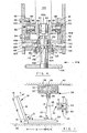
- the device is indicated by numeral 10A, the biasing means is denoted generally 24A and the adjusting means is denoted generally 26A.
- Lever system 12A pivots about a fulcrum 14A and includes output and input arms 18A and 20A with output arm 18A including an aperture 50 for securement thereto of a traction cord and harness.
- Webs 160 connect output and input arms 18A and 20A . and provide a mounting place for fulcrum 14A. Webs 160 are spaced apart to bracket input and output arms 18A, 20A and allow lever system 12A to pivot about fulcrum 14A without the need for a shaft member, coaxial with the pivot of fulcrum 14A, connecting webs 160 together.
- the strut 22A extends from the lower end of a piston 28A resident within a cylinder 30A extending downwardly from reservoir 34A.
- a housing 52 encloses reservoir 34A, cylinder 30A, strut 22A and arm 20A, with lever system 12A pivoting about fulcrum 14A providing a pivotal connection between lever 12A and housing 52.
- Arm 18A is exterior of housing 52.
- An opening 54 in housing wall 40 permits arm 18A to rotate about fulcrum 14A without interfering with the housing wall.
- Strut 22A rides on arm 20A via a roller 48A.
- Screw assembly 42A is secured in an extension tunnel 56 of housing 52.
- Screw assembly 42A includes a threaded shaft 58 extending inwardly through tunnel 56 towards strut 22A and includes a nut 59 secured to a handwheel 43A.
- Shaft 58 is pivotally connected to an ear 62 via an eye 64 formed at the end of shaft 58 by a cylindrical coupling 66 rotatably centrally received by eye 64 and an aperture central of ear 62. The aperture is not visible in Figure 2.
- check valve 68 Between cylinder 30A and reservoir 34A at the point of communication therebetween are a check valve 68 and a parallel bleed channel or passageway 70 connecting cylinder 30A to reservoir 34A for flow of first hydraulic fluid therebetween.
- Check valve 68 is shown schematically.
- Check valve 68 has a cross-sectional area for fluid flow, at the check valve seat when the check valve stem is spaced therefrom, substantially larger than the cross-sectional area of passageway 70.
- This arrangement of check valve 68 and passageway 70 permits unrestricted flow of hydraulic fluid from cylinder 30A to hydraulic fluid reservoir 34A while restricting flow in the reverse direction. Consequently, passageway 70 acts as a damper with respect to flow of hydraulic fluid between hydraulic reservoir 34A and cylinder 30A. This insures that should traction force suddenly be released due to, for example, breakage of the traction cord, piston 28A will move only slowly, thereby preventing violent motion of lever system 12A.
- a thrust bearing 60 is mounted in a bearing block 61 and held therein by a bearing cap plate 63. Thrust bearing 60 houses nut 59, permitting rotation of the latter about a common axis with threaded shaft 58.
- Bearing block 61 is pivotally connected to tunnel extension 56 with the pivot axis passing through thrust bearing 60 in a direction parallel to the axis of pivot 74.
- the pivotal mounting of bearing block 61 facilitates movement of rigid member 22A towards or away from fulcrum 1 4A in response to rotation of handwheel 43A.
- the pivotal mounting of bearing block 61 with respect to tunnel extension 56 is not shown in Figure 2.
- a roller pad 15 is secured to arm 20A by screws 161 to facilitate replacement in case of wear. Roller 48A rides on roller pad 15.
- roller 48A and pad 15 be configured so that the axis of roller 48A may be coaxially aligned with the axis of fulcrum 14A in the initial position.
- lever 12A, screw assembly 26A, rigid member 22A and biasing means 24A may be adjusted so that at the initial position the axis of roller 48A is coaxial with the axis of fulcrum 14A.
- roller 48A Alternate positions of roller 48A, illustrating the ability of roller 48A to move along lever input arm 20A, are shown in dotted lines in Figure 2. This is desirable to allow rotatable positioning of lever 12A, when initial force is applied by biasing means 24A, without the initial force changing as lever system 12A is rotated.
- An auxiliary nipple 72 extends laterally from cylinder 30A, allowing fluid to be introduced initially into cylinder 30A.
- Strut 22A extends axially from piston 28A and is rigidly secured thereto.
- Piston 28A is axially elongated so that independent movement of piston 28A, other than axially within cylinder 30A, is precluded.
- Cylinder 30A is rigidly secured to reservoir 34A and includes sealing means, not shown in Figure 2, in slideable contact with piston 28A to prevent escape of hydraulic fluid from cylinder 30A.
- Rigid member 22A and the biasing means including piston 28A, cylinder 30A and reservoir 34A are movable unitarily about a pivot 74 at which reservoir 34A is rotatably connected to housing 52.
- the structure of pivot 74 is preferably chosen so that reservoir 34A and the structural elements connected thereto are movable arcuately and only in a plane at least parallel with and preferably in common with that in which lever system 12A pivots about fulcrum 14A.
- E ar 62 via which threaded shaft 58 is connected to rigid member 22A, is affixed to a sleeve 76 fitted to and extending from cylinder 30A.
- Bearing means 78 provides structural connection between sleeve 76 and strut 22A while allowing relative motion of these two members with respect to one another in a direction parallel to the direction of relative movement between piston 28A and cylinder 30A.
- piston 28A, cylinder 30A and reservoir 34A moves arcuately about pivot 74, thereby altering the position at which roller 48A contacts arm 20A.
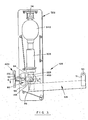
- the device is denoted generally 10B and includes a lever system 12B pivotable about a fulcrum 14B with a roller 48B journaling a strut 22B against lever system 12B.
- Strut 22B is connected to a piston, not shown, housed within a cylinder 30B fluidically connected to a reservoir 34B by a check valve and passageway combination equivalent to check valve 68 and passageway 70 in Figure 2.
- Reservoir 34B, cylinder 30B, the piston and strut 22B are unitarily arcuately movable about a pivot 74 connecting reservoir 34B to housing 52B.
- the lever system 12B has input and output arms combined into a single structure.
- Lever system 12B includes an aperture 50 formed in an ear 51 extending laterally from one end of lever 12B, with aperture 50 disposed to receive a traction cord and harness.
- An adjustable screw assembly 42B pivots about a third pivot 82 housed within a thrust block denoted generally 80 secured to the wall of housing 52B.
- Screw assembly 42B includes a clevis 96 (Fig.4) bracketing fork prongs 84 retaining roller 48B, for movement thereof by rotation of handle 106 of screw assembly 42B.
- Roller 48B is retained between two prongs 84 of an unnumbered fork formed at the end of strut 22B. Roller 48B rotates about a shaft, not shown / retained within conventional bearings held by prongs 84.
- Two drilled ears 86 are secured to lever 12B, preferably by welds, with the drilled holes aligned to define a common axis about which lever 12B rotates.
- bearing pins 88 (Fig.4) retained within inner annular races of bearing assemblies 90, which facilitate arcuate movement of lever 12B about fulcrum 14B defined by the inner annular races of bearing assemblies 90.
- Outer races of bearing assemblies 90 are retained in a bearing housing 92 secured to side walls 40B of housing 52B by bolts 94.
- Roller 48B is displaced along lever 12B by a clevis 96 having two prongs 98 bracketing prongs 84.
- the shaft on which roller 48B rotates may be journaled in bearings in both prongs 84 and in prongs 98 or may reside slideably in one pair of prongs, either prongs 84 or prongs 98, and be journaled in bearings retained in the remaining pair of prongs.
- clevis 96 Facingly abutting clevis 96 and extending outwardly therefrom is an enlarged shoulder portion 100 of a cylindrical shaft designated generally 102, where shaft 102 has a smaller, unnumbered portion fitted within clevis 96 and secured thereto. Extending outwardly from shoulder 100 away from clevis 96 is an externally threaded extension portion 104 of shaft 102.
- a handle 106 is fixedly connected to an internally threaded sleeve 108 with internal threads of sleeve 108 engaging external threads of extension 104.
- a flange 110 fixedly connected to sleeve 108 is retained between respective facing inner cylindrical races 112, 114 of bearing assemblies 11 6, 118.
- a hole 101 passes transversely through bearing block 80 in a direction substantially perpendicular to housing wall 40B.
- the axis of hole 101 preferably passes through, or close to, the axis of shaft 102.
- Pivot pins 128, which are interference fitted into hole 101, are respectively pressed into ends of hole 101, such that each pin 128 protrudes from thrust block 80 a distance approximately equal to the distance between faces 103 of bearing block 80 and the exterior, outwardly facing surfaces 150 of the adjacent housing wall 40 B .
- pivot pins 128 are rotatably mounted in bearings 105 retained within housing walls 40B.
- Flange 110 transfers any thrust load received by the screw assembly, resulting from reaction between roller 48B and lever 12B, to housing walls 40B via thrust bearings 116 and 118, thrust block 80, pivot pins 128 and pivot bearings 105.
- Rotation of handle 106 results in longitudinal displacement of shaft 102 and clevis 96, thereby moving roller 48B along lever 12B.
- Lever 12B is shown in Figure 3 in the preferred initial position at which rigid member 22B is perpendicular to a preferably planar portion of lever 12B on which roller 48B rides and the axes of roller 48B and pivot point 14B coincide. In this position the distance between roller 48B and fulcrum 14B is zero and, therefore, traction force exerted by lever 12B on the traction cord is zero, while screw assembly 42B may be rotated by handle 106 to produce the traction load.
- the axis of rotation of lever 12B about fulcrum 14B, the axis 82 of rotation of screw assembly 42B and the axis of rotation of rigid member 22B at pivot 74 are preferably parallel. This provides smooth, coplanar movement of the various parts of the invention as traction force is applied and varied.
- distance from the point at which roller 48 contacts input arm 20 to the point about which rigid member 22 rotates i.e. juncture of rigid member 22 and piston 26 in Figure 1 or pivot 74 in Figures 2 and 3, be large relative to allowable transverse displacement of roller 48 along input arm 20 as controlled by screw assembly 42.
- Such configuration results in little difficulty being encountered in turning screw 42 when lever 1 2 is in the preferred initial position because longitudinal movement of second rod 46 and hence transverse displacement of-roller 48 does not result in substantial longitudinal movement of rigid member 22 and hence little work need be input to reservoir 34 to move piston 28.
- roller 48 may be limited to about six centimeters of travel along arm 20 and the assembly of strut 22 and members connected thereto has a length about 45 centimeters from the point of contact of roller 48 with lever 12 to pivot 74.
- Nitrogen compressed to 80 atmospheres may be used as the compressible fluid in bladder 340
- An auxiliary rope and pulley system is preferably affixed to lever 12 to reposition lever 12 after the traction load is initially applied to the patient. This is desirable since upon initial application of the traction load, the harness worn by the patient may stretch or slip as the load is applied. This stretch or slip is taken up by movement of lever 12. Consequently if the apparatus is initially positioned with strut 22 substantially perpendicular to input arm 20, harness slip or stretch with consequent movement of lever 1 2 causes strut 22 to move away from the desired orientation perpendicular to lever 12.
- the auxiliary rope and pulley system facilitates return of the apparatus to the desired initial position before the physician, physiotherapist or patient begins to adjust traction force by rotating screw assembly 42. Manipulation of the auxiliary rope and pulley system also provides a convenient way of effecting intermittent application of the traction force. A suitable cleat is provided to secure the auxiliary rope at any preselected position.
- screw assembly 42 Besides providing means for varying the applied traction force, screw assembly 42 maintains strut 22 in an operator- selected position. This is desirable since, if operation begins with strut 22 perpendicular to input arm 20, once force P is applied and screw 42 is rotated to displace strut 22 and roller 48 along input arm 20, continued application of force P tends to continue to move roller 48 along input arm 20, further away from the initial position. Screw assembly 42 prevents this.
- the invention can for example be used to apply traction loads ranging from 1 to 100 kg. Travel of the portion of lever 12 to which the traction cord is affixed is normally limited to about 20 cm. Adjustable screw 42 permits the attending physician or physiotherapist to adjust traction force rapidly, thereby-facilitating application of a time varying traction force.
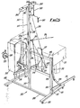
- a structure 210 is located at the foot of a couch 211 in readiness to apply lumbar traction to a patient recumbent on the couch.
- the structure 210 has a nominally vertical frame 212, a mast 213, and a traction applying cord 214 (shown as a line of spots) extending from a pulley block 215 on the mast.
- the cord connects to an attachment point 246 on a lever 221.
- Horizontal reaction members 216 provide ground reaction
- vertical reaction members 217 provide reaction at the foot of the couch.
- auxiliary cord 2 1 8 shown as a chain line
- pulley 220 is also attached to the lever 221 .
- the cord 218 extends from the end of lever 221 to a point 219 near the top of mast 213.
- the cord also passes over a pulley block 219a and is secured at a clamping cleat 219b.
- the auxiliary cord and pulley system allows the lever 221 to be lifted manually by an operator and thereby remove tension from the traction cords or lowered to apply tension. In this way traction can be applied with care and sensitivity as the cord creates a sensory link with the patient.
- the lever 221 extends from a mechanism 222 (as described above with reference to Figs. 1 to 4 or below with reference to Figures 6, 7 and 8) which applies variable and controllable load to the lever 221 as described below with reference to Figure 6.
- the mechanism 222 is secured to the frame 212 and has a load adjusting hand-wheel 223.
- the mast 213 is supported on a cross member 230 which is part of an I-shaped base 231 having parallel bars 232 mounted on castors 233 to render the structure mobile.
- Two verticals 234 form a part of the frame 212.
- the remainder of the frame being formed by cross-bars 235.
- the upper cross-bar 235 has a short strut 236 to the mast.
- the members 216 can pivot on pins 237 and have over-top-dead-centre cranks 238 to look the members 216 in the in-use position.
- the mast 213 has a number of hooks 239 so that the pulley block 215 can be set at various heights and thus alter the angle at which traction is applied to the patient.
- the mast 213 also includes means for applying cervical traction to a patient sitting in a chair.
- These means include an arm 240 on a pivot pin 241 at the top of the mast.
- the arm has one end 244 connected with a cord 245 (shown as a dash line) which couples to the lever 221 at a connector 247.
- the other end of the arm 240 has a connector 248 to which a cord 249 is fixed.
- the cord 249 supports a neck harness 243.
- the positions of attachment of cord 245 to the lever 221 and to the arm 240 are chosen to limit the cervical traction load to 14 kg. although this could be modified if essentially required.
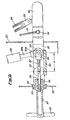
- FIG. 6 the inside of the mechanism 222 is shown.
- the lever 221 is forked and a pad 250 is provided between the arms of the fork.
- the lever is pivoted on a bearing 251 and is terminated at a collar 252 which supports a bearing 253.
- the bearing 253 has a boss 254 rotatable in it and the boss is extended by a tube 255 which terminates at the hand-wheel 223 (see also Fig 5).
- the boss has an internal nut 256 which engages a screw 257 terminating at a fork 258 which engages the shaft of a roller 259.
- the roller is carried on a fork 260a at the end of the piston rod 260b of a gas spring 260 and bears on the pad 250 and hence loads the lever 221.
- the hand-wheel is rotated and this moves the roller 259 along the pad and alters the distance "d", that is the distance at which the applied force of the gas spring acts from the pivot 251 of the lever 221.'
- the gas spring 260 could be disposed horizontally and the handle 225 disposed at the upper end of a vertical housing 261.
- the spring has a housing 222a pivoted at fulcrum 251.
- a single device provides for both lumbar and cervical traction exists.
- a minimum floor space is required and the device can be used with a standard couch or chair.
- the device can be wheeled away and stored, typically, in a floor space of 90 cms x 35 cms.
- the manual facility provided by cord 218 allows "feel" and easy application and removal of traction and allows application of intermittent traction. No electrical power is required. Portability poses no problems.
- the device In thoracic use, the device is wheeled to a couch foot, the legs 216 are lowered and locked.
- a pelvic harness on cord 214 is fitted to the patient and the pulley block 215 is located on an appropriate hook 239 to give the desired angle of traction.
- the lever 221 is then raised by pulling on the cord 218 and securing it raised by placing the cord in cleat 219b. Traction load is then selected at hand-wheel 223. Slack is removed from traction cord 214 and the cord is secured at an appropriate cleat (not shown).
- cord 218 is then released to apply traction load to the patient. There is "feel" by the operator as this occurs which arises from the tension in cord 218.
- Release from traction can be obtained by using cord 218 or releasing cord 214 from its cleat or by adjustment at hand-wheel 223.
Landscapes
- Health & Medical Sciences (AREA)
- Epidemiology (AREA)
- Pain & Pain Management (AREA)
- Physical Education & Sports Medicine (AREA)
- Rehabilitation Therapy (AREA)
- Life Sciences & Earth Sciences (AREA)
- Animal Behavior & Ethology (AREA)
- General Health & Medical Sciences (AREA)
- Public Health (AREA)
- Veterinary Medicine (AREA)
- Orthopedics, Nursing, And Contraception (AREA)
Applications Claiming Priority (4)
| Application Number | Priority Date | Filing Date | Title |
|---|---|---|---|
| US06/268,129 US4429692A (en) | 1981-05-29 | 1981-05-29 | Traction force adjustment apparatus |
| GB8204640 | 1982-02-17 | ||
| GB8204640 | 1982-02-17 | ||
| US268129 | 1994-07-06 |
Publications (2)
| Publication Number | Publication Date |
|---|---|
| EP0066450A2 true EP0066450A2 (fr) | 1982-12-08 |
| EP0066450A3 EP0066450A3 (fr) | 1983-02-16 |
Family
ID=26281998
Family Applications (1)
| Application Number | Title | Priority Date | Filing Date |
|---|---|---|---|
| EP82302694A Withdrawn EP0066450A3 (fr) | 1981-05-29 | 1982-05-26 | Appareil pour appliquer des forces de traction à un patient |
Country Status (1)
| Country | Link |
|---|---|
| EP (1) | EP0066450A3 (fr) |
Family Cites Families (5)
| Publication number | Priority date | Publication date | Assignee | Title |
|---|---|---|---|---|
| US3134379A (en) * | 1962-09-10 | 1964-05-26 | Frank J Nightingale | Portable bed type traction applicator |
| US3654922A (en) * | 1970-07-10 | 1972-04-11 | Dale E Outcalt | Door mounted cervical variable weight traction unit |
| US3699953A (en) * | 1970-09-16 | 1972-10-24 | Virginia S Mason | Self-operating traction system |
| SE389267B (sv) * | 1973-06-13 | 1976-11-01 | O Wallander | Anordning for att astadkomma en vesentligen konstant, instellbar kraft i en anbringningspunkt medelst en streckanordning, spec. for kirurgisk streckbehandling |
| US3868951A (en) * | 1973-09-07 | 1975-03-04 | Donald Albrecht | Traction device |
-
1982
- 1982-05-26 EP EP82302694A patent/EP0066450A3/fr not_active Withdrawn
Also Published As
| Publication number | Publication date |
|---|---|
| EP0066450A3 (fr) | 1983-02-16 |
Similar Documents
| Publication | Publication Date | Title |
|---|---|---|
| US4664101A (en) | Open frame traction system | |
| US5114389A (en) | Stair climber exercise device | |
| US6035465A (en) | Patient lifting and support system | |
| US4550908A (en) | Physical-rehabilitation and exercising apparatus | |
| US5372561A (en) | Apparatus for suspension assisted ambulation | |
| US4726358A (en) | Manipulative treatment device having pivoting links between base and supports | |
| US20170252602A1 (en) | Supportive exercise machine | |
| KR100413224B1 (ko) | 제어장치 및 이를 이용한 허리 재활운동시스템 | |
| US5545177A (en) | Apparatus for applying acupressure | |
| US6984217B2 (en) | Cervical distraction device | |
| US6503176B2 (en) | Walker device with power assisted lift | |
| US5848984A (en) | Apparatus for relieving back pain | |
| US6676574B1 (en) | Shift position selector for a pad on an exercise machine | |
| US3868951A (en) | Traction device | |
| US4700696A (en) | Method and apparatus for applying traction | |
| US4690133A (en) | Inversion apparatus | |
| US5002043A (en) | Inversion apparatus | |
| US5954750A (en) | Drop mechanism for chiropractic table | |
| US5022388A (en) | Patient table apparatus | |
| US4809685A (en) | Chiropractic table lever-locking mechanism | |
| US3205887A (en) | Apparatus for producing massage | |
| US5895367A (en) | Medical therapeutic device for placing a patient into either traction or compression | |
| JPH11235253A (ja) | 寝台の側柵 | |
| JPH0779823B2 (ja) | 多機能牽引ベッド | |
| CN212395746U (zh) | 下肢康复训练机器人变形总成 |
Legal Events
| Date | Code | Title | Description |
|---|---|---|---|
| PUAI | Public reference made under article 153(3) epc to a published international application that has entered the european phase |
Free format text: ORIGINAL CODE: 0009012 |
|
| AK | Designated contracting states |
Designated state(s): CH DE FR GB NL SE |
|
| PUAL | Search report despatched |
Free format text: ORIGINAL CODE: 0009013 |
|
| AK | Designated contracting states |
Designated state(s): CH DE FR GB LI NL SE |
|
| STAA | Information on the status of an ep patent application or granted ep patent |
Free format text: STATUS: THE APPLICATION IS DEEMED TO BE WITHDRAWN |
|
| 18D | Application deemed to be withdrawn |
Effective date: 19840130 |