EP0066739A2 - Mécanisme de changement de vitesse d'une transmission de véhicule à commande manuelle - Google Patents
Mécanisme de changement de vitesse d'une transmission de véhicule à commande manuelle Download PDFInfo
- Publication number
- EP0066739A2 EP0066739A2 EP82104329A EP82104329A EP0066739A2 EP 0066739 A2 EP0066739 A2 EP 0066739A2 EP 82104329 A EP82104329 A EP 82104329A EP 82104329 A EP82104329 A EP 82104329A EP 0066739 A2 EP0066739 A2 EP 0066739A2
- Authority
- EP
- European Patent Office
- Prior art keywords
- lever
- gear
- axis
- operating
- guide pin
- Prior art date
- Legal status (The legal status is an assumption and is not a legal conclusion. Google has not performed a legal analysis and makes no representation as to the accuracy of the status listed.)
- Granted
Links
Images

Classifications
-
- F—MECHANICAL ENGINEERING; LIGHTING; HEATING; WEAPONS; BLASTING
- F16—ENGINEERING ELEMENTS AND UNITS; GENERAL MEASURES FOR PRODUCING AND MAINTAINING EFFECTIVE FUNCTIONING OF MACHINES OR INSTALLATIONS; THERMAL INSULATION IN GENERAL
- F16H—GEARING
- F16H63/00—Control outputs from the control unit to change-speed- or reversing-gearings for conveying rotary motion or to other devices than the final output mechanism
- F16H63/02—Final output mechanisms therefor; Actuating means for the final output mechanisms
- F16H63/30—Constructional features of the final output mechanisms
- F16H63/34—Locking or disabling mechanisms
- F16H63/36—Interlocking devices
-
- F—MECHANICAL ENGINEERING; LIGHTING; HEATING; WEAPONS; BLASTING
- F16—ENGINEERING ELEMENTS AND UNITS; GENERAL MEASURES FOR PRODUCING AND MAINTAINING EFFECTIVE FUNCTIONING OF MACHINES OR INSTALLATIONS; THERMAL INSULATION IN GENERAL
- F16H—GEARING
- F16H63/00—Control outputs from the control unit to change-speed- or reversing-gearings for conveying rotary motion or to other devices than the final output mechanism
- F16H63/02—Final output mechanisms therefor; Actuating means for the final output mechanisms
- F16H63/30—Constructional features of the final output mechanisms
- F16H63/302—Final output mechanisms for reversing
-
- Y—GENERAL TAGGING OF NEW TECHNOLOGICAL DEVELOPMENTS; GENERAL TAGGING OF CROSS-SECTIONAL TECHNOLOGIES SPANNING OVER SEVERAL SECTIONS OF THE IPC; TECHNICAL SUBJECTS COVERED BY FORMER USPC CROSS-REFERENCE ART COLLECTIONS [XRACs] AND DIGESTS
- Y10—TECHNICAL SUBJECTS COVERED BY FORMER USPC
- Y10T—TECHNICAL SUBJECTS COVERED BY FORMER US CLASSIFICATION
- Y10T74/00—Machine element or mechanism
- Y10T74/20—Control lever and linkage systems
- Y10T74/20012—Multiple controlled elements
- Y10T74/20018—Transmission control
- Y10T74/20085—Restriction of shift, gear selection, or gear engagement
- Y10T74/20104—Shift element interlock
- Y10T74/2011—Shift element interlock with detent, recess, notch, or groove
Definitions
- the present invention relates in general to an automotive selected gear sliding type manual transmission, and more particularly to a gear operating mechanism of the transmission, which has means for positively preventing the undesirable gear disengagement phenomenon.
- gear disengagement In a manual transmission of a selected gear sliding type, a so-called “gear disengagement” sometimes happens particularly in a long-used transmission.
- the gear disengagement is an undesirable phenomenon in which the gear assuming its operating or engaged position is suddenly and unexpectedly disengages from the associated gears thereby suddenly breaking the power transmitting connection between the engine and the driven road wheels.
- various measures have been hitherto proposed. However, some of them have been made at the sacrifice of handling comfortableness and production cost of the transmission.
- a gear operating mechanism in a selected gear sliding type manual transmission having a gear which is axially slidable from its neutral position where it disengages from the associated gears to its operating position where it engages with the associated gears, a gear operating mechanism.
- the gear operating mechanism comprises a first lever pivotally movable about a first axis relative to a case of the transmission to move the gear between the neutral position and the operating position; a second lever pivotally movable about a second axis relative to the transmission case, the second axis being parallel with the first axis; first means for providing a cam-connection between the first lever and the second lever in such a manner that the pivotal movement of the second lever about the second axis within a predetermined angular range induces through the first lever the movement of the gear between the neutral and operating positions; and second means for pivotally moving the second lever about the second axis in response to the movement of a speed change shift lever of the transmission, wherein the first lever, the second lever and the first means are so arranged and constructed that when, with the gear assuming the operating position, a force is applied to the gear to urge the same in a direction from the operating position to the neutral position, at least a part of the force is received by the transmission case through the first lever, the second lever and the
- the present invention is not limited to such reverse gear operating mechanism, but applicable widely to any mechanism so long as it includes an axially slidable gear for effecting a predetermined gear ratio.
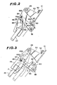
- Figs. 1 and 2 there is shown a part of an automotive manual transmission, where a reverse gear operating mechanism according to the present invention is arranged.
- a coupling sleeve of a fifth speed synchronizing clutch mechanism is mounted about the input shaft 12 for smoothly connecting a fifth speed input gear (which is journalled on the input shaft 12 and constantly meshed with a fifth speed output gear securely mounted on the output shaft 14) to the input shaft 12 thereby to smoothly establish the fifth speed gear ratio.
- a reverse input gear 18 is securely mounted on the input shaft 12 to rotate therewith, while, a reverse output gear 20 is secured to the output shaft 14 at a position near the reverse input gear .18.
- a reverse idler gear 22 is rotatably and axially slidably disposed on a stationary shaft 24 which extends parallel with the input and output shafts 12 and 14.
- the reverse idler gear 22 is movable on the shaft 24 from an operating position where it meshes with both the reverse input gear 18 and the reverse output gear 20 to an inoperative or neutral position where it disengages from them.
- the reverse input gear 18 and the reverse output gear 20 rotate together to effect the reverse condition of the transmission.
- Denoted by numeral 26 is a fork shaft which extends parallel with the input and output shafts 12 and 14 and is secured to the transmission case 10.
- a shift fork 28 is axially slidably mounted at its hub section on the fork shaft 26.
- the shift fork 28 has at its one end a bifurcated arm portion 28a which holds the coupling sleeve 16.
- the shift fork 28 is formed with an arm portion 28b which extends from the hub section thereof in a direction opposite to the bifurcated arm portion 28a.
- the leading end of the arm portion 28b is formed with a recess 30 into which a portion of the next-mentioned pivoting lever 32 is insertable.
- the pivoting lever 32 has two arms 32a and 32b which extend in opposite directions from the hub section thereof.
- the pivoting lever 32 is rotatably and axially slidably disposed on a stationary shaft 34 which extends parallel with the input and output shafts 12 and 14.
- the leading end of the arm 32a is inserted into the recess 30 of the shift fork arm portion 28b to engage therewith when the pivoting lever 32 assumes a predetermined angular position relative to the shaft 34.
- the other arm 32b of the pivoting lever 32 is formed with a blind hole 36.
- a spherical head portion 38a of a speed change arm 38 Slidably received in the blind hole 36 of the pivoting lever 32 is a spherical head portion 38a of a speed change arm 38.
- the speed change arm 38 is rotatably and axially slidably disposed at is hub section on a stationary rod 40 which extends perpendicular to the shaft 34.
- First and second springs 42 and 44 are mounted about the rod 40 to put therebetween the hub section of the speed change arm 38 so that the arm 38 is resiliently and balancedly held in an axial position.
- an operating or first lever 46 in order to axially move the idler gear 22 on the shaft 24.
- One end of the operating lever 46 is pivotally connected through a pivoting pin 48 to a bracket 50 which is secured to the transmission case 10 by bolts 52 and 54, so that the operating lever 46 is movable over a flat plane which is parallel with the axis of the idler gear shaft 24.
- the other end of the operating lever 46 is forked into two arm portions which straddle the idler gear 22 to hold the same, as is understood from Figs. 2 and 3.
- a handling or second lever 56 which lies near the operating lever 46.
- the base portion of the handling lever 56 is pivotally connected through a pivoting shaft 58 to the transmission case 10, so that the handling lever 56 is movable over a flat plane which is parallel with another flat plane over which the operating lever 46 is movable.
- the handling lever 56 is formed near the base portion thereof with a L-shaped slot 60 which consists of first and second straight sections 60a and 60b which intersect at right angles.
- a guide pin 62 secured to the arm portion 28b of the shift fork 28 is slidably received in the slot 60.
- the handling lever 56 can assume a position where when the shift fork 28 moves in a direction to cause the coupling sleeve 16 to move from the neutral position to its operating or engaged position to establish the fifth speed gear ratio, the pin 62 on the shift fork 28 moves in the first straight section 60a of the slot 60 in the direction of the arrow A, that is, from the position indicated by the solid line to the position indicated by a phantom line in Fig.
- the handling lever 56 is provided at its leading end with a guide pin 64 secured thereto which is slidably received in a slot 66 formed in the operating lever 46.
- the slot 66 consists of a main straight section 66a, and first and second end sections 66b.and 66c which extend in the opposite directions from opposed ends of the main straight section 66a. As shown, the sections 66b and 66c are inclined with respect to the main straight section 66a.
- the slot 66 is so formed that when the handling lever 56 assumes the position as shown in Fig.
- the pin 64 contacts with the bottom of the first end section 66b, and at this time, the first and second end sections 66b and 66c are arranged to extend tangentially with respect to respective circles of which centers lie on the axis of the pivoting shaft 58.
- the above-stated counterclockwise rotation of the handling lever 56 induces a clockwise rotation of the operating lever 46 about the pivoting pin 48 in Fig. 2, forcing the guide pin 64 to move in and along the slot 66 toward the second end section 66c.
- the speed change arm 38 (see Fig. 1) is moved on and along the rod 40 in a direction to cause the leading end of the pivoting lever arm 32a to engage with the recess 30 of the shift fork arm portion 28b.
- the speed change arm 38 is rotated about the rod 40 in a direction to cause the shift fork 28 to axially slide on the fork shaft 26 in a given direction. With this movement, the coupling sleeve 16 comes to its operating position to establish the fifth forward gear ratio.
- the guide pin 62 secured to the shift fork 28 is moved in the direction of the arrow A from a position indicated by the solid line in Fig. 2 to another position indicated by a phantom line in the drawing.
- such movement of the guide pin 62 does not induce any movement of the handling lever 56 about the pivoting shaft 58, so that the operating lever 46 is stationarily held in the position shown in Fig. 2.
- the idler gear 22 keeps its neutral position which is indicated by a phantom line in Fig. 3.
- the speed change arm 38 is rotated about the rod 40 in the opposite direction causing the shift fork 28 to move the coupling sleeve 16 to its inoperative position.
- the guide pin 62 secured to the shift fork ' 28 is moved in the direction of the arrow B and thus rotates the handling lever 56 about the pivoting shaft 58 in the counterclockwise direction in Fig. 2.
- the operating lever 46 come to.the position indicated by a solid line in Fig. 3 shifting the idler gear 22 from the inoperative position indicated by the phantom line in Fig. 3 to the operating position indicated by a solid line in the drawing.
- the reverse condition is established in the transmission.
- the parts may be so arranged that when the idler gear 22 assumes its operating position, a straight line X which perpendicularly intersects both the axes of the pivoting shaft 58 and the guide pin 64 is perpendicular to another straight line Y which perpendicularly intersects both the axes of pivoting pin 48 and the guide pin 64. According to this construction, almost all of the force F is received by the transmission case 10 through the linked parts thereby improving the gear disengagement preventing phenomenon much more effectively.
Landscapes
- Engineering & Computer Science (AREA)
- General Engineering & Computer Science (AREA)
- Mechanical Engineering (AREA)
- Gear-Shifting Mechanisms (AREA)
- Control Of Transmission Device (AREA)
Applications Claiming Priority (2)
| Application Number | Priority Date | Filing Date | Title |
|---|---|---|---|
| JP56074099A JPS57190162A (en) | 1981-05-19 | 1981-05-19 | Preventive mechanism of gear disengagement |
| JP74099/81 | 1981-05-19 |
Publications (3)
| Publication Number | Publication Date |
|---|---|
| EP0066739A2 true EP0066739A2 (fr) | 1982-12-15 |
| EP0066739A3 EP0066739A3 (en) | 1983-10-05 |
| EP0066739B1 EP0066739B1 (fr) | 1987-08-26 |
Family
ID=13537393
Family Applications (1)
| Application Number | Title | Priority Date | Filing Date |
|---|---|---|---|
| EP82104329A Expired EP0066739B1 (fr) | 1981-05-19 | 1982-05-17 | Mécanisme de changement de vitesse d'une transmission de véhicule à commande manuelle |
Country Status (4)
| Country | Link |
|---|---|
| US (1) | US4497216A (fr) |
| EP (1) | EP0066739B1 (fr) |
| JP (1) | JPS57190162A (fr) |
| DE (1) | DE3277092D1 (fr) |
Families Citing this family (4)
| Publication number | Priority date | Publication date | Assignee | Title |
|---|---|---|---|---|
| JP2522793B2 (ja) * | 1987-05-08 | 1996-08-07 | 日産自動車株式会社 | 変速機の変速操作機構 |
| DE19605980C2 (de) * | 1996-02-17 | 1998-02-26 | Ford Werke Ag | Schaltvorrichtung für Wechselgetriebe, insbesondere für Kraftfahrzeuge |
| EP2711592B1 (fr) * | 2012-09-21 | 2015-05-27 | C.R.F. Società Consortile per Azioni | Dispositif pour la sélection et l'engagement des vitesses d'une boîte de vitesses pour véhicules à moteur |
| US9347549B2 (en) | 2013-03-20 | 2016-05-24 | Gm Global Technology Operations, Llc | Gear engagement mechanism |
Family Cites Families (16)
| Publication number | Priority date | Publication date | Assignee | Title |
|---|---|---|---|---|
| US1089186A (en) * | 1912-06-14 | 1914-03-03 | Aloysius B Brockman | Transmission mechanism. |
| US1209782A (en) * | 1914-09-28 | 1916-12-26 | William E Tullar | Controlling means for motor-driven vehicles. |
| US1685502A (en) * | 1925-02-09 | 1928-09-25 | Twin Disc Clutch Co | Clutch and transmission mechanism |
| GB688842A (en) * | 1950-03-23 | 1953-03-18 | Vauxhall Motors Ltd | Improved control mechanism for change-speed gearing |
| US2798382A (en) * | 1955-04-04 | 1957-07-09 | Dana Corp | Power take-off control mechanism |
| GB841985A (en) * | 1957-06-18 | 1960-07-20 | Engineering Res & Applic Ltd | Improvements in or relating to power transmission means and means for effecting change of ratio |
| US3241640A (en) * | 1963-07-03 | 1966-03-22 | Chrysler Corp | Control linkage arrangement |
| JPS4419691Y1 (fr) * | 1965-11-06 | 1969-08-23 | ||
| US3461739A (en) * | 1967-04-25 | 1969-08-19 | George J Viegas | Gear shift mechanism |
| US3500697A (en) * | 1968-08-29 | 1970-03-17 | Case Co J I | Shifting device for transmission |
| GB1432345A (en) * | 1972-04-13 | 1976-04-14 | Smith Enphew Research Ltd | Ophthalmic compositions and contact lens disinfecting compo sitions |
| JPS562624B2 (fr) * | 1975-01-31 | 1981-01-21 | ||
| US4277983A (en) * | 1978-09-04 | 1981-07-14 | Honda Giken Kogyo Kabushiki Kaisha | Interlocking device for shift rod in power transmission |
| US4228693A (en) * | 1978-12-11 | 1980-10-21 | Borg-Warner Corporation | Transmission shift control apparatus |
| US4337675A (en) * | 1980-05-27 | 1982-07-06 | Borg-Warner Corporation | Transmission shift control apparatus |
| US4370897A (en) * | 1980-09-22 | 1983-02-01 | American Industries, Inc. | Dual mode shifter for automatic transmissions |
-
1981
- 1981-05-19 JP JP56074099A patent/JPS57190162A/ja active Granted
-
1982
- 1982-05-17 DE DE8282104329T patent/DE3277092D1/de not_active Expired
- 1982-05-17 EP EP82104329A patent/EP0066739B1/fr not_active Expired
- 1982-05-18 US US06/379,510 patent/US4497216A/en not_active Expired - Fee Related
Also Published As
| Publication number | Publication date |
|---|---|
| US4497216A (en) | 1985-02-05 |
| DE3277092D1 (en) | 1987-10-01 |
| EP0066739A3 (en) | 1983-10-05 |
| JPH0413579B2 (fr) | 1992-03-10 |
| EP0066739B1 (fr) | 1987-08-26 |
| JPS57190162A (en) | 1982-11-22 |
Similar Documents
| Publication | Publication Date | Title |
|---|---|---|
| US4193316A (en) | Transmission shift control mechanism | |
| CA1259823A (fr) | Transmission pour vehicule | |
| US4472868A (en) | Method of assembling an automotive manual transmission | |
| EP0058965B1 (fr) | Boîte de vitesses ayant un levier à main | |
| EP0066739A2 (fr) | Mécanisme de changement de vitesse d'une transmission de véhicule à commande manuelle | |
| US4126055A (en) | Transmission reverse interlock | |
| EP0066178B1 (fr) | Mécanisme de changement de vitesse d'une transmission de véhicule à commande manuelle | |
| EP0139261B1 (fr) | Mécanisme de commande d'une boîte de changement de vitesses manuelle pour un véhicule | |
| CN216009401U (zh) | 车辆变速器系统中的致动系统 | |
| US4827792A (en) | Transmission shift control mechanism | |
| EP0058969B1 (fr) | Transmission de véhicule à commande manuelle | |
| US4539858A (en) | Shift control mechanism of an automotive manual transmission | |
| CA1174942A (fr) | Mecanisme de passage des vitesses d'une transmission | |
| US5203225A (en) | Vehicle transmission gearshift for preventing accidental engagement | |
| EP0058963A2 (fr) | Mécanisme de commande d'une boîte de changement de vitesses manuelle pour un véhicule | |
| US4648283A (en) | Gear shift control mechanism | |
| US4449418A (en) | Gearshift device | |
| GB2108602A (en) | Control device for the auxiliary gear reducing unit of a motor vehicle having four driving wheels | |
| EP0066738A2 (fr) | Mécanisme de changement de vitesses d'une transmission de véhicule à commande manuelle | |
| US4520685A (en) | Shift control mechanism of an automotive manual transmission | |
| JPS624020Y2 (fr) | ||
| JPS6233161Y2 (fr) | ||
| JPS5828260Y2 (ja) | 変速操作装置におけるミスシフト防止機構 | |
| JPH0828702A (ja) | 歯車式変速機のリバース操作機構 | |
| JPH0219656Y2 (fr) |
Legal Events
| Date | Code | Title | Description |
|---|---|---|---|
| PUAI | Public reference made under article 153(3) epc to a published international application that has entered the european phase |
Free format text: ORIGINAL CODE: 0009012 |
|
| AK | Designated contracting states |
Designated state(s): DE FR GB |
|
| PUAL | Search report despatched |
Free format text: ORIGINAL CODE: 0009013 |
|
| AK | Designated contracting states |
Designated state(s): DE FR GB |
|
| 17P | Request for examination filed |
Effective date: 19820517 |
|
| RAP1 | Party data changed (applicant data changed or rights of an application transferred) |
Owner name: NISSAN MOTOR CO., LTD. |
|
| GRAA | (expected) grant |
Free format text: ORIGINAL CODE: 0009210 |
|
| AK | Designated contracting states |
Kind code of ref document: B1 Designated state(s): DE FR GB |
|
| PG25 | Lapsed in a contracting state [announced via postgrant information from national office to epo] |
Ref country code: FR Free format text: THE PATENT HAS BEEN ANNULLED BY A DECISION OF A NATIONAL AUTHORITY Effective date: 19870826 |
|
| REF | Corresponds to: |
Ref document number: 3277092 Country of ref document: DE Date of ref document: 19871001 |
|
| EN | Fr: translation not filed | ||
| PLBE | No opposition filed within time limit |
Free format text: ORIGINAL CODE: 0009261 |
|
| STAA | Information on the status of an ep patent application or granted ep patent |
Free format text: STATUS: NO OPPOSITION FILED WITHIN TIME LIMIT |
|
| 26N | No opposition filed | ||
| PGFP | Annual fee paid to national office [announced via postgrant information from national office to epo] |
Ref country code: GB Payment date: 19960508 Year of fee payment: 15 |
|
| PGFP | Annual fee paid to national office [announced via postgrant information from national office to epo] |
Ref country code: DE Payment date: 19960528 Year of fee payment: 15 |
|
| PG25 | Lapsed in a contracting state [announced via postgrant information from national office to epo] |
Ref country code: GB Effective date: 19970517 |
|
| GBPC | Gb: european patent ceased through non-payment of renewal fee |
Effective date: 19970517 |
|
| PG25 | Lapsed in a contracting state [announced via postgrant information from national office to epo] |
Ref country code: DE Free format text: LAPSE BECAUSE OF NON-PAYMENT OF DUE FEES Effective date: 19980203 |