EP0066807A1 - Outil de perçage - Google Patents
Outil de perçage Download PDFInfo
- Publication number
- EP0066807A1 EP0066807A1 EP82104708A EP82104708A EP0066807A1 EP 0066807 A1 EP0066807 A1 EP 0066807A1 EP 82104708 A EP82104708 A EP 82104708A EP 82104708 A EP82104708 A EP 82104708A EP 0066807 A1 EP0066807 A1 EP 0066807A1
- Authority
- EP
- European Patent Office
- Prior art keywords
- cutting
- drilling tool
- cutting edges
- edge
- face
- Prior art date
- Legal status (The legal status is an assumption and is not a legal conclusion. Google has not performed a legal analysis and makes no representation as to the accuracy of the status listed.)
- Granted
Links
- 238000005553 drilling Methods 0.000 title claims abstract description 12
- 241001531957 Opsariichthys uncirostris Species 0.000 claims description 3
- 230000035515 penetration Effects 0.000 description 2
- 238000003754 machining Methods 0.000 description 1
- 238000000034 method Methods 0.000 description 1
- 238000004080 punching Methods 0.000 description 1
- 238000010079 rubber tapping Methods 0.000 description 1
Images

Classifications
-
- B—PERFORMING OPERATIONS; TRANSPORTING
- B23—MACHINE TOOLS; METAL-WORKING NOT OTHERWISE PROVIDED FOR
- B23B—TURNING; BORING
- B23B51/00—Tools for drilling machines
- B23B51/02—Twist drills
-
- B—PERFORMING OPERATIONS; TRANSPORTING
- B23—MACHINE TOOLS; METAL-WORKING NOT OTHERWISE PROVIDED FOR
- B23B—TURNING; BORING
- B23B2251/00—Details of tools for drilling machines
- B23B2251/18—Configuration of the drill point
-
- B—PERFORMING OPERATIONS; TRANSPORTING
- B23—MACHINE TOOLS; METAL-WORKING NOT OTHERWISE PROVIDED FOR
- B23B—TURNING; BORING
- B23B2251/00—Details of tools for drilling machines
- B23B2251/20—Number of cutting edges
- B23B2251/202—Three cutting edges
-
- B—PERFORMING OPERATIONS; TRANSPORTING
- B23—MACHINE TOOLS; METAL-WORKING NOT OTHERWISE PROVIDED FOR
- B23B—TURNING; BORING
- B23B2251/00—Details of tools for drilling machines
- B23B2251/24—Overall form of drilling tools
- B23B2251/241—Cross sections of the diameter of the drill
Definitions
- This operating mode constitutes a heavy constraint in machining on an automatic machine and in particular of the numerically controlled type, in that it does not make it possible to obtain the best desirable yield.
- the subject of the present invention is an embodiment of a drilling tool making it possible to ensure both the pointing, drilling and boring functions in a single pass and which, for this purpose, is essentially characterized in that it comprises at least three flutes leaving between them three lips ending in a point with cutting edges which concur at its top.
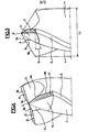
- the drilling tool shown comprises a body 1 and a shank 2 which can be adapted to any known method of attachment, the body being here formed with three helical flutes 3 forming between them three lips 4, which are diametrically delimited by cylindrical strips 5 and also shaped in a manner known per se as can be seen in FIG. 2.
- the core 6 of this tool is chosen to be of such a diameter with respect to the nominal diameter of the tool that the flutes can make it possible to obtain good clearance of chips, this ratio possibly being between 15 and 30 % depending on the material to be drilled and that of the tool, with a marked preference between 20 and 25% in general.
- the tool has a point with cutting edges 8 which compete at the top 9 of the point and which has the chosen penetration cone as its envelope.
- Each edge comprises a central part 8a delimited by a notch formed in the core of the tool so as to form the cutting face 10 of this part 8a of the edge at the same time as a chip chamber opening onto the corresponding flute.
- the orientation of the cutting face 10 can be chosen to give rise to a zero or slightly positive or negative cutting angle 11.
- Part 8b of each cutting edge, also delimited on each lip according to the chosen penetration cone is followed behind the cutting direction, as well as part 8a, by a draft face 12 inclined by a draft angle 13, and the rear edge of which extends along a radius from the corner point to the apex smaller than that of the cutting edges 8.
- the relief faces 12 can be provided especially flat or curved profile.
- Each undercut face is followed by an undercut face 14, which can be formed by notching the core and the corresponding lip at the same time as the cutting face 10, and which contributes to opening the chip chamber opening into the corresponding flute.
- the flutes may not necessarily be helical but could possibly be axial depending on the application envisaged for such a tool.
Landscapes
- Engineering & Computer Science (AREA)
- Mechanical Engineering (AREA)
- Drilling Tools (AREA)
Abstract
Description
- Avec les forets classiques à deux goujures et arête principale coupante, il est pratiquement nécessaire d'utiliser un foret à centrer afin de bien positionner le trou à percer (pointage), puis après le perçage avec foret classique, d'utiliser un alésoir à arêtes coupantes multiples en chanfrein destinée à redresser éventuellement le trou, à assurer son diamètre dans les tolérances exigées et à améliorer son état de surface (notamment lorsque l'opération doit être suivie d'un taraudage précis).
- Ce mode opératoire constitue une servitude pesante dans les usinages sur machine automatique et notamment du type à commande numérique, en ce qu'il ne permet pas d'en obtenir le meilleur rendement désirable.
- La présente invention a pour objet une réalisation d'outil de perçage permettant d'assurer à la fois les fonctions de pointage, perçage et alésage en une seule passe et qui, à cet effet, est essentiellement caractérisé en ce qu'il comprend au moins trois goujures ménageant entre elles trois lèvres se terminant par une pointe à arêtes coupantes concourantes à son sommet. On comprendra que la présence d'au moins trois arêtes coupantes concourantes au sommet de la pointe permet à un tel outil de remplir l'office de pointeau et de jouir d'un bon positionnement à l'attaque simultanée du perçage, de même qu'il est mieux guidé et plus rigide qu'un foret à deux goujures et qu'on peut lui donner une âme suffisante pour permettre aux goujures d'assurer un bon dégagement de copeaux tout en étant moindre que celle des alésoirs, dont il se distingue également par sa pointe à arêtes coupantes concourantes, ce qui lui permet ainsi de remplir à lui seul les trois fonctions évoquées.
- D'autres particularités d'un outil de perçage selon l'invention apparaîtront d'ailleurs dans la description suivante d'une forme de réalisation d'un tel outil, représentée à titre d'exemple seulement au dessin annexé, dans lequel :
- la fig. 1 est une vue extérieure d'un tel outil de perçage;
- la fig. 2 est une vue en coupe suivant II-II de la fig. 1;
- la fig. 3 est une vue en élévation de la pointe d'un tel outil;
- la fig. 4 est une vue en perspective de dessus de la pointe de l'outil destinée à faire apparaître l'ensemble de ses arêtes coupantes.
- L'outil de perçage représenté comprend un corps 1 et une queue 2 pouvant être adaptée à tout mode de fixation connu, le corps étant ici formé avec trois goujures hélicoïdales 3 ménageant entre elles trois lèvres 4, qui sont diamétralement délimitées par des listels cylindriques 5 et par ailleurs conformées de manière connue en soi comme on le voit bien à la fig. 2. L'âme 6 de cet outil est choisie d'un diamètre tel par rapport au diamètre nominal de l'outil que les goujures peuvent permettre l'obtention d'un bon dégagement de copeaux, ce rapport pouvant être compris entre 15 et 30% selon la matière à percer et celle de l'outil, avec une préférence marquée entre 20 et 25% de façon générale.
- Comme illustré aux fig. 3 et 4, l'outil présente une pointe à arêtes coupantes 8 concourantes au sommet 9 de la pointe et ayant pour enveloppe le cône de pénétration choisi. Chaque arête comprend une partie centrale 8a délimitée par une entaille ménagée dans l'âme de l'outil de façon à former la face de coupe 10 de cette partie 8a de l'arête en même temps qu'une chambre à copeaux s'ouvrant sur la goujure correspondante. L'orientation de la face de coupe 10 peut être choisie pour donner lieu à un angle de coupe 11 nul ou légèrement positif ou négatif. La partie 8b de chaque arête coupante, également délimitée sur chaque lèvre suivant le cône de pénétration choisi est suivie en arrière du sens de coupe, ainsi que la partie 8a, par une face de dépouille 12 inclinée d'un angle de dépouille 13, et dont l'arête arrière s'étend suivant un rayon de la pointe d'angle au sommet inférieur à celui des arêtes coupantes 8. Les faces de dépouille 12 peuvent être prévues planes ou de profil courbe notamment. Chaque face de dépouille est suivie d'une face de contre-dépouille 14, qui peut être formée par entaillage de l'âme et de la lèvre correspondante en même temps que la face de coupe 10, et qui contribue à ouvrir la chambre à copeaux débouchant dans la goujure correspondante.
- Bien entendu diverses variantes de détail peuvent être imaginées dans le cadre de l'invention, étant à voir notamment que les goujures peuvent ne pas être forcément hélicoïdales mais pourraient éventuellement être axiales selon l'application envisagée pour un tel outil.
Claims (3)
Applications Claiming Priority (2)
| Application Number | Priority Date | Filing Date | Title |
|---|---|---|---|
| FR8111109 | 1981-06-04 | ||
| FR8111109A FR2507115A1 (fr) | 1981-06-04 | 1981-06-04 | Outil de percage comprenant au moins trois goujures |
Publications (2)
| Publication Number | Publication Date |
|---|---|
| EP0066807A1 true EP0066807A1 (fr) | 1982-12-15 |
| EP0066807B1 EP0066807B1 (fr) | 1986-07-30 |
Family
ID=9259199
Family Applications (1)
| Application Number | Title | Priority Date | Filing Date |
|---|---|---|---|
| EP82104708A Expired EP0066807B1 (fr) | 1981-06-04 | 1982-05-28 | Outil de perçage |
Country Status (3)
| Country | Link |
|---|---|
| EP (1) | EP0066807B1 (fr) |
| DE (2) | DE3272296D1 (fr) |
| FR (1) | FR2507115A1 (fr) |
Cited By (4)
| Publication number | Priority date | Publication date | Assignee | Title |
|---|---|---|---|---|
| DE3344620A1 (de) * | 1983-12-09 | 1985-06-20 | Hartmetallwerkzeugfabrik Andreas Maier GmbH + Co KG, 7959 Schwendi | Mehrschneidenbohrer |
| EP0865854A1 (fr) * | 1997-02-22 | 1998-09-23 | HILTI Aktiengesellschaft | Outil de forage et ou de frappe |
| FR2779366A1 (fr) * | 1998-06-05 | 1999-12-10 | Diager | Foret a levres de coupe multiples |
| KR100772950B1 (ko) * | 2000-08-07 | 2007-11-02 | 와꼬 쥰야꾸 고교 가부시키가이샤 | 젖산 중합체 및 이의 제조 방법 |
Citations (6)
| Publication number | Priority date | Publication date | Assignee | Title |
|---|---|---|---|---|
| GB206761A (en) * | 1923-02-07 | 1923-11-15 | John Joseph Rawlings | An improved percussion tool |
| GB225900A (en) * | 1921-07-11 | 1924-12-12 | Edd Charles Oliver | Twist drills |
| DE2050987A1 (de) * | 1969-10-20 | 1971-05-06 | Osborn Mushet Tools Ltd | Spiralbohrer |
| DE2228122A1 (de) * | 1972-06-09 | 1973-12-20 | Kemmer Kg Paul | Spiralbohrer, insbesondere hartmetallbohrer, zur bohrbearbeitung von aus kunstharz hergestellten werkstueckplatten |
| CH566183A5 (en) * | 1973-06-26 | 1975-09-15 | Mueller Sphinxwerke & Cie Ag | Hard twist-drill for glass reinforced plastics, esp epoxy - has very thin titanium monoxide coating generating little heat |
| GB2028190A (en) * | 1978-08-22 | 1980-03-05 | Kawaragi Mfg Co Ltd | Twist drill and twist drill grinding apparatus |
-
1981
- 1981-06-04 FR FR8111109A patent/FR2507115A1/fr active Granted
-
1982
- 1982-05-28 DE DE8282104708T patent/DE3272296D1/de not_active Expired
- 1982-05-28 EP EP82104708A patent/EP0066807B1/fr not_active Expired
- 1982-05-28 DE DE1982104708 patent/DE66807T1/de active Pending
Patent Citations (6)
| Publication number | Priority date | Publication date | Assignee | Title |
|---|---|---|---|---|
| GB225900A (en) * | 1921-07-11 | 1924-12-12 | Edd Charles Oliver | Twist drills |
| GB206761A (en) * | 1923-02-07 | 1923-11-15 | John Joseph Rawlings | An improved percussion tool |
| DE2050987A1 (de) * | 1969-10-20 | 1971-05-06 | Osborn Mushet Tools Ltd | Spiralbohrer |
| DE2228122A1 (de) * | 1972-06-09 | 1973-12-20 | Kemmer Kg Paul | Spiralbohrer, insbesondere hartmetallbohrer, zur bohrbearbeitung von aus kunstharz hergestellten werkstueckplatten |
| CH566183A5 (en) * | 1973-06-26 | 1975-09-15 | Mueller Sphinxwerke & Cie Ag | Hard twist-drill for glass reinforced plastics, esp epoxy - has very thin titanium monoxide coating generating little heat |
| GB2028190A (en) * | 1978-08-22 | 1980-03-05 | Kawaragi Mfg Co Ltd | Twist drill and twist drill grinding apparatus |
Cited By (4)
| Publication number | Priority date | Publication date | Assignee | Title |
|---|---|---|---|---|
| DE3344620A1 (de) * | 1983-12-09 | 1985-06-20 | Hartmetallwerkzeugfabrik Andreas Maier GmbH + Co KG, 7959 Schwendi | Mehrschneidenbohrer |
| EP0865854A1 (fr) * | 1997-02-22 | 1998-09-23 | HILTI Aktiengesellschaft | Outil de forage et ou de frappe |
| FR2779366A1 (fr) * | 1998-06-05 | 1999-12-10 | Diager | Foret a levres de coupe multiples |
| KR100772950B1 (ko) * | 2000-08-07 | 2007-11-02 | 와꼬 쥰야꾸 고교 가부시키가이샤 | 젖산 중합체 및 이의 제조 방법 |
Also Published As
| Publication number | Publication date |
|---|---|
| DE3272296D1 (en) | 1986-09-04 |
| DE66807T1 (de) | 1983-07-21 |
| FR2507115B1 (fr) | 1984-06-01 |
| EP0066807B1 (fr) | 1986-07-30 |
| FR2507115A1 (fr) | 1982-12-10 |
Similar Documents
| Publication | Publication Date | Title |
|---|---|---|
| US5312208A (en) | Burnishing drill | |
| US7360974B2 (en) | Rotary cutting tool, such as a drill, comprising an exchangeable cutting insert, and an exchangeable cutting insert | |
| US5141376A (en) | Self drilling screw | |
| US7416371B2 (en) | Wood boring bit with increased speed, efficiency and ease of use | |
| CN101151116A (zh) | 刀片可拆装式钻头 | |
| US6142719A (en) | Self-drilling screw | |
| EP0970769A3 (fr) | Foret et sa méthode de fabrication | |
| CA2150095A1 (fr) | Stabilisateur pour trepan aleseur et foret | |
| CA2279523A1 (fr) | Fraises pour vis sans fin avec lame de forage | |
| US4944640A (en) | Vertical feed type burnishing drill | |
| US5975813A (en) | Single flute drill and method of construction | |
| US2826104A (en) | Cutting tool assembly | |
| EP0066807B1 (fr) | Outil de perçage | |
| EP2871014A3 (fr) | Outil d'alésage et procédé de forage d'un trou pilote | |
| JP4378989B2 (ja) | スローアウェイ式ドリル及びこれに装着されるスローアウェイチップ | |
| CZ205295A3 (en) | Tool for internal threading | |
| JPH09103906A (ja) | 円筒状穿孔工具 | |
| JP4096805B2 (ja) | スローアウェイ式ドリル | |
| FR2590191A1 (fr) | Outil de coupe monobloc a plusieurs etages pour le prealesage et l'alesage | |
| US4157879A (en) | Pipe reaming tool | |
| JPS6339709A (ja) | ドリル | |
| EP0066079A1 (fr) | Fraise à percer-rainurer | |
| JPH10151507A (ja) | オイル溝付工具 | |
| JP4447248B2 (ja) | ドリル | |
| CN2039239U (zh) | 复合深孔钻 |
Legal Events
| Date | Code | Title | Description |
|---|---|---|---|
| PUAI | Public reference made under article 153(3) epc to a published international application that has entered the european phase |
Free format text: ORIGINAL CODE: 0009012 |
|
| AK | Designated contracting states |
Designated state(s): CH DE GB IT LI |
|
| 17P | Request for examination filed |
Effective date: 19830408 |
|
| DET | De: translation of patent claims | ||
| GRAA | (expected) grant |
Free format text: ORIGINAL CODE: 0009210 |
|
| ITF | It: translation for a ep patent filed | ||
| AK | Designated contracting states |
Kind code of ref document: B1 Designated state(s): CH DE GB IT LI |
|
| REF | Corresponds to: |
Ref document number: 3272296 Country of ref document: DE Date of ref document: 19860904 |
|
| PLBI | Opposition filed |
Free format text: ORIGINAL CODE: 0009260 |
|
| 26 | Opposition filed |
Opponent name: M. MEISINGER KG Effective date: 19870430 |
|
| RDAG | Patent revoked |
Free format text: ORIGINAL CODE: 0009271 |
|
| STAA | Information on the status of an ep patent application or granted ep patent |
Free format text: STATUS: PATENT REVOKED |
|
| GBPR | Gb: patent revoked under art. 102 of the ep convention designating the uk as contracting state | ||
| 27W | Patent revoked |
Effective date: 19880718 |
|
| REG | Reference to a national code |
Ref country code: CH Ref legal event code: PL |