EP0066930A2 - Gerät zur Körperpflege - Google Patents
Gerät zur Körperpflege Download PDFInfo
- Publication number
- EP0066930A2 EP0066930A2 EP82200674A EP82200674A EP0066930A2 EP 0066930 A2 EP0066930 A2 EP 0066930A2 EP 82200674 A EP82200674 A EP 82200674A EP 82200674 A EP82200674 A EP 82200674A EP 0066930 A2 EP0066930 A2 EP 0066930A2
- Authority
- EP
- European Patent Office
- Prior art keywords
- liquid
- nozzle
- handpiece
- cylindrical
- sleeve
- Prior art date
- Legal status (The legal status is an assumption and is not a legal conclusion. Google has not performed a legal analysis and makes no representation as to the accuracy of the status listed.)
- Granted
Links
- 239000007788 liquid Substances 0.000 claims abstract description 50
- 239000007921 spray Substances 0.000 claims abstract description 25
- 239000003595 mist Substances 0.000 claims abstract description 24
- 230000010355 oscillation Effects 0.000 claims description 13
- 239000006199 nebulizer Substances 0.000 claims description 6
- 238000003466 welding Methods 0.000 claims description 3
- 239000006185 dispersion Substances 0.000 claims description 2
- 238000001914 filtration Methods 0.000 claims 1
- 238000005192 partition Methods 0.000 abstract 4
- 230000002093 peripheral effect Effects 0.000 abstract 1
- 210000003491 skin Anatomy 0.000 description 20
- XLYOFNOQVPJJNP-UHFFFAOYSA-N water Substances O XLYOFNOQVPJJNP-UHFFFAOYSA-N 0.000 description 17
- 230000000694 effects Effects 0.000 description 9
- 230000001815 facial effect Effects 0.000 description 5
- 238000004140 cleaning Methods 0.000 description 4
- 238000005507 spraying Methods 0.000 description 4
- 239000000443 aerosol Substances 0.000 description 3
- 238000009826 distribution Methods 0.000 description 3
- 238000010438 heat treatment Methods 0.000 description 3
- 230000002262 irrigation Effects 0.000 description 3
- 238000003973 irrigation Methods 0.000 description 3
- 230000003796 beauty Effects 0.000 description 2
- 230000009286 beneficial effect Effects 0.000 description 2
- 239000013013 elastic material Substances 0.000 description 2
- 230000003020 moisturizing effect Effects 0.000 description 2
- 238000002663 nebulization Methods 0.000 description 2
- 238000003825 pressing Methods 0.000 description 2
- 239000002699 waste material Substances 0.000 description 2
- 230000000903 blocking effect Effects 0.000 description 1
- 230000001680 brushing effect Effects 0.000 description 1
- 239000003795 chemical substances by application Substances 0.000 description 1
- 150000001875 compounds Chemical class 0.000 description 1
- 210000002615 epidermis Anatomy 0.000 description 1
- 239000000796 flavoring agent Substances 0.000 description 1
- 235000019634 flavors Nutrition 0.000 description 1
- 230000036571 hydration Effects 0.000 description 1
- 238000006703 hydration reaction Methods 0.000 description 1
- 239000012535 impurity Substances 0.000 description 1
- QSHDDOUJBYECFT-UHFFFAOYSA-N mercury Chemical compound [Hg] QSHDDOUJBYECFT-UHFFFAOYSA-N 0.000 description 1
- 229910052753 mercury Inorganic materials 0.000 description 1
- 230000037368 penetrate the skin Effects 0.000 description 1
- 230000035515 penetration Effects 0.000 description 1
- 239000002304 perfume Substances 0.000 description 1
- 230000000717 retained effect Effects 0.000 description 1
- 238000004513 sizing Methods 0.000 description 1
- 239000000126 substance Substances 0.000 description 1
- 239000008399 tap water Substances 0.000 description 1
- 235000020679 tap water Nutrition 0.000 description 1
- 230000001131 transforming effect Effects 0.000 description 1
- 238000002604 ultrasonography Methods 0.000 description 1
- 238000011144 upstream manufacturing Methods 0.000 description 1
- 238000005406 washing Methods 0.000 description 1
Images


Classifications
-
- A—HUMAN NECESSITIES
- A61—MEDICAL OR VETERINARY SCIENCE; HYGIENE
- A61H—PHYSICAL THERAPY APPARATUS, e.g. DEVICES FOR LOCATING OR STIMULATING REFLEX POINTS IN THE BODY; ARTIFICIAL RESPIRATION; MASSAGE; BATHING DEVICES FOR SPECIAL THERAPEUTIC OR HYGIENIC PURPOSES OR SPECIFIC PARTS OF THE BODY
- A61H13/00—Gum massage
- A61H13/005—Hydraulic gum massage
Definitions
- the present invention relates to an apparatus for personal care.
- Apparatuses specially designed for oral hygiene are known for cleaning teeth and massaging the gums by spraying a liquid, in particular CH-A-604.678.
- These devices generally include a reservoir for the cleaning liquid, a nozzle connected to the reservoir by a supply conduit and a pump making it possible to pump the liquid from the reservoir to the nozzle.
- the nozzle is generally removably mounted on a handpiece in order to allow various users of the same family to use their personal nozzle.
- the handpiece is designed in such a way that the nozzle projects a jet of pulsed liquid onto the gum or the teeth.
- Some handpieces are also designed so that the spray nozzle can be replaced by a toothbrush which happens to be driven in an oscillating movement by a hydraulic motor mounted in the handpiece, as described in German patents 1,802,838 and French 2,357,752.
- These devices advantageously make it possible to ensure complete hygiene of the mouth with a minimum of instruments, since on the same handpiece operating with a single device, the various members of the same family can alternately use their spray nozzle or their brush with personal tooth.
- the first type consists of aerosol containers which work with a pressurized agent, in particular liquefied gas, which has an internal pressure high enough to give, with an appropriate spray nozzle, a mist.
- This kind of device is without problem except that the user is limited to the only product which is stored in the container, therefore to a single flavor and a single compound.
- the pressure inside the container tends to decrease and the mist tends to turn into droplets of liquid, which no longer gives the desired effect.
- this type of device is not very economical since the containers are not refillable and must be simply thrown away as soon as they are empty, which constitutes unnecessary waste.
- a second known type of nebulizer is particularly designed for cleaning the skin and for this purpose it sends a cloud of water vapor by means of resistance heating.
- This type of device is primarily used in beauty salons to thoroughly cleanse the skin and is very effective in this area.
- devices of this type have been known for use at home, projecting a fine mist of water onto the face by means of heating.
- this type of device was used in beauty salons by a competent esthetician, it was not dangerous, the esthetician ensuring that the spray of liquid spray was placed at a good distance from the face, it n It is not the same when a user does this kind of care at home herself, without supervision, she risks approaching the device too close to her skin and consequently suffering burns.
- the present invention proposes to overcome these drawbacks.
- the invention relates to an apparatus for personal care comprising a handpiece connected by a conduit to a source of liquid, a pump connected to the liquid conduit for projecting said liquid in heterogeneous jets at a frequency between 1000 and 4000 pulses. per minute, interchangeable spray nozzles intended to be mounted on the handpiece for the treatment of teeth and gums, characterized in that the apparatus is further equipped with a nebulizing nozzle adapted to be also mounted on the handpiece for producing a skin care mist.
- a unique device is thus obtained for the first time which can advantageously be used both for mouth hygiene and for facial care which avoids waste, is economical, takes up little space and makes it possible to adjust the pressure of the liquid to be the nozzle outlet.
- various products can be added to the water of the reservoir to hydrate, tone, refresh, perfume the epidermis and it would also be possible to heat this water in the case where the '' we would like to obtain a deep cleaning of the skin.
- the user holds the same handpiece, whether for oral or facial care, by simply changing the nozzle.
- This handpiece is much more practical than a conventional nebulizer, because it is lighter and more manageable.
- the nebulizing nozzle is attached to an axis which can be driven in oscillation, by drive means housed in the handpiece, preferably at an amplitude of 10 ° to 20 ° and at a frequency from 30 to 60 Hz.
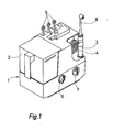
- the device comprises (fig.l) a base 1 in which is mounted a liquid pump, not shown, intended to send a liquid, for example water, contained in a removable tank 2, 'to a handpiece 3 connected to the pump by a conduit 4 and on which can be mounted interchangeable spray nozzles 5.
- the pump is actuated by a motor giving pulses at a frequency between 1000 to 4000 pulses per minute.
- the pump being driven by an asynchronous electric motor supplied by a 50 or 60 Hz network, its theoretical maximum frequency will be 3000 or 3600 pulses per minute, respectively. It is therefore reasonable in this case to locate the maximum frequency under load at 3000 pulses per minute.
- the operation of such an apparatus is described in particular in Swiss patent No 509 078.
- the device is provided with three spray nozzles 5 intended to project jets of pulsed liquid for oral hygiene, that is to say the washing of teeth and the massage of the gums.
- the head of these nozzles is designed so that the liquid flows in a heterogeneous jet so as to ensure an effective massage. Of the gums.
- Switching on of the device is controlled by a button 7 and a second button 6 adjusts the pressure.
- the apparatus further comprises another nozzle 8 called a nebulizing nozzle, the head of which differs from that of the nozzles 5 and is specially designed to spray the liquid in the form of a mist.
- a nebulizing nozzle the head of which differs from that of the nozzles 5 and is specially designed to spray the liquid in the form of a mist.
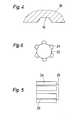
- This head is constituted, according to FIGS. 2 to 6, by an external envelope 9 delimiting an internal chamber 10 approximately cylindrical and which opens to the outside by a circular opening 11.
- a part 12 of this chamber 10 has a slightly larger diameter and delimits an internal shoulder 13 while the circular opening 11 is surrounded by a flange 14 directed inwards.
- the chamber 10 communicates with the supply conduit 4 coming from the pump via an internal conduit 15 which passes through the rod of the nozzle 8; an internal core 16, integral with the casing 9 protrudes inside this chamber and its function will be explained later.
- a cylindrical sleeve 17 which bears against the shoulder 13 and which is provided at its end directed towards the outside with a wall 18.
- the internal face of this wall 18 is provided with three grooves 19 arranged tangentially to the flared part of a conical central orifice 20 formed in the wall 18 and which opens on the external face of said wall, by a small cylindrical orifice 21
- the profile of the grooves is trapezoidal, as illustrated in FIG. 4.
- a cylindrical central axis 22 (fig. 5 and 6) which is blocked between the face d end 23 of the core 16 and the side wall 18 of the sleeve 17.
- This axis 22 is provided on its periphery with axial ribs 24, of approximately section semi-cylindrical, and which extend over most of its length leaving only a free space 25 on the side which is applied against the side wall 18 of the socket 17.
- the liquid coming from the reservoir 2 is sent by the pump into the conduit 15, it enters the liquid chamber 10, separates into several paths between the ribs 24 of the axis 22, then it reaches the wall 18 of the socket 17 and fills the small annular chamber 26 delimited by the end 25 of the axis and the wall 18, finally it flows with force in the three tangential grooves 19 formed in the wall 18, which cause it to take a vortex movement in the conical orifice 20 from which it exits in the form of mist through the small cylindrical orifice 21.
- the pressure of the liquid must be between 2.5 and 10 kg / cm 2 (peak value) or an average value between 1.5 and 3 kg / cm 2 .
- the three tangential grooves 19, the conical orifice 20 as well as the cylindrical outlet orifice 20 are dimensioned and arranged so as to obtain an optimum mist by the Vortrex effect.
- the water flow of the mist should be between 10 and 100 ml / minute because only a small amount of water gets inside the skin.
- This invention advantageously makes it possible to use this nozzle 8 for spraying different kinds of liquid on the face or if necessary another part of the body, for example solutions containing refreshing, toning, cleansing, flavoring moisturizing substances, etc.
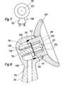
- FIGS. 7 and 8 is illustrated a second embodiment of a nebulizing nozzle 108 comprising, like the nozzle of FIG. 2, an envelope 109 inside which is formed a chamber 110 into which the supply conduit 115 opens.
- the circular opening of the envelope 109 is closed by a sleeve 117 pressing against an internal shoulder 113 delimited by a part 112 of the chamber 110 having a diameter greater than that of the interior part of the chamber.
- One end of the socket 117 is closed by a wall 118 which has the same structure as the wall 18 of the socket 17 in FIG. 2.
- a cylindrical axis 122 of the same structure as the axis 22 is supported on one side against the internal face of the wall 118 and the other against a core 116 of the chamber 110.
- the sleeve 117 is welded near the shoulder 113 to the envelope 109 by ultrasound.
- a tube 128 made of elastic material surrounding the core 116 and pressing on one side against the bottom of the chamber 110 and on the other against the cylindrical axis 122 ensures the axial positioning of this the latter in particular so that the external face of said axis 122 is in contact with the internal face of wall 118 and to prevent axis 122 moves under the effect of vibrations.
- a spring in place of the tube 128.
- the pressure to be exerted is relatively low and a tube of rubber or any other elastic material is sufficient and allows to have a symmetrical distribution of the pressure on the axis 122.
- a filter 129 is interposed between the axis 122 and the core 116 and it rests near its periphery on an internal shoulder 130 of the sleeve 117.
- the purpose of this filter is to prevent impurities block the orifice 121 of the nozzle or the grooves located inside the socket 117.
- a deflector 127 having the shape of a cup is rigidly fixed on the front part of the socket and is supported against the periphery of the opening of the envelope 109 of the nozzle 108.
- the shape of the deflector 127 makes it possible to avoid a great dispersion of the mist perpendicular to the axis of the orifice 121 which is thus directed towards the face under the shape of a cone whose axis is the axis of the orifice 121.
- the axis of the rod 131 and the head axis of the nozzle 108 are not perpendicular as is usually the case for the spray nozzles 5 and the nebulizing nozzle 8.
- the angular position of the rod 131 relative to the head of the nozzle facilitates this operation because thus the user can hold the handpiece in a more natural position ensuring that the mist is directed perpendicular to the skin.
- nebulizing nozzles could also be mounted on a tankless device, which would connect directly to a water source, for example a tap.
- a combined device the handpiece of which is designed to receive, as desired, a spray nozzle for the massage of the gums or a toothbrush, such as the device illustrated in FIG. 9.
- This device comprises a base 101 in which is mounted the pump for the liquid contained in the reservoir 102 supplying a handpiece 103 connected to the pump by a flexible hose 104.
- the device as illustrated comprises two toothbrushes 105a, a oral irrigation nozzle 105 and a nebulizing nozzle 108 mounted on the handpiece.
- the pump motor is controlled by the button 107 and the pump pressure is adjusted by the button 106.
- the handpiece 103 is provided with a hydraulic motor whose piston is mechanically connected with a carrying shaft -instruments to which can be attached by its rod, a toothbrush 105a or a spray nozzle 5 or a nebulizing nozzle 108.
- the brush 105a When the brush 105a is used the hydraulic motor is driven and oscillates the shaft with the brush tooth, if a nozzle is used the hydraulic motor does not work and it is the nozzle only which is supplied by the pump.
- Hydraulic motors for driving toothbrushes are known, a preferred type of these motors is described in French patent No 2,357,752 and US patent No 4,146,020.
- the piston of such an engine drives the shaft of the handpiece carrying the toothbrush in oscillating motion, itself being driven in oscillating motion under the action of a pulsed liquid. by the device pump and a return spring.
- the cylinder of the hydraulic motor is permanently connected to the outlet of the pump and in the case considered (above-mentioned patents) is a section of the water supply duct for the spray nozzle.
- a system made up of two distributors makes it possible to regulate the circulation of the liquid in three ways, 1 ° circulation in closed circuit that is to say to return to the upstream of the pump or in the container containing the liquid while the pump works and the handpiece is out of service, 2 0 to go out by the jet of nozzle for the massage of the gums, and 3 0 to actuate the piston without there being a flow of liquid only by the oscillating movement of a column of liquid, under the action of the pump.
- the piston of the hydraulic motor remains in principle stationary due to the low pressure pulses and the action of the return spring.
- Handpiece 103 is provided with such a hydraulic motor.
- the flexible hose 104 contains two conduits, one for the supply and the other for the return of the liquid.
- the distributor controlling the circulation in a closed circuit is controlled by a lever arranged outside the handpiece, the second is controlled directly by the shape of the foot for fixing the various accessories to the handpiece as will be described later. using Figures 10 to 12a.
- the piston of the hydraulic motor should not be driven.
- a spray nozzle 5 is mounted on the handpiece 103, efforts have so far been made to size the pump, the motor and the conduits so that the the spray nozzle remains stationary, the pressure pulses in the engine cylinder not being sufficient to overcome the force of the return spring.
- an angular oscillation of the nebulizing nozzle 108 with an amplitude between 10 o and 20, preferably 15 ° is beneficial because it ensures better distribution of the mist on the skin and increases the effect. massage.
- the oscillation frequency is preferably between 30 and 60 Hz.
- FIG 10 is shown the head of the handpiece 103 without cap.
- the lever controlling the distributor for circulating in a closed circuit of the liquid is illustrated in 133.
- the second distributor is controlled by a rod 134 secured to a sliding part 135 guided by a pin 136 and surrounding the hollow shaft 137 receiving the various accessories.
- the sliding part 135 illustrated in solid lines corresponds to the position of the dispenser allowing the liquid to pass through the hollow shaft for the supply of a nebulizing nozzle or a spray nozzle.
- the position indicated in dashed lines corresponds to the position where there is no liquid flow and the hydraulic motor drives the toothbrush.
- the sliding part 135 is brought back to the position indicated by dashed lines under the action of a spring not shown.
- a ring 138 integral with the shaft 137 allows the accessories to be fixed in the axial direction by snap-fastening, corresponding profiles being provided on the ring and the base of the rods of the instruments.
- the angular positioning of the accessories relative to the shaft is ensured by a shaft 137a rib in collaboration with a notch 139 and 140 (fig.11a, 12a) of the foot of the rods of the accessories.
- a notch 139 and 140 fig.11a, 12a
- the length of the two projections 108a is such that during the fixing of the rod 108 the sliding part 135 is pushed downwards thus actuating by the rod 134 the distributor opening to the liquid the circuit allowing it to arrive by the hollow shaft 137 to the nozzle 108.
- the stem base of a toothbrush 105a has the same configuration with the difference that the axial projections are shorter so that the sliding piece 135 is not pushed down and it remains at the position illustrated in dashed lines.
- the different characteristics of the motor and of the pump are adjusted so that the nebulizing nozzle is driven in angular oscillation of amplitude between 10 ° and 20 °, preferably 15 °, the amplitude for the toothbrush being greater than this value.
- the stem foot of this spray nozzle 5 has the same configuration as that of the nozzle 108, two axial projections 5a and one latching profile 142, but in addition the two projections 5a are extended by two tabs 5b to cooperate with a female profile 143 of the sliding part 135 and thus block the shaft 137 which would tend to oscillate.
- the invention is also applicable to known combined devices provided with an electric motor for driving an oscillating toothbrush movement; this engine can be according to the invention easily used for driving a nebulizing nozzle. In this case it is enough to adjust the characteristics of the motor to obtain the amplitude of the oscillation desired for the nebulizing nozzle, which is less than that of the brush, the frequency of oscillation can remain the same as for the brush.
Landscapes
- Health & Medical Sciences (AREA)
- Epidemiology (AREA)
- Pain & Pain Management (AREA)
- Physical Education & Sports Medicine (AREA)
- Rehabilitation Therapy (AREA)
- Life Sciences & Earth Sciences (AREA)
- Animal Behavior & Ethology (AREA)
- General Health & Medical Sciences (AREA)
- Public Health (AREA)
- Veterinary Medicine (AREA)
- Massaging Devices (AREA)
- Brushes (AREA)
Applications Claiming Priority (2)
| Application Number | Priority Date | Filing Date | Title |
|---|---|---|---|
| US26948881A | 1981-06-02 | 1981-06-02 | |
| US269488 | 1981-06-02 |
Publications (3)
| Publication Number | Publication Date |
|---|---|
| EP0066930A2 true EP0066930A2 (de) | 1982-12-15 |
| EP0066930A3 EP0066930A3 (en) | 1983-07-20 |
| EP0066930B1 EP0066930B1 (de) | 1986-03-12 |
Family
ID=23027466
Family Applications (1)
| Application Number | Title | Priority Date | Filing Date |
|---|---|---|---|
| EP82200674A Expired EP0066930B1 (de) | 1981-06-02 | 1982-06-02 | Gerät zur Körperpflege |
Country Status (2)
| Country | Link |
|---|---|
| EP (1) | EP0066930B1 (de) |
| DE (1) | DE3269793D1 (de) |
Cited By (4)
| Publication number | Priority date | Publication date | Assignee | Title |
|---|---|---|---|---|
| EP0298910A1 (de) * | 1987-06-22 | 1989-01-11 | Les Produits Associes L.P.A. Broxo S.A. | Gerät und Verfahren zur Pflege von Mund und Rachen |
| EP0550943A1 (de) * | 1990-04-05 | 1993-07-14 | Samuel Jackson Martz | Behandlungsgerät für Patienten mit papulosquamösen Leiden |
| WO2004034923A1 (de) * | 2002-10-17 | 2004-04-29 | Braun Gmbh | Munddusche und sprühdüse zur erzeugung eines flüssigkeitsstrahls sowie zahnreinigungssystem |
| CN113274158A (zh) * | 2021-05-11 | 2021-08-20 | 王丹 | 一种新型口腔护理器械及其护理方法 |
Family Cites Families (6)
| Publication number | Priority date | Publication date | Assignee | Title |
|---|---|---|---|---|
| CH468806A (fr) * | 1968-01-12 | 1969-02-28 | Sophindar Ets | Appareillage pour soins corporels |
| US3739983A (en) * | 1970-01-22 | 1973-06-19 | Woog Inst Rech | Multi-jet spray nozzle with a movable shutter member |
| CH518130A (de) * | 1971-01-19 | 1972-01-31 | Woog Inst Rech | Spritzdüse zum Ausstoss eines Flüssigkeitsstrahls, insbesondere zur Flüssigkeitsmassage und Zahnreinigung |
| US3871560A (en) * | 1973-08-01 | 1975-03-18 | Prod Associes Sa | Reservoir for a liquid pump including means for initially forcing liquid into the pump |
| JPS5047743A (de) * | 1973-08-15 | 1975-04-28 | ||
| US3861383A (en) * | 1973-09-24 | 1975-01-21 | Leslie J Kovach | Skin massaging instrument |
-
1982
- 1982-06-02 EP EP82200674A patent/EP0066930B1/de not_active Expired
- 1982-06-02 DE DE8282200674T patent/DE3269793D1/de not_active Expired
Cited By (5)
| Publication number | Priority date | Publication date | Assignee | Title |
|---|---|---|---|---|
| EP0298910A1 (de) * | 1987-06-22 | 1989-01-11 | Les Produits Associes L.P.A. Broxo S.A. | Gerät und Verfahren zur Pflege von Mund und Rachen |
| EP0550943A1 (de) * | 1990-04-05 | 1993-07-14 | Samuel Jackson Martz | Behandlungsgerät für Patienten mit papulosquamösen Leiden |
| WO2004034923A1 (de) * | 2002-10-17 | 2004-04-29 | Braun Gmbh | Munddusche und sprühdüse zur erzeugung eines flüssigkeitsstrahls sowie zahnreinigungssystem |
| US8052627B2 (en) | 2002-10-17 | 2011-11-08 | The Procter & Gamble Company | Spray nozzle and dental cleaning system |
| CN113274158A (zh) * | 2021-05-11 | 2021-08-20 | 王丹 | 一种新型口腔护理器械及其护理方法 |
Also Published As
| Publication number | Publication date |
|---|---|
| EP0066930A3 (en) | 1983-07-20 |
| DE3269793D1 (en) | 1986-04-17 |
| EP0066930B1 (de) | 1986-03-12 |
Similar Documents
| Publication | Publication Date | Title |
|---|---|---|
| EP2090187B1 (de) | Sprühkopf, der eine Sonotrode umfasst, die einen Kanal für die Produktzufuhr enthält | |
| JP3686409B2 (ja) | 口腔クリーニング装置 | |
| US5309590A (en) | Dentifrice/medication dispensing toothbrush | |
| FR2459052A1 (fr) | Inhalateur avec logement muni d'un moyen de fixation pour recevoir alternativement au choix deux reservoirs a liquide servant a des fins differentes | |
| FR2927237A1 (fr) | Dispositif de pulverisation d'un produit cosmetique avec soufflage d'air chaud ou froid | |
| EP2090378B1 (de) | Versprühvorrichtung, die eine Sonotrode umfasst | |
| EP2496363A1 (de) | Nebelerzeugungsvorrichtung | |
| EP1553883A1 (de) | Mikroabrasionvorrichtung | |
| EP0235487B1 (de) | Mit Wasser arbeitende Hygienevorrichtung zur Körperpflege | |
| EP0066930B1 (de) | Gerät zur Körperpflege | |
| WO2006048523A1 (fr) | Nebulisateur comprenant des moyens pour mettre en surpression un liquide a nebuliser | |
| EP0726743B1 (de) | SPRüHVORRICHTUNG FüR DIE ZAHNREINIGUNG | |
| FR2846639A1 (fr) | Dispositif de conditionnement et de distribution pour un produit liquide ou semi-liquide | |
| WO1999023975A1 (fr) | Brosse de nettoyage de dents amovible pour dispositif de pulverisation | |
| BE1004791A4 (fr) | Appareil distributeur de liquide. | |
| FR2787732A1 (fr) | Diffuseur mobile d'eau sous pression permettant d'ajouter des additifs en cours d'utilisation | |
| FR2515012A1 (fr) | Brosse a dents a dentifrice liquide injectable | |
| FR3118880A1 (fr) | Systeme d’atomisation et d’ejection de liquide pour une administration transdermique | |
| FR2781678A1 (fr) | Appareil de diffusion d'un produit liquide tel qu'un desinfectant pour le traitement de locaux ou de surfaces par voie aerienne | |
| EP0034119A1 (de) | Mechanisch angetriebene Zahnbürste | |
| WO2005051117A1 (fr) | Appareil de pulverisation d'un produit sur le corps humain | |
| EP0518723B1 (de) | Verfahren und Vorrichtung zur Ausgabe eines viskösen Gels | |
| WO1999044463A1 (fr) | Dispositif de stimulation vibratoire transcutanee et utilisation de ce dispositif | |
| FR3142329A1 (fr) | Dispositif d’atomisation d’un produit cosmétique liquide, notamment in produit de maquillage | |
| CH508396A (fr) | Appareil pour soins dentaires |
Legal Events
| Date | Code | Title | Description |
|---|---|---|---|
| PUAI | Public reference made under article 153(3) epc to a published international application that has entered the european phase |
Free format text: ORIGINAL CODE: 0009012 |
|
| AK | Designated contracting states |
Designated state(s): CH DE FR GB IT LI |
|
| PUAL | Search report despatched |
Free format text: ORIGINAL CODE: 0009013 |
|
| RHK1 | Main classification (correction) |
Ipc: A61C 17/02 |
|
| AK | Designated contracting states |
Designated state(s): CH DE FR GB IT LI |
|
| 17P | Request for examination filed |
Effective date: 19831223 |
|
| GRAA | (expected) grant |
Free format text: ORIGINAL CODE: 0009210 |
|
| AK | Designated contracting states |
Kind code of ref document: B1 Designated state(s): CH DE FR GB IT LI |
|
| PG25 | Lapsed in a contracting state [announced via postgrant information from national office to epo] |
Ref country code: IT Free format text: LAPSE BECAUSE OF FAILURE TO SUBMIT A TRANSLATION OF THE DESCRIPTION OR TO PAY THE FEE WITHIN THE PRESCRIBED TIME-LIMIT;WARNING: LAPSES OF ITALIAN PATENTS WITH EFFECTIVE DATE BEFORE 2007 MAY HAVE OCCURRED AT ANY TIME BEFORE 2007. THE CORRECT EFFECTIVE DATE MAY BE DIFFERENT FROM THE ONE RECORDED. Effective date: 19860312 |
|
| REF | Corresponds to: |
Ref document number: 3269793 Country of ref document: DE Date of ref document: 19860417 |
|
| PLBE | No opposition filed within time limit |
Free format text: ORIGINAL CODE: 0009261 |
|
| STAA | Information on the status of an ep patent application or granted ep patent |
Free format text: STATUS: NO OPPOSITION FILED WITHIN TIME LIMIT |
|
| 26N | No opposition filed | ||
| PGFP | Annual fee paid to national office [announced via postgrant information from national office to epo] |
Ref country code: CH Payment date: 19890420 Year of fee payment: 8 |
|
| PGFP | Annual fee paid to national office [announced via postgrant information from national office to epo] |
Ref country code: DE Payment date: 19890424 Year of fee payment: 8 |
|
| PGFP | Annual fee paid to national office [announced via postgrant information from national office to epo] |
Ref country code: GB Payment date: 19890531 Year of fee payment: 8 |
|
| PGFP | Annual fee paid to national office [announced via postgrant information from national office to epo] |
Ref country code: FR Payment date: 19890619 Year of fee payment: 8 |
|
| PG25 | Lapsed in a contracting state [announced via postgrant information from national office to epo] |
Ref country code: GB Effective date: 19900602 |
|
| PG25 | Lapsed in a contracting state [announced via postgrant information from national office to epo] |
Ref country code: LI Effective date: 19900630 Ref country code: CH Effective date: 19900630 |
|
| GBPC | Gb: european patent ceased through non-payment of renewal fee | ||
| PG25 | Lapsed in a contracting state [announced via postgrant information from national office to epo] |
Ref country code: FR Effective date: 19910228 |
|
| REG | Reference to a national code |
Ref country code: CH Ref legal event code: PL |
|
| PG25 | Lapsed in a contracting state [announced via postgrant information from national office to epo] |
Ref country code: DE Effective date: 19910301 |
|
| REG | Reference to a national code |
Ref country code: FR Ref legal event code: ST |