EP0066984B1 - System zur Verteilung von pulverförmigem Material - Google Patents
System zur Verteilung von pulverförmigem Material Download PDFInfo
- Publication number
- EP0066984B1 EP0066984B1 EP82302551A EP82302551A EP0066984B1 EP 0066984 B1 EP0066984 B1 EP 0066984B1 EP 82302551 A EP82302551 A EP 82302551A EP 82302551 A EP82302551 A EP 82302551A EP 0066984 B1 EP0066984 B1 EP 0066984B1
- Authority
- EP
- European Patent Office
- Prior art keywords
- inlet
- vessel
- tubes
- gas
- outlet
- Prior art date
- Legal status (The legal status is an assumption and is not a legal conclusion. Google has not performed a legal analysis and makes no representation as to the accuracy of the status listed.)
- Expired
Links
- 239000011236 particulate material Substances 0.000 title claims description 20
- 239000000463 material Substances 0.000 claims description 13
- 238000000034 method Methods 0.000 claims description 7
- 238000010304 firing Methods 0.000 claims description 6
- 239000000203 mixture Substances 0.000 claims description 2
- 239000007787 solid Substances 0.000 description 8
- 239000000446 fuel Substances 0.000 description 7
- 238000002485 combustion reaction Methods 0.000 description 6
- 239000003245 coal Substances 0.000 description 5
- 230000007246 mechanism Effects 0.000 description 3
- 238000002347 injection Methods 0.000 description 2
- 239000007924 injection Substances 0.000 description 2
- 241000238413 Octopus Species 0.000 description 1
- 239000000428 dust Substances 0.000 description 1
- 230000000694 effects Effects 0.000 description 1
- 238000012423 maintenance Methods 0.000 description 1
- 238000012544 monitoring process Methods 0.000 description 1
- 239000002245 particle Substances 0.000 description 1
- 238000007789 sealing Methods 0.000 description 1
- 239000000725 suspension Substances 0.000 description 1
Images


Classifications
-
- F—MECHANICAL ENGINEERING; LIGHTING; HEATING; WEAPONS; BLASTING
- F23—COMBUSTION APPARATUS; COMBUSTION PROCESSES
- F23K—FEEDING FUEL TO COMBUSTION APPARATUS
- F23K3/00—Feeding or distributing of lump or pulverulent fuel to combustion apparatus
- F23K3/02—Pneumatic feeding arrangements, i.e. by air blast
Definitions
- This invention concerns a system for distributing particulate material.
- the present invention has particular, although not exclusive, reference to such systems employed for distributing fuel to burners or outlets in a kiln or other equipment in which the fuel is to be burnt, for example a furnace or boiler, and in these applications can be regarded as a "firing system".
- the fuel is often conveyed pneumatically, by entrainment, from a main input point to a distribution device and thence to the burners.
- this distribution device per se usually involves some kind of mechanism having moving parts which are prone to malfunctioning thus resulting in unsatisfactory operation of the plant concerned and high maintenance costs.
- the mechanism concerned can, as a rule, only serve a limited number of delivery points and the maximum is of the order of twenty, but in some systems can be less, for example the 'Octopus' system (Registered Trade Mark) serves eight. A number of mechanisms would, therefore, be required should the number of delivery points exceed the designed capacity, thus adding appreciably to the capital cost of the plant.
- An object of the present invention is to provide an improved system for distributing particulate material substantially obviating the disadvantages of conventional systems.
- a further object of the invention is to provide a method of operating such an improved system.
- a system for distributing particulate material including a vessel having an inlet for particulate material, a gas manifold, a plurality of inlet tubes connected to the gas manifold and adapted to extend into the vessel, a gas inlet to the manifold, and a plurality of outlet tubes extending through the inlet tubes to define passages therebetween and having outlet connections exteriorly of the vessel, the outlet tubes defining in use, paths for entrained particulate material.
- the vessel is conveniently a pressure vessel and the top thereof may incorporate the inlet for particulate material.
- the gas manifold may be located externally or internally of the vessel and may be in the form of a ring main for a gas, conveniently air.
- the inlet tubes are connected to the gas manifold and the outlet tubes may extend co-axially therethrough to define an annular passage for the gas which, in use, would flow downwardly into the vessel.
- a cylinder advantageously of shorter length than the inlet or outlet tubes may be provided within each annular passage and is preferably adapted for sliding movement relative to the inlet and outlet tubes, the cylinder being disposed near to the free ends of the inlet and outlet tubes within the vessel.
- a means for adjusting the position of the cylinder is conveniently provided and may comprise a threaded rod which is secured at one end to the cylinder and protrudes outside the vessel where a simple nut adjustment assembly is provided.
- the purpose of the sliding cylinder is in effect to extend or shorten the length of the outlet tube thereby controlling, in use, the solids/air mass ratio and adjustment can take place during operation of the system.
- each outlet tube may be positionally adjustable relative to the inlet tube.
- a method of operating a system for distributing particulate material including the steps of passing particulate material into the vessel through the inlet thereof, feeding a positive pressure gas flow to the gas inlet of the manifold, and passing the gas through the passages defined between the inlet tubes and the outlet tubes to issue into the material in the vessel to entrain some of the material in the vicinity of the free ends of the tubes, the mixture of gas and material entrained flowing through the outlet tubes for discharge through the outlet connections.
- the method may also include the step of varying the position of the cylinder to control the material to air mass ratio, each cylinder being actuable independently and during operation of the system.
- the present invention thus differs from the prior art disclosed in EP-A-63629 and AT-B-92107 in that the outlet tubes pass through the inlet tubes and only one source of conveying gas is required for distributing the particulate material.
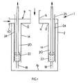
- a system for distributing particulate material is depicted at 1 and comprises a pressure vessel 2 having in the top 4 thereof an inlet 6 for particulate material; the inlet 6 may incorporate a rotary valve (not shown) for sealing the vessel 2 and monitoring the amount of material passing therethrough into vessel 2.
- a gas manifold 8 is located at the top of the vessel 2 and has an inlet 10 and a plurality of outlets 12 to each of which is connected an inlet tube 14 depending therefrom into the vessel 2 and terminating at a distance from the base 16 thereof. Extending co-axially through the inlet tubes 14 are outlet tubes 18 between each pair of which is defined an annular passage 20.
- the outlet tubes 18 terminate in the vicinity of the free ends of the inlet tubes 14 and extend through the gas manifold 8 to the exterior of the vessel 2 and are suitably adapted for connection to pipes (not shown) for remote connection to points of use (not shown).
- a cylinder 22 is disposed within each annular passage 20 towards the lower end thereof, as viewed in Figures 1 and 3 and has attached thereto a rod 24 having a threaded portion at least at its relatively outer end 25 for engagement with a lock nut arrangement 26, the outer end 25 having a knurled nut 27.
- the system as described may be employed as a firing system for a kiln, the particulate material conveyed being crushed or pulverised coal, and the outlet tubes 18 being connected to the combustion zones of the kiln.
- the coal is admitted to the vessel 2 through the inlet 6 and air is passed into the manifold 8 through the inlet 10.
- the air then travels down through each annular passage 20 and entrains the coal in the vicinity of the free ends of the inlet tubes 14.
- the entrained coal is conveyed up through each outlet tube 18 for transport to an injection point in the kiln.
- the solids/air mass ratio may be varied by raising or lowering the cylinder 22 in each annular passage 20 thereby affording individual control on the amount of fuel passed the relevant injection point in the kiln.
- hot particulate material from a fluidised combustion bed is admitted through the inlet 6 and air is passed into the manifold 8 through the inlet 10.
- the air then travels down through each annular passage 20 and entrains the particulate material in the vicinity of the free ends of the inlet tubes 14.
- the entrained material is conveyed up through each outlet tube 18 for transport either directly back to the fluidised combustion bed or indirectly through a size classification system.
- the solids/air mass ratio may be varied by raising or lowering the cylinder 22 in each annular passage 20. In this application of the system fewer outlet connections may be employed than for the kiln firing system.
- the system of the present invention has no moving parts save for the adjustment of the cylinder 22 and has the capacity of achieving a high solids/air mass ratio thus avoiding the disadvantage of high excess air levels associated with conventional systems.
Landscapes
- Engineering & Computer Science (AREA)
- Chemical & Material Sciences (AREA)
- Combustion & Propulsion (AREA)
- Mechanical Engineering (AREA)
- General Engineering & Computer Science (AREA)
- Feeding, Discharge, Calcimining, Fusing, And Gas-Generation Devices (AREA)
- Devices And Processes Conducted In The Presence Of Fluids And Solid Particles (AREA)
- Air Transport Of Granular Materials (AREA)
Claims (11)
Applications Claiming Priority (4)
| Application Number | Priority Date | Filing Date | Title |
|---|---|---|---|
| GB8117663 | 1981-06-09 | ||
| GB8117663 | 1981-06-09 | ||
| GB8134594 | 1981-11-17 | ||
| GB8134594 | 1981-11-17 |
Publications (2)
| Publication Number | Publication Date |
|---|---|
| EP0066984A1 EP0066984A1 (de) | 1982-12-15 |
| EP0066984B1 true EP0066984B1 (de) | 1984-07-25 |
Family
ID=26279739
Family Applications (1)
| Application Number | Title | Priority Date | Filing Date |
|---|---|---|---|
| EP82302551A Expired EP0066984B1 (de) | 1981-06-09 | 1982-05-19 | System zur Verteilung von pulverförmigem Material |
Country Status (3)
| Country | Link |
|---|---|
| EP (1) | EP0066984B1 (de) |
| DE (1) | DE3260457D1 (de) |
| GB (1) | GB2101064B (de) |
Families Citing this family (1)
| Publication number | Priority date | Publication date | Assignee | Title |
|---|---|---|---|---|
| US8951315B2 (en) | 2008-11-12 | 2015-02-10 | Exxonmobil Research And Engineering Company | Method of injecting fuel into a gasifier via pressurization |
Citations (2)
| Publication number | Priority date | Publication date | Assignee | Title |
|---|---|---|---|---|
| AT92107B (de) * | 1918-11-26 | 1923-04-10 | Comb E Economica Societa Anoni | Brennstaubfeuerung. |
| EP0063629A1 (de) * | 1981-04-29 | 1982-11-03 | Ruhrkohle-Carborat GmbH | Kohlenstaubeintrag |
Family Cites Families (3)
| Publication number | Priority date | Publication date | Assignee | Title |
|---|---|---|---|---|
| DE93436C (de) * | ||||
| US1838521A (en) * | 1928-03-17 | 1931-12-29 | Milton W Arrowood | Apparatus for and method of feeding powdered fuel |
| FR1562781A (de) * | 1967-05-12 | 1969-04-11 |
-
1982
- 1982-05-19 DE DE8282302551T patent/DE3260457D1/de not_active Expired
- 1982-05-19 EP EP82302551A patent/EP0066984B1/de not_active Expired
- 1982-05-21 GB GB08214887A patent/GB2101064B/en not_active Expired
Patent Citations (2)
| Publication number | Priority date | Publication date | Assignee | Title |
|---|---|---|---|---|
| AT92107B (de) * | 1918-11-26 | 1923-04-10 | Comb E Economica Societa Anoni | Brennstaubfeuerung. |
| EP0063629A1 (de) * | 1981-04-29 | 1982-11-03 | Ruhrkohle-Carborat GmbH | Kohlenstaubeintrag |
Also Published As
| Publication number | Publication date |
|---|---|
| GB2101064B (en) | 1985-01-16 |
| DE3260457D1 (en) | 1984-08-30 |
| EP0066984A1 (de) | 1982-12-15 |
| GB2101064A (en) | 1983-01-12 |
Similar Documents
| Publication | Publication Date | Title |
|---|---|---|
| DE3529144C2 (de) | ||
| CA1047074A (en) | Disperser | |
| US4131072A (en) | Apparatus for individual controlled distribution of powdered solid fuel to plural burning units | |
| US4250816A (en) | Particulate solid fuel combustion system | |
| CA1037521A (en) | Distributor | |
| CN1232538A (zh) | 用于输送并引导反应气体及固体进入熔炼炉的方法及一种为实现该目的而设计的可多级调节的燃烧器 | |
| GB1566302A (en) | Method of and apparatus for providing a metered supply of particulate material | |
| SK49898A3 (en) | Process and device for conveying a finely divided solid | |
| CN1010054B (zh) | 煤粉燃烧装置 | |
| US4279549A (en) | Method and apparatus of self-regulation for a pneumatic conveyor | |
| GB2124781A (en) | Measurement of solid particle/gas suspension flow rates | |
| US4593630A (en) | Apparatus for fluidizing a particulate material in a conveying gas | |
| CA1285180C (en) | Pulverized coal flow control system | |
| US4728287A (en) | Apparatus for uniformly drawing and cooling pyroprocessed particulate material | |
| CA1048761A (en) | Conduit | |
| US4367685A (en) | Process and apparatus for precisely metering quantities of granular or pulverulent solids | |
| US3962128A (en) | Coal dust fuel distribution system and method of manufacturing activated carbon | |
| EP0066984A1 (de) | System zur Verteilung von pulverförmigem Material | |
| HU209806B (en) | Method and apparatus for introducing additives into cupola furnace | |
| US3301544A (en) | Blast furnace pulverized coal firing system | |
| US4413932A (en) | Pneumatic conveyors for flow of gas-borne particulate material | |
| US4530290A (en) | Apparatus for fluidizing a particulate material in a conveying gas | |
| US3033134A (en) | Method of and apparatus for regulating the air-borne material delivered through at least two branch conduits | |
| HU196150B (en) | Apparatus for feeding boilers of pulverized coal firing | |
| US4354439A (en) | Method of and a device for feeding solid fuel in a fluidized bed hearth |
Legal Events
| Date | Code | Title | Description |
|---|---|---|---|
| PUAI | Public reference made under article 153(3) epc to a published international application that has entered the european phase |
Free format text: ORIGINAL CODE: 0009012 |
|
| AK | Designated contracting states |
Designated state(s): DE FR IT SE |
|
| 17P | Request for examination filed |
Effective date: 19821115 |
|
| ITF | It: translation for a ep patent filed | ||
| GRAA | (expected) grant |
Free format text: ORIGINAL CODE: 0009210 |
|
| AK | Designated contracting states |
Designated state(s): DE FR IT SE |
|
| REF | Corresponds to: |
Ref document number: 3260457 Country of ref document: DE Date of ref document: 19840830 |
|
| ET | Fr: translation filed | ||
| PLBE | No opposition filed within time limit |
Free format text: ORIGINAL CODE: 0009261 |
|
| STAA | Information on the status of an ep patent application or granted ep patent |
Free format text: STATUS: NO OPPOSITION FILED WITHIN TIME LIMIT |
|
| 26N | No opposition filed | ||
| PGFP | Annual fee paid to national office [announced via postgrant information from national office to epo] |
Ref country code: SE Payment date: 19910327 Year of fee payment: 10 |
|
| PGFP | Annual fee paid to national office [announced via postgrant information from national office to epo] |
Ref country code: FR Payment date: 19910409 Year of fee payment: 10 |
|
| PGFP | Annual fee paid to national office [announced via postgrant information from national office to epo] |
Ref country code: DE Payment date: 19910515 Year of fee payment: 10 |
|
| ITTA | It: last paid annual fee | ||
| PG25 | Lapsed in a contracting state [announced via postgrant information from national office to epo] |
Ref country code: SE Effective date: 19920520 |
|
| PG25 | Lapsed in a contracting state [announced via postgrant information from national office to epo] |
Ref country code: FR Effective date: 19930129 |
|
| PG25 | Lapsed in a contracting state [announced via postgrant information from national office to epo] |
Ref country code: DE Effective date: 19930202 |
|
| REG | Reference to a national code |
Ref country code: FR Ref legal event code: ST |
|
| EUG | Se: european patent has lapsed |
Ref document number: 82302551.5 Effective date: 19921204 |