EP0067027A1 - Regenerator für digitale Signale - Google Patents
Regenerator für digitale Signale Download PDFInfo
- Publication number
- EP0067027A1 EP0067027A1 EP82302807A EP82302807A EP0067027A1 EP 0067027 A1 EP0067027 A1 EP 0067027A1 EP 82302807 A EP82302807 A EP 82302807A EP 82302807 A EP82302807 A EP 82302807A EP 0067027 A1 EP0067027 A1 EP 0067027A1
- Authority
- EP
- European Patent Office
- Prior art keywords
- network
- repeater
- control
- output
- compensation signal
- Prior art date
- Legal status (The legal status is an assumption and is not a legal conclusion. Google has not performed a legal analysis and makes no representation as to the accuracy of the status listed.)
- Granted
Links
- 230000005540 biological transmission Effects 0.000 claims abstract description 12
- 238000001914 filtration Methods 0.000 claims description 6
- 230000000694 effects Effects 0.000 claims description 4
- 230000003139 buffering effect Effects 0.000 claims description 3
- 230000001419 dependent effect Effects 0.000 claims description 3
- 230000001172 regenerating effect Effects 0.000 claims 7
- 238000003199 nucleic acid amplification method Methods 0.000 abstract description 6
- 230000003321 amplification Effects 0.000 abstract description 3
- 230000008929 regeneration Effects 0.000 description 6
- 238000011069 regeneration method Methods 0.000 description 6
- 230000008878 coupling Effects 0.000 description 4
- 238000010168 coupling process Methods 0.000 description 4
- 238000005859 coupling reaction Methods 0.000 description 4
- 238000001228 spectrum Methods 0.000 description 4
- 238000000034 method Methods 0.000 description 3
- 230000008901 benefit Effects 0.000 description 2
- 238000007796 conventional method Methods 0.000 description 2
- 230000007246 mechanism Effects 0.000 description 2
- 241000256683 Peregrinus Species 0.000 description 1
- 230000002238 attenuated effect Effects 0.000 description 1
- 238000010586 diagram Methods 0.000 description 1
- 230000009467 reduction Effects 0.000 description 1
- 238000007493 shaping process Methods 0.000 description 1
- 230000001052 transient effect Effects 0.000 description 1
Images

Classifications
-
- H—ELECTRICITY
- H04—ELECTRIC COMMUNICATION TECHNIQUE
- H04B—TRANSMISSION
- H04B1/00—Details of transmission systems, not covered by a single one of groups H04B3/00 - H04B13/00; Details of transmission systems not characterised by the medium used for transmission
- H04B1/62—Details of transmission systems, not covered by a single one of groups H04B3/00 - H04B13/00; Details of transmission systems not characterised by the medium used for transmission for providing a predistortion of the signal in the transmitter and corresponding correction in the receiver, e.g. for improving the signal/noise ratio
- H04B1/64—Volume compression or expansion arrangements
-
- H—ELECTRICITY
- H04—ELECTRIC COMMUNICATION TECHNIQUE
- H04L—TRANSMISSION OF DIGITAL INFORMATION, e.g. TELEGRAPHIC COMMUNICATION
- H04L25/00—Baseband systems
- H04L25/02—Details ; arrangements for supplying electrical power along data transmission lines
- H04L25/03—Shaping networks in transmitter or receiver, e.g. adaptive shaping networks
- H04L25/03006—Arrangements for removing intersymbol interference
- H04L25/03012—Arrangements for removing intersymbol interference operating in the time domain
- H04L25/03019—Arrangements for removing intersymbol interference operating in the time domain adaptive, i.e. capable of adjustment during data reception
Definitions
- This invention relates to digital information transmission systems including twisted wire pair transmission lines, and in particular to equalisation for digital repeaters in the presence of near-end crosstalk.
- a transmission system involving transmission over symmetric (balanced) wire pairs requires repeaters to be placed at intervals, typically less than 2 km apart. Such repeaters reduce signal distortion by equalisation, and by employing amplification restore the signal to a suitable level for retransmission and well above the level of the near-end crosstalk from other systems using the same route.
- Fig. 1 of the accompanying drawings shows a section of such a route in which a repeater 1 transmits high amplitude signals into a symmetric pair at point 2. These signals are attenuated whilst travelling down the pair 3 to point 4, where they are received by a subsequent repeater 5.
- This crosstalk is near-end crosstalk coupling due to imperfect balance of the cable pairs and is indicated in Fig. 1 by a curved arrow between points 7 and 4.
- a similar coupling occurs between points 2 and 9.
- Other crosstalk mechanisms may also exist. For example, near-end crosstalk can occur between systems transmitting in the same direction if transmitted and received signals come within close proximity to each other.
- each repeater For a digital system the functions of each repeater are usually to re-amplify, regenerate and retime the symbols being transmitted.
- the function of re-amplification involves equalisation (inversion) of the linear filtering effect of the cable pair such that thesubsequent pulse spectrum has a predetermined shape meeting Nyquist's criterion for no intersymbol interference.
- the intersymbol interference is negated by selectively amplifying the higher frequencies by the magnitude of attenuation suffered by them in transmission.
- the gain of the re-amplification function correspondingly increases with frequency, at least up to a frequency of approximately one half of the symbol rate. This increasing of gain with frequency is unfortunate, since it simultaneously amplifies crosstalk, whilst the coupling mechanism producing the crosstalk deteriorates with increasing frequency.
- the present invention is intended to overcome this problem and thus provides a digital repeater in or for a digital transmission system including a twisted-wire pair transmission line and at least one digital repeater, which repeater employs feedback equalisation for an incoming signal in such a manner as to reduce intersymbol interference thereon whilst minimising near-end crosstalk gain.
- the intersymbol interference is preferably cancelled by means of a compensation signal derived from the pulse regeneration and retiming functions of the repeater.
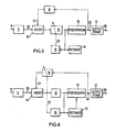
- Fig. 2 shows a basic repeater circuit arrangement consisting of a linear network 11 followed by an adder 12, a second linear network 13 whose output is connected to a retimer 14, regenerator 15, and a control network 18.
- Regenerator 15 has its output connected to a network 16 and an output driver (output stage) 17.
- an input signal with crosstalk 19 is filtered by network 11, and the filtered signal 20 is applied to adder 12 which sums it with an inverted replica of 21, which is the output signal (regenerated signal) 22 of regenerator 15 when filtered and scaled by network 16.
- the output signal of adder 12 is applied to network 13 which is such as to produce a signal 23 suitable to feed regenerator 15, and also feed retimer 14 comprising the usual arrangement of a linear network followed by a non-linear network, such as full-wave rectifier, and a further linear network of a resonant variety.
- the output signal 22 of regenerator 15 is amplified and shaped by output stage 17 to form a signal 24 suitable to be transmitted to line and to buffer the effects of different impedances of different pairs from the signal through network 16.
- network 16 can include its own buffering function
- the control network 18f typically consisting of a high impedance peak detector followed by a low pass network, to produce a direct current 25 that can affect the linear characteristics of network 11 prior to the point of entry of the signal 21.
- This has the advantage that all properties of most signals in the repeater, such as that of regenerator 15, remain constant. It has the disadvantage, however, that the crosstalk spectrum of signal 23 depends on the pair length and cannot be optimally chosen for more than one length, such as the maximum.
- Fig. 3 differs from Fig. 2 only in that the network under control is network 13, that is after the point of entry of the signal 21. This may be useful where the cancellation/ reduction techniques are required to be effective on the longest lines, but not where crosstalk amplification is to be reduced also on short lines.
- the network under control is network 16, that is affecting the signal itself. This results in the near-end crosstalk spectrum at entry to the regenerator 15 being independent of pair length, but with signal properties at this point that do vary with pair length.
- the network 16 should, preferably, be chosen in such a way that the signal passed to the non-linear circuit in the retimer 14 has the required properties to minimise pattern dependent jitter (e.g. a pulse shape that is symmetric in time or whose spectrum is symmetrically disposed about a frequency equal to half the symbol rate in the frequency domain).
- pattern dependent jitter e.g. a pulse shape that is symmetric in time or whose spectrum is symmetrically disposed about a frequency equal to half the symbol rate in the frequency domain.
- the signal 21 caused by a symbol must be small or nil until the corresponding signal 20 is considerable and regeneration is complete. Therefore, the properties for low jitter are achieved by ensuring that the signal 21 after bus time has then the shape that, when added to signal 20, produces the required symmetry.
- network 16 When regeneration occurs incorrectly, perhaps due to an exceptionally large crosstalk transient, an incorrect signal flows through network 16, causing distortion that will tend to encourage subsequent errors. This error multiplication effect is dependent on the choice of networks 11, 13 and 16.
- network 16 has a low-pass characteristic that can result in a situation where following an error, typically only one additional error occurs.
- a system carrying a 2048 Kbit/s multiplex of 30 telephony channels and employing AMI,. HDB3, 4B-3T or a similar line code can with the techniques described above achieve, on the same cable type, greater cable section length, a greater number of channels on each system, or a combination of these.
- the embodiments described above include automatic compensation for different lengths of the cable section, and involve automatic control of a network or networks such that the signal entering the regeneration function remains unchanged in its important properties, such as amplitude, and ensures freedom from intersymbol interference.
- the linear network 11 in Fig. 2 is formed by an equaliser, comprising one or more resonant bridged T sections, followed by an automatic line build out circuit.
- This last circuit can consist of filter sections in which each of several resistance elements is created by the slope resistance of a diode through which the control current 25 is passed. If the signals 20 and 21 can be from current sources the adder 12 can be simply a common impedence through which those currents are passed.
- the linear network 13 can be an amplifier, and its gain may be arranged to vary with frequency in order to fulfill part of the equalisation and pulse shaping functions.
- the retimer 14, regenerator 15 and output stage 17 can be as described in Chapter 14 and earlier chapters of "Digital Transmission Systems", Revised 2nd Edition by P. Bylanski and D.G.W.
- the filtering and scaling network 16 may be a simple low pass network comprising a series resistance followed by a shunt capacitance, together with any necessary a.c. coupling.
- the control network 18 may be a peak detector formed by a half wave rectifier followed by a large capacitance with large shunt resistance whose potential difference is used to drive a current source.
Landscapes
- Engineering & Computer Science (AREA)
- Computer Networks & Wireless Communication (AREA)
- Signal Processing (AREA)
- Power Engineering (AREA)
- Cable Transmission Systems, Equalization Of Radio And Reduction Of Echo (AREA)
- Reduction Or Emphasis Of Bandwidth Of Signals (AREA)
- Dc Digital Transmission (AREA)
- Communication Control (AREA)
- Oscillators With Electromechanical Resonators (AREA)
- Amplifiers (AREA)
- Optical Communication System (AREA)
- Interface Circuits In Exchanges (AREA)
- Time-Division Multiplex Systems (AREA)
Priority Applications (1)
| Application Number | Priority Date | Filing Date | Title |
|---|---|---|---|
| AT82302807T ATE19448T1 (de) | 1981-06-04 | 1982-06-01 | Regenerator fuer digitale signale. |
Applications Claiming Priority (2)
| Application Number | Priority Date | Filing Date | Title |
|---|---|---|---|
| GB08117139A GB2101850B (en) | 1981-06-04 | 1981-06-04 | Digital transmission systems |
| GB8117139 | 1981-06-04 |
Publications (2)
| Publication Number | Publication Date |
|---|---|
| EP0067027A1 true EP0067027A1 (de) | 1982-12-15 |
| EP0067027B1 EP0067027B1 (de) | 1986-04-23 |
Family
ID=10522275
Family Applications (1)
| Application Number | Title | Priority Date | Filing Date |
|---|---|---|---|
| EP82302807A Expired EP0067027B1 (de) | 1981-06-04 | 1982-06-01 | Regenerator für digitale Signale |
Country Status (13)
| Country | Link |
|---|---|
| US (1) | US4484336A (de) |
| EP (1) | EP0067027B1 (de) |
| JP (1) | JPS57211843A (de) |
| KR (1) | KR840001024A (de) |
| AT (1) | ATE19448T1 (de) |
| AU (1) | AU550099B2 (de) |
| BE (1) | BE893406A (de) |
| DE (1) | DE3270735D1 (de) |
| ES (1) | ES8308177A1 (de) |
| GB (1) | GB2101850B (de) |
| MX (1) | MX151293A (de) |
| NO (1) | NO154780C (de) |
| NZ (1) | NZ200824A (de) |
Families Citing this family (6)
| Publication number | Priority date | Publication date | Assignee | Title |
|---|---|---|---|---|
| US4679227A (en) * | 1985-05-20 | 1987-07-07 | Telebit Corporation | Ensemble modem structure for imperfect transmission media |
| US5157697A (en) * | 1991-03-21 | 1992-10-20 | Novatel Communications, Ltd. | Receiver employing correlation technique for canceling cross-talk between in-phase and quadrature channels prior to decoding |
| US5400360A (en) * | 1993-03-23 | 1995-03-21 | Limitorque Corporation | Repeater for a digital control system |
| US5608757A (en) * | 1994-06-03 | 1997-03-04 | Dsc Communications Corporation | High speed transport system |
| US7236550B1 (en) * | 2004-11-01 | 2007-06-26 | Synopsys, Inc. | Method and apparatus for tail cancellation equalization |
| KR100634263B1 (ko) | 2005-07-01 | 2006-10-13 | 서울통신기술 주식회사 | 디지털 통신 시스템의 신호 처리 방법 및 그 장치 |
Citations (3)
| Publication number | Priority date | Publication date | Assignee | Title |
|---|---|---|---|---|
| DE2257929A1 (de) * | 1971-12-27 | 1973-07-12 | Ibm | Empfangsanordnung und verfahren zur entzerrung uebertragungsgangbeeinflusster codierter daten |
| GB1429354A (en) * | 1972-06-01 | 1976-03-24 | Ibm | Automa5tic equalizer |
| US4078157A (en) * | 1976-10-18 | 1978-03-07 | Gte Automatic Electric Laboratories Incorporated | Method and apparatus for regenerating a modified duobinary signal |
Family Cites Families (3)
| Publication number | Priority date | Publication date | Assignee | Title |
|---|---|---|---|---|
| US3304508A (en) * | 1964-05-14 | 1967-02-14 | Ericsson Telefon Ab L M | Level regenerating arrangement for transmission of bipolar signals |
| NL139150B (nl) * | 1969-05-06 | 1973-06-15 | Nederlanden Staat | Bipolaire overdrager. |
| DE2421784C3 (de) * | 1974-05-06 | 1980-07-17 | Siemens Ag, 1000 Berlin Und 8000 Muenchen | Streckengerät für Übertragungsstrecken mit Koaxialkabeln zur Übertragung digitaler Signale |
-
1981
- 1981-06-04 GB GB08117139A patent/GB2101850B/en not_active Expired
-
1982
- 1982-05-21 US US06/380,789 patent/US4484336A/en not_active Expired - Fee Related
- 1982-05-28 NO NO821784A patent/NO154780C/no unknown
- 1982-05-29 ES ES512679A patent/ES8308177A1/es not_active Expired
- 1982-05-31 AU AU84318/82A patent/AU550099B2/en not_active Ceased
- 1982-06-01 AT AT82302807T patent/ATE19448T1/de not_active IP Right Cessation
- 1982-06-01 DE DE8282302807T patent/DE3270735D1/de not_active Expired
- 1982-06-01 EP EP82302807A patent/EP0067027B1/de not_active Expired
- 1982-06-02 JP JP57093259A patent/JPS57211843A/ja active Pending
- 1982-06-02 NZ NZ200824A patent/NZ200824A/en unknown
- 1982-06-02 MX MX192967A patent/MX151293A/es unknown
- 1982-06-04 BE BE2/59731A patent/BE893406A/fr not_active IP Right Cessation
- 1982-06-04 KR KR1019820002521A patent/KR840001024A/ko not_active Withdrawn
Patent Citations (3)
| Publication number | Priority date | Publication date | Assignee | Title |
|---|---|---|---|---|
| DE2257929A1 (de) * | 1971-12-27 | 1973-07-12 | Ibm | Empfangsanordnung und verfahren zur entzerrung uebertragungsgangbeeinflusster codierter daten |
| GB1429354A (en) * | 1972-06-01 | 1976-03-24 | Ibm | Automa5tic equalizer |
| US4078157A (en) * | 1976-10-18 | 1978-03-07 | Gte Automatic Electric Laboratories Incorporated | Method and apparatus for regenerating a modified duobinary signal |
Non-Patent Citations (2)
| Title |
|---|
| BELL SYSTEM TECHNICAL JOURNAL, vol. 57, no. 7, September 1978, American Telephone and Telegraph Co., New York D.D. FALCONER "Adaptive Equalization of Channel Nonlinearities in QAM Data Transmission Systems" pages 2589-2611 * |
| IEEE TRANSACTIONS ON COMMUNICATIONS, vol. COM-24, October 1976, New York D.D. FALCONER "Applicatin of Passband Decision Feedback Equalization in Two-Dimensional Data Communication Systems" pages 1159-1166 * |
Also Published As
| Publication number | Publication date |
|---|---|
| ATE19448T1 (de) | 1986-05-15 |
| GB2101850B (en) | 1985-03-13 |
| ES512679A0 (es) | 1983-08-16 |
| MX151293A (es) | 1984-11-06 |
| BE893406A (fr) | 1982-12-06 |
| AU8431882A (en) | 1982-12-09 |
| KR840001024A (ko) | 1984-03-26 |
| US4484336A (en) | 1984-11-20 |
| AU550099B2 (en) | 1986-03-06 |
| DE3270735D1 (en) | 1986-05-28 |
| NO821784L (no) | 1982-12-06 |
| ES8308177A1 (es) | 1983-08-16 |
| NO154780C (no) | 1986-12-17 |
| JPS57211843A (en) | 1982-12-25 |
| NZ200824A (en) | 1985-07-12 |
| EP0067027B1 (de) | 1986-04-23 |
| NO154780B (no) | 1986-09-08 |
| GB2101850A (en) | 1983-01-19 |
Similar Documents
| Publication | Publication Date | Title |
|---|---|---|
| US6266367B1 (en) | Combined echo canceller and time domain equalizer | |
| US5251328A (en) | Predistortion technique for communications systems | |
| US6240128B1 (en) | Enhanced echo canceler | |
| US7567666B2 (en) | Method and apparatus for crosstalk mitigation | |
| US7167517B2 (en) | Analog N-tap FIR receiver equalizer | |
| US4870657A (en) | Data signal transmission system using decision feedback equalization | |
| US7756228B1 (en) | Transceiver system with analog and digital signal echo cancellation having adaptably adjustable filter characteristics | |
| US6393029B1 (en) | Use of modified line encoding and low signal-to-noise auto ratio based signal processing to extend range of digital data transmission over repeaterless two-wire telephone link | |
| US4995104A (en) | Interference cancelling circuit and method | |
| EP0096943B1 (de) | Endstellenanordnung für ein Duplexübertragungssystem | |
| US6912208B2 (en) | Method and apparatus for equalization and crosstalk mitigation | |
| EP1641136A1 (de) | Leitungsschnittstelle für Daten- und Leistungsversorgung | |
| US4078157A (en) | Method and apparatus for regenerating a modified duobinary signal | |
| US7809076B1 (en) | Adaptive interference canceling system and method | |
| US6965578B1 (en) | Echo canceling method and apparatus for digital data communication system | |
| EP0592747B1 (de) | Einrichtung und Verfahren zur adaptiven Entzerrung in Tokenringübertragungseinrichtungen unter Verwendung von ungeschirmten verdrillten Kabelpaaren | |
| US4982428A (en) | Arrangement for canceling interference in transmission systems | |
| EP2503704A1 (de) | Verfahren und Vorrichtung zur Übersprechungsbeurteilung | |
| US4484336A (en) | Digital transmission systems | |
| US4477914A (en) | Adaptive equalizer | |
| US5500892A (en) | Echo canceller | |
| US6879625B1 (en) | System and method for providing cancellation of interference in a repeater configuration with remote loop powering | |
| CA1201783A (en) | Digital transmission systems | |
| JPS5822895B2 (ja) | 遠隔給電ケ−ブル区間に広帯域パルス信号を入出力結合する方法 | |
| JPH11266283A (ja) | デジタル通信方法 |
Legal Events
| Date | Code | Title | Description |
|---|---|---|---|
| PUAI | Public reference made under article 153(3) epc to a published international application that has entered the european phase |
Free format text: ORIGINAL CODE: 0009012 |
|
| AK | Designated contracting states |
Designated state(s): AT CH DE IT LI NL |
|
| 17P | Request for examination filed |
Effective date: 19830414 |
|
| GRAA | (expected) grant |
Free format text: ORIGINAL CODE: 0009210 |
|
| AK | Designated contracting states |
Kind code of ref document: B1 Designated state(s): AT CH DE IT LI NL |
|
| REF | Corresponds to: |
Ref document number: 19448 Country of ref document: AT Date of ref document: 19860515 Kind code of ref document: T |
|
| REF | Corresponds to: |
Ref document number: 3270735 Country of ref document: DE Date of ref document: 19860528 |
|
| PGFP | Annual fee paid to national office [announced via postgrant information from national office to epo] |
Ref country code: AT Payment date: 19860612 Year of fee payment: 5 |
|
| ITF | It: translation for a ep patent filed | ||
| PGFP | Annual fee paid to national office [announced via postgrant information from national office to epo] |
Ref country code: NL Payment date: 19860630 Year of fee payment: 5 |
|
| PLBE | No opposition filed within time limit |
Free format text: ORIGINAL CODE: 0009261 |
|
| STAA | Information on the status of an ep patent application or granted ep patent |
Free format text: STATUS: NO OPPOSITION FILED WITHIN TIME LIMIT |
|
| 26N | No opposition filed | ||
| REG | Reference to a national code |
Ref country code: CH Ref legal event code: PUE Owner name: STC PLC |
|
| PG25 | Lapsed in a contracting state [announced via postgrant information from national office to epo] |
Ref country code: AT Effective date: 19870601 |
|
| NLS | Nl: assignments of ep-patents |
Owner name: STC PLC TE HARLOW, GROOT-BRITTANNIE. |
|
| PG25 | Lapsed in a contracting state [announced via postgrant information from national office to epo] |
Ref country code: NL Effective date: 19880101 |
|
| NLV4 | Nl: lapsed or anulled due to non-payment of the annual fee | ||
| PG25 | Lapsed in a contracting state [announced via postgrant information from national office to epo] |
Ref country code: LI Effective date: 19880630 Ref country code: CH Effective date: 19880630 |
|
| REG | Reference to a national code |
Ref country code: CH Ref legal event code: PL |
|
| PG25 | Lapsed in a contracting state [announced via postgrant information from national office to epo] |
Ref country code: DE Effective date: 19890301 |