EP0067040B1 - Laminoir - Google Patents
Laminoir Download PDFInfo
- Publication number
- EP0067040B1 EP0067040B1 EP82302863A EP82302863A EP0067040B1 EP 0067040 B1 EP0067040 B1 EP 0067040B1 EP 82302863 A EP82302863 A EP 82302863A EP 82302863 A EP82302863 A EP 82302863A EP 0067040 B1 EP0067040 B1 EP 0067040B1
- Authority
- EP
- European Patent Office
- Prior art keywords
- beams
- rolls
- roll
- working rolls
- working
- Prior art date
- Legal status (The legal status is an assumption and is not a legal conclusion. Google has not performed a legal analysis and makes no representation as to the accuracy of the status listed.)
- Expired
Links
- 238000005096 rolling process Methods 0.000 title claims description 30
- 238000013000 roll bending Methods 0.000 claims description 10
- 238000006073 displacement reaction Methods 0.000 claims description 9
- 230000000452 restraining effect Effects 0.000 claims description 2
- 239000002826 coolant Substances 0.000 claims 1
- 239000012530 fluid Substances 0.000 claims 1
- 239000002184 metal Substances 0.000 description 16
- 239000007788 liquid Substances 0.000 description 5
- 239000000463 material Substances 0.000 description 5
- 230000008878 coupling Effects 0.000 description 4
- 238000010168 coupling process Methods 0.000 description 4
- 238000005859 coupling reaction Methods 0.000 description 4
- 238000003462 Bender reaction Methods 0.000 description 3
- 238000006243 chemical reaction Methods 0.000 description 2
- 238000010276 construction Methods 0.000 description 2
- 238000001816 cooling Methods 0.000 description 2
- 229910000831 Steel Inorganic materials 0.000 description 1
- 238000005452 bending Methods 0.000 description 1
- 239000000498 cooling water Substances 0.000 description 1
- 230000000694 effects Effects 0.000 description 1
- 230000001050 lubricating effect Effects 0.000 description 1
- 238000000034 method Methods 0.000 description 1
- 238000002360 preparation method Methods 0.000 description 1
- 239000010959 steel Substances 0.000 description 1
Images

Classifications
-
- B—PERFORMING OPERATIONS; TRANSPORTING
- B21—MECHANICAL METAL-WORKING WITHOUT ESSENTIALLY REMOVING MATERIAL; PUNCHING METAL
- B21B—ROLLING OF METAL
- B21B31/00—Rolling stand structures; Mounting, adjusting, or interchanging rolls, roll mountings, or stand frames
- B21B31/16—Adjusting or positioning rolls
- B21B31/18—Adjusting or positioning rolls by moving rolls axially
-
- B—PERFORMING OPERATIONS; TRANSPORTING
- B21—MECHANICAL METAL-WORKING WITHOUT ESSENTIALLY REMOVING MATERIAL; PUNCHING METAL
- B21B—ROLLING OF METAL
- B21B13/00—Metal-rolling stands, i.e. an assembly composed of a stand frame, rolls, and accessories
- B21B13/14—Metal-rolling stands, i.e. an assembly composed of a stand frame, rolls, and accessories having counter-pressure devices acting on rolls to inhibit deflection of same under load; Back-up rolls
-
- B—PERFORMING OPERATIONS; TRANSPORTING
- B21—MECHANICAL METAL-WORKING WITHOUT ESSENTIALLY REMOVING MATERIAL; PUNCHING METAL
- B21B—ROLLING OF METAL
- B21B27/00—Rolls, roll alloys or roll fabrication; Lubricating, cooling or heating rolls while in use
- B21B27/06—Lubricating, cooling or heating rolls
- B21B27/10—Lubricating, cooling or heating rolls externally
-
- B—PERFORMING OPERATIONS; TRANSPORTING
- B21—MECHANICAL METAL-WORKING WITHOUT ESSENTIALLY REMOVING MATERIAL; PUNCHING METAL
- B21B—ROLLING OF METAL
- B21B29/00—Counter-pressure devices acting on rolls to inhibit deflection of same under load, e.g. backing rolls ; Roll bending devices, e.g. hydraulic actuators acting on roll shaft ends
-
- B—PERFORMING OPERATIONS; TRANSPORTING
- B21—MECHANICAL METAL-WORKING WITHOUT ESSENTIALLY REMOVING MATERIAL; PUNCHING METAL
- B21B—ROLLING OF METAL
- B21B37/00—Control devices or methods specially adapted for metal-rolling mills or the work produced thereby
- B21B37/28—Control of flatness or profile during rolling of strip, sheets or plates
- B21B37/42—Control of flatness or profile during rolling of strip, sheets or plates using a combination of roll bending and axial shifting of the rolls
-
- B—PERFORMING OPERATIONS; TRANSPORTING
- B21—MECHANICAL METAL-WORKING WITHOUT ESSENTIALLY REMOVING MATERIAL; PUNCHING METAL
- B21B—ROLLING OF METAL
- B21B2269/00—Roll bending or shifting
- B21B2269/02—Roll bending; vertical bending of rolls
- B21B2269/04—Work roll bending
-
- B—PERFORMING OPERATIONS; TRANSPORTING
- B21—MECHANICAL METAL-WORKING WITHOUT ESSENTIALLY REMOVING MATERIAL; PUNCHING METAL
- B21B—ROLLING OF METAL
- B21B2269/00—Roll bending or shifting
- B21B2269/12—Axial shifting the rolls
- B21B2269/14—Work rolls
Definitions
- This invention relates to a rolling mill for rolling and producing thin rolled steel sheet, and more particularly to a four-high rolling mill having displaceable working rolls for improving the cross- sectional shape of the sheet in rolling.
- a four-high rolling mill in which upper and lower working rolls are displaceable in the axial direction so as to cross one another is effective in correcting the shape or improving the sectional profile of a rolled sheet.
- it is required to secure proper axial movement of the upper and lowerworking rolls and to apply a force to bend a roll axis, or so-called "roll bender" force, to the roll chocks.
- the working roll bender also has the role of pushing the working rolls against the backup rolls to transmit the driving turning force to the backup rollswhen rolling is not effected such as during a rolling pass.
- This roll bender force is applied by exerting a force between the working roll system and another system.
- a hydraulic cylinder is generally used as the roll bender.
- a four-high rolling mill similar to the above is descirbed in Japanese Patent Publication No. 51-7635.
- a rolling mill in which an opposed pair of intermediate rolls are supported at their ends by chocks that are vertically adjustable on elongate blocks extending parallel to the rolls.
- the blocks bridge small gaps between the chocks and the main frames of the roll housing at opposite ends of the rolls to be supported by the housing, and a hydraulic drive can displace the blocks, chocks and rolls as a unit in the axial direction of the rolls for control of the shape of the roller material.
- the roll bending forces produce substantially moments about the longitudinal axes of the blocks which can result in unwanted deflections and displacements.
- the chocks may also be subject to high pressures from resisting horizontal movement of the blocks towards them due to the loading of the blocks, so that frictional forces can develop that will make precise adjustments of the rolls more difficult.
- a rolling mill comprising a roll housing in which are mounted a pair of working rolls and a pair of backup rolls therefor, said working rolls being supported in chocks at their opposite ends and being provided with drive means, with roll bending means, and with means for relative axial displacement, and supports are provided in the roll housing for slidably supporting a plurality of beams extending parallel to the working rolls, the support comprising central projections extending generally horizontally towards the working rolls, said projections having means for restricting horizontal movement of the beams, the roll bending means being disposed in said beams within the width of the respective central projections to engage the working roll chocks, and being located symmetrically with respect to the axis of the central projection of the support, and between the roll housing and the beams at an end region at which the working roll drive means are disposed, there being a plurality of actuators connected to the roll housing and to the beams independently of each other for said sliding of the beams axially, whereby the working rolls are relatively displaced
- a rolling mill comprising a roll housing in which are mounted a pair of working rolls and a pair of backup rolls therefor, said working rolls being supported on chocks at their opposite ends and being provided with drive means, roll bending means, and means for relative axial displacement, and actuators for the axial displacement of the working rolls are connected to respective beams extending parallel to the rolls, said beams being slidably mounted in supports that so engage the beams as to restrain the beams against movements towards and away from the rolls, said supports comprising central projections engaged by the beams and upper and lower projections similarly spaced vertically from said central projections, said upper and lower projections have end portions restraining horizontal movements of the beams out of the axial direction, and between the beams and the working rolls the roll bending means being disposed within the plan area of the central projections.
- the beams are disposed so as to extend over substantially the entire length of the working rolls and a conduit is formed in a required part of one or more of the beams, a liquid for cooling or lubricating the working rolls being pressure-fed to the conduit or conduits to be sprayed onto the working rolls from a series of outlet nozzles in the or each said conduit.
- This liquid distribution arrangement can be employed in place of the header orthe like that has been conventionally used for cooling the working rolls and the space thus saved can be utilised to accommodate the beams in the housing.
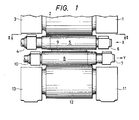
- a material to be rolled can be rolled in an improved form if the working rolls are moved and set so that the roll shoulders of the upper and lower working rolls 5, 8 substantially conform with the ends of the sheet width of the material 9 to be rolled.
- the working rolls are driven by driving apparatus comprising motors or the like and this driving force is transmitted to the material 9 to be rolled and to the backup rolls 2, 12.
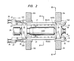
- Figure 2 illustrates an example of the working roll moving mechanism of the invention.
- the working roll 5 is supported by the metal chocks 4, 6 and is driven by the driving apparatus, not shown, through a coupling 26.
- This working roll 5 is supported on both sides by beams 18, 19 that are guided and supported by supports 141, 142 that are secured to stands 131, 134 and by supports 231, 232 that are secured to stands 132, 133, respectively.
- the working roll 8 also is supported by the stands 131, 134, 132, 133 through beams 30, 31 and the supports 141, 142, 231, 232, in the same way as the working roll 5.
- the stands 131 to 134 forms a roll housing.
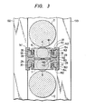
- each of the supports 141, 142 has an upper projection 151, a low projection 152 spaced vertically from the upper projection 151, and a central projection 153 at an equidistant position from the upper and lower projections 151, 152. All the projections extend toward the working rolls 5, 8.
- Each of the upper and lower projections 151, 152 is formed with a recess 154 facing the central projection 153.
- the central projection has at its end 155 small upward and downward extension so that a pair of spaces are formed in which the beams 18, 31 are slidably held.
- the end 155 has a vertical flat face 156 facing the working rolls 5, 8.
- each of the beams 18, 31, that are formed a vertical flat face 161 facing the working roll 5, 8 respectively, a recess 162 formed on a bottom face contacting with the central projection 153 and engaging with one extension of the central projection 153, and a small projection 163 inserted in a recess 154 of the upper or lower projection 151, 152 respectively.
- the vertical flat faces 161 of the beams 18, 31 are aligned with the vertical flat faces 156 of the supports 141, 142 so that guide faces is formed for the metal chocks 6, 7.
- the supports 141, 142 that guide and support the beams 18, 19, 30, 31 are made in a form which wraps or encloses the beams and restrains them against horizontal and torsional deflections.
- these supports 141, 142 are formed as a unitary body, but they may of course, be formed separately.
- Hydraulic cylinders 29 for roll benders which comprise cylinders, pistons 35, covers 38 and so forth are disposed between the metal chocks 6, 7, (4, 10) and the beams 18, 19, 30, 31. All the cylinders are similar to each other; each is disposed in a recess in its beam and the piston 35 is inserted in the cylinder. Each piston 35 has a rod extending through the hole of a cover 28 and engaging a portion of the chock projecting laterally over the beam.
- cylinders 25 serving as axial adjustment actuators are fitted to the beams 18, 19 by covers 27 and are connected by pins 24 to the fixed supports 231, 232 at the side of the roll driving apparatus so that a space enough to accommodate the coupling 26, driving apparatus etc. can be provided therebetween. Therefore, the couplings 26, etc. can be easily connected or disconnected. Further, even if a coupling, for example, is disconnected from its working roll and displaced somewhat from its operative position for some reason, the beams 18, 19, 30, 31 are not damaged by a contact with it.
- the working roll 5 is connected to the beams 18,19 by an arm 16, which extends from the metal chock 6, clamped and fixed to a slit portion 33 of the beams by means of plates 32 with bolts 15 and washers 17.
- This arm 16 may of course be movably connected to the cylinder.
- the working roll 5 can be moved in the axial direction of the roll by axially moving the beams 18, 19 with the cylinders 25 being operated to exert the displacing force.
- the working roll 8 also can be moved in a similar manner to that of the working roll 5 in the opposite direction.
- hollow liquid introduction conduits 21, indicated by dotted lines in Figure 2 are bored through the centers of beams 18, 19, 30, 31 and liquid is pressure-fed into these bores from inlet openings 22.
- the liquid such as cooling water
- the nozzles 20 are disposed near the portions of the working rolls contacting the material to be rolled so that heat conducted to the working rolls can be removed effectively, that is, before the heat reaches deep into the working rolls.
- the working roll 5 supported by beams 18, 19 and the metal chock 6 move together with each other, and so also do the working roll 8 supported by the beams 30, 31, and the metal chock 7 similarly, while the bending force applied to the working rolls is applied by the cylinders 29 incorporated in the beams.
- the bender force is applied to the working rolls during their movement this will not damage the pistons 35 even though a force is being also applied to the backup rolls 2, 12 from the cylinders 29 through the working rolls 5, 8.
- preparation can be made for procedures such as the movement of the working rolls and the like until subsequent rolling without reducing the speed of rotation of the backup rolls even when moving the working rolls axially.
- the beams 18,19 can also cool the working rolls 5. Accordingly, the embodiment of the invention illustrated can provide a compact moving working roll form of rolling mill and can provide a significant effect in improving the efficiency of rolling.
Landscapes
- Engineering & Computer Science (AREA)
- Mechanical Engineering (AREA)
- Metal Rolling (AREA)
- Reduction Rolling/Reduction Stand/Operation Of Reduction Machine (AREA)
Claims (7)
Applications Claiming Priority (2)
| Application Number | Priority Date | Filing Date | Title |
|---|---|---|---|
| JP56086241A JPS57199505A (en) | 1981-06-03 | 1981-06-03 | Work roll moving type rolling mill |
| JP86241/81 | 1981-06-03 |
Publications (4)
| Publication Number | Publication Date |
|---|---|
| EP0067040A2 EP0067040A2 (fr) | 1982-12-15 |
| EP0067040A3 EP0067040A3 (en) | 1983-06-15 |
| EP0067040B1 true EP0067040B1 (fr) | 1986-09-10 |
| EP0067040B2 EP0067040B2 (fr) | 1996-04-03 |
Family
ID=13881303
Family Applications (1)
| Application Number | Title | Priority Date | Filing Date |
|---|---|---|---|
| EP82302863A Expired - Lifetime EP0067040B2 (fr) | 1981-06-03 | 1982-06-03 | Laminoir |
Country Status (4)
| Country | Link |
|---|---|
| US (1) | US4491005A (fr) |
| EP (1) | EP0067040B2 (fr) |
| JP (1) | JPS57199505A (fr) |
| DE (1) | DE3273146D1 (fr) |
Families Citing this family (21)
| Publication number | Priority date | Publication date | Assignee | Title |
|---|---|---|---|---|
| DE3331055C2 (de) * | 1983-08-29 | 1994-11-03 | Schloemann Siemag Ag | Walzgerüst mit axial verschieblichen Arbeitswalzen |
| DE3419261C3 (de) * | 1984-05-23 | 1994-12-15 | Achenbach Buschhuetten Gmbh | Walzenkühl- und/oder Schmiervorrichtung für Kaltbandwalzwerke, insbesondere Feinbandwalzwerke |
| DE3521180C2 (de) * | 1985-02-08 | 1994-12-01 | Schloemann Siemag Ag | Vorrichtung zum axialen Verschieben von Walzen in Walzgerüsten |
| DE3529364A1 (de) * | 1985-08-16 | 1987-02-19 | Schloemann Siemag Ag | Antriebsvorrichtung zur axialen verschiebung von walzen eines walzgeruestes |
| GB8528848D0 (en) * | 1985-11-22 | 1985-12-24 | Davy Mckee Poole | Rolling mills |
| DE3769809D1 (de) * | 1986-01-17 | 1991-06-13 | Schloemann Siemag Ag | Staenderfeste biegevorrichtung fuer axial verschiebbare walzen eines mehrwalzengeruestes. |
| FR2594359B1 (fr) * | 1986-02-14 | 1988-06-10 | Clecim Sa | Procede de reglage du profil de cylindres deplacables dans un laminoir et laminoir perfectionne pour la mise en oeuvre du procede |
| JPH0749124B2 (ja) * | 1986-03-20 | 1995-05-31 | 株式会社日立製作所 | ロールシフト式圧延機 |
| DE3627690A1 (de) * | 1986-08-14 | 1988-02-25 | Schloemann Siemag Ag | Biege- und ausbalanciervorrichtung fuer axial verschiebbare arbeitswalzen eines quartowalzgeruestes |
| DE3627692A1 (de) * | 1986-08-14 | 1988-02-25 | Schloemann Siemag Ag | Biege- und ausbalanciervorrichtung fuer axial verschiebbare arbeitswalzen eines quartowalzgeruestes |
| FR2611541B1 (fr) * | 1987-02-27 | 1994-04-29 | Clecim Sa | Dispositif de reglage du profil et de repartition d'usure de cylindres dans un laminoir a cylindres deplacables axialement |
| FR2617744B1 (fr) * | 1987-07-08 | 1994-05-20 | Clecim | Procede et installation de planage d'une bande metallique |
| DE3822821A1 (de) * | 1988-07-06 | 1990-01-18 | Schloemann Siemag Ag | Walzwerk zur herstellung eines walzgutes |
| US5165266A (en) * | 1991-11-04 | 1992-11-24 | International Rolling Mill Consultants, Inc. | Chockless roll support system |
| DE4309986A1 (de) * | 1993-03-29 | 1994-10-06 | Schloemann Siemag Ag | Verfahren und Vorrichtung zum Walzen eines Walzbandes |
| IT1297585B1 (it) * | 1997-12-24 | 1999-12-17 | Danieli Off Mecc | Blocco di curvatura per gabbia di laminazione a quarto |
| US5970771A (en) * | 1998-07-10 | 1999-10-26 | Danieli United | Continuous spiral motion system for rolling mills |
| US5956990A (en) * | 1998-08-14 | 1999-09-28 | Danieli United | Apparatus and method for producing and handling superlarge coils of metal strip |
| US6415489B1 (en) * | 1999-07-29 | 2002-07-09 | Morgan Construction Company | Hydraulically actuated tool for mounting and dismounting rolling mill roll neck bearings |
| EP1184094A3 (fr) * | 2000-08-29 | 2004-12-22 | Hitachi, Ltd. | Laminoir et procédé de laminage |
| JP5644418B2 (ja) * | 2010-11-24 | 2014-12-24 | 株式会社Ihi | ロールプレス装置 |
Family Cites Families (12)
| Publication number | Priority date | Publication date | Assignee | Title |
|---|---|---|---|---|
| CH320274A (fr) * | 1955-02-19 | 1957-03-31 | Norton Co Ltd Sir James Farmer | Machine à calandrer |
| GB1351074A (en) * | 1971-02-15 | 1974-04-24 | Hitachi Ltd | Rolling mills |
| JPS517635B2 (fr) * | 1971-12-10 | 1976-03-09 | ||
| US3943742A (en) * | 1973-08-24 | 1976-03-16 | Hitachi, Ltd. | Rolling mill |
| GB1433301A (en) * | 1974-02-19 | 1976-04-28 | Loewy Robertson Eng Co Ltd | Tension bridle for a rolling mill |
| BE842903A (fr) * | 1976-06-11 | 1976-10-01 | Centre Rech Metallurgique | Procede et dispositif pour le refroidissement des cylindres a cannelures |
| JPS5312753A (en) * | 1976-07-23 | 1978-02-04 | Hitachi Ltd | Roll shaft moving resistance decreasing device |
| JPS5483658A (en) * | 1977-12-16 | 1979-07-03 | Hitachi Ltd | Cooler for reducing roll |
| JPS6047005B2 (ja) * | 1978-03-01 | 1985-10-19 | 住友金属工業株式会社 | 熱間圧延油噴射方法 |
| JPS6040928B2 (ja) * | 1978-08-09 | 1985-09-13 | 株式会社日立製作所 | 圧延機 |
| JPS5666307A (en) * | 1979-10-04 | 1981-06-04 | Hitachi Ltd | Rolling mill |
| JPS56136207A (en) * | 1980-03-28 | 1981-10-24 | Nippon Steel Corp | Multistage rolling mill |
-
1981
- 1981-06-03 JP JP56086241A patent/JPS57199505A/ja active Granted
-
1982
- 1982-06-03 DE DE8282302863T patent/DE3273146D1/de not_active Expired
- 1982-06-03 EP EP82302863A patent/EP0067040B2/fr not_active Expired - Lifetime
- 1982-06-03 US US06/384,557 patent/US4491005A/en not_active Expired - Lifetime
Also Published As
| Publication number | Publication date |
|---|---|
| EP0067040B2 (fr) | 1996-04-03 |
| DE3273146D1 (en) | 1986-10-16 |
| JPS6355368B2 (fr) | 1988-11-02 |
| US4491005B1 (fr) | 1991-01-08 |
| EP0067040A3 (en) | 1983-06-15 |
| JPS57199505A (en) | 1982-12-07 |
| US4491005A (en) | 1985-01-01 |
| EP0067040A2 (fr) | 1982-12-15 |
Similar Documents
| Publication | Publication Date | Title |
|---|---|---|
| EP0067040B1 (fr) | Laminoir | |
| EP0094104B1 (fr) | Laminoir et méthode pour laminer des tôles | |
| US4499748A (en) | Rolling mill | |
| KR100245472B1 (ko) | 압연기 및 압연방법 및 압연설비 | |
| US3171305A (en) | Rolling mill | |
| US20110132055A1 (en) | Rolling device | |
| CA2738713C (fr) | Dispositif de laminage | |
| US4058154A (en) | Guiding and supporting means for continuously cast metal strand | |
| US6354128B1 (en) | Method to eliminate the play between chocks and relative support blocks in four-high rolling stands and relative device | |
| US4614103A (en) | Rolling mill | |
| EP0744227B1 (fr) | Dispositif de croisement de cylindres pour un laminoir | |
| EP1125659B1 (fr) | Procédé de réglage de la position axiale des billettes sortant de la coulée continue et dispositif connexé s'y rapportant | |
| US6029491A (en) | Continous spiral motion and roll bending system for rolling mills | |
| JPS6076209A (ja) | 支持ローラにより支持されるワークロールを備えた六重式圧延機のロールスタンド | |
| EP1005921B1 (fr) | Laminoir à cylindres obliques | |
| JP7352746B2 (ja) | 圧延装置 | |
| US8051895B2 (en) | Operating method for twin-roll casting machine, and side weir supporting device | |
| EP3911454B1 (fr) | Système de cintrage et de déplacement pour cages de laminoir | |
| US3702557A (en) | Apparatus for supporting yokes for a rolling mill having roll contour control | |
| KR101151248B1 (ko) | 롤 스탠드 | |
| US3373589A (en) | Roll bending device for rolling mill | |
| US20100024506A1 (en) | Roller device | |
| US5911782A (en) | Compensation device for chocks in four-high rolling mill stands with crossed displacement of the rolls | |
| CN101282796A (zh) | 弯辊装置 | |
| JPS6013546Y2 (ja) | 鋼板矯正用ロ−ラ−レベラ− |
Legal Events
| Date | Code | Title | Description |
|---|---|---|---|
| PUAI | Public reference made under article 153(3) epc to a published international application that has entered the european phase |
Free format text: ORIGINAL CODE: 0009012 |
|
| 17P | Request for examination filed |
Effective date: 19820719 |
|
| AK | Designated contracting states |
Designated state(s): CH DE FR GB IT LI NL SE |
|
| PUAL | Search report despatched |
Free format text: ORIGINAL CODE: 0009013 |
|
| AK | Designated contracting states |
Designated state(s): CH DE FR GB IT LI NL SE |
|
| RBV | Designated contracting states (corrected) |
Designated state(s): DE FR GB IT |
|
| GRAA | (expected) grant |
Free format text: ORIGINAL CODE: 0009210 |
|
| AK | Designated contracting states |
Kind code of ref document: B1 Designated state(s): DE FR GB IT |
|
| REF | Corresponds to: |
Ref document number: 3273146 Country of ref document: DE Date of ref document: 19861016 |
|
| ITF | It: translation for a ep patent filed | ||
| ET | Fr: translation filed | ||
| PLBI | Opposition filed |
Free format text: ORIGINAL CODE: 0009260 |
|
| PLBI | Opposition filed |
Free format text: ORIGINAL CODE: 0009260 |
|
| PLBI | Opposition filed |
Free format text: ORIGINAL CODE: 0009260 |
|
| 26 | Opposition filed |
Opponent name: SMS SCHLOEMANN-SIEMAG AG Effective date: 19870604 |
|
| 26 | Opposition filed |
Opponent name: SOCIETE CLECIM Effective date: 19870609 |
|
| 26 | Opposition filed |
Opponent name: DAVY MCKEE (SHEFFIELD) LIMITED Effective date: 19870608 |
|
| ITTA | It: last paid annual fee | ||
| PUAH | Patent maintained in amended form |
Free format text: ORIGINAL CODE: 0009272 |
|
| STAA | Information on the status of an ep patent application or granted ep patent |
Free format text: STATUS: PATENT MAINTAINED AS AMENDED |
|
| 27A | Patent maintained in amended form |
Effective date: 19960403 |
|
| AK | Designated contracting states |
Kind code of ref document: B2 Designated state(s): DE FR GB IT |
|
| ET3 | Fr: translation filed ** decision concerning opposition | ||
| ITF | It: translation for a ep patent filed | ||
| PGFP | Annual fee paid to national office [announced via postgrant information from national office to epo] |
Ref country code: GB Payment date: 20010525 Year of fee payment: 20 Ref country code: FR Payment date: 20010525 Year of fee payment: 20 |
|
| PGFP | Annual fee paid to national office [announced via postgrant information from national office to epo] |
Ref country code: DE Payment date: 20010629 Year of fee payment: 20 |
|
| REG | Reference to a national code |
Ref country code: GB Ref legal event code: IF02 |
|
| PG25 | Lapsed in a contracting state [announced via postgrant information from national office to epo] |
Ref country code: GB Free format text: LAPSE BECAUSE OF EXPIRATION OF PROTECTION Effective date: 20020602 |
|
| REG | Reference to a national code |
Ref country code: GB Ref legal event code: PE20 Effective date: 20020602 |
|
| APAH | Appeal reference modified |
Free format text: ORIGINAL CODE: EPIDOSCREFNO |