EP0067089A1 - Beleuchtungskontrollanlage mit Speicher - Google Patents
Beleuchtungskontrollanlage mit Speicher Download PDFInfo
- Publication number
- EP0067089A1 EP0067089A1 EP82400876A EP82400876A EP0067089A1 EP 0067089 A1 EP0067089 A1 EP 0067089A1 EP 82400876 A EP82400876 A EP 82400876A EP 82400876 A EP82400876 A EP 82400876A EP 0067089 A1 EP0067089 A1 EP 0067089A1
- Authority
- EP
- European Patent Office
- Prior art keywords
- lighting
- light
- battery
- signaling
- lamps
- Prior art date
- Legal status (The legal status is an assumption and is not a legal conclusion. Google has not performed a legal analysis and makes no representation as to the accuracy of the status listed.)
- Granted
Links
Images
Classifications
-
- H—ELECTRICITY
- H05—ELECTRIC TECHNIQUES NOT OTHERWISE PROVIDED FOR
- H05B—ELECTRIC HEATING; ELECTRIC LIGHT SOURCES NOT OTHERWISE PROVIDED FOR; CIRCUIT ARRANGEMENTS FOR ELECTRIC LIGHT SOURCES, IN GENERAL
- H05B47/00—Circuit arrangements for operating light sources in general, i.e. where the type of light source is not relevant
- H05B47/20—Responsive to malfunctions or to light source life; for protection
- H05B47/28—Circuit arrangements for protecting against abnormal temperature
Definitions
- the present invention relates to a memory device for lighting control. It applies in particular to the control of the lighting of public telephone booths which are connected to the public lighting network triggered at dusk and extinguished when it rises.
- the lighting on and off control can be carried out by a day / night clock or by a photocell sensitive to natural lighting, depending on the location.
- the present invention also applies to the control of the lighting of lampposts, showcases and light sources for signaling or security.
- the object of the present invention is to remedy this drawback.
- the device which is the subject of the invention therefore makes it possible to control "off-line" the correct functioning of a lighting which can be automatically or remotely controlled and for example provided for the night period, without the need to go on site during the period of operation and without remote information transmission.
- the (or said) lighting means (s) to be controlled can (can) be provided (s) to operate for one or more time intervals.
- the lighting can be periodic (case of public lighting) or not.
- said storage means further comprises a thermistor with a negative temperature coefficient provided for optimizing the charge of said accumulator means as a function of the ambient temperature.
- Accumulators are indeed very sensitive to it.
- the addition of said thermistor to the device which is the subject of the invention makes it possible to hope, for the accumulator means, a longer service life than that which they would have without this thermistor.
- said signaling means comprise a light source provided for emitting light after operation of said lighting means.
- This light source can be a light emitting diode.
- Said electric current accumulator means can thus charge when the lighting is on and discharge, when the latter is off, in said diode. The lighting of the latter then testifies a posteriori of the proper functioning of the lighting to be checked.
- the device which is the subject of the invention, it also comprises a clock and counting means, provided for interrupting said signaling after a determined time. It is thus possible to limit the discharge time of the means for accumulating electric current in the event of failure of the lighting means and to avoid damaging these means. Accumulators.
- the device which is the subject of the invention can also be applied to the control of the operation of an appliance, this appliance being associated with a light source so that the latter works if and only if said appliance works or has worked. We are thus brought back to the control of this light source.
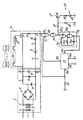
- This embodiment comprises, first of all, a stabilized DC power supply 2 .
- This power supply 2 comprises a transformer 3 whose primary 4 is for example connected to the AC 220 V sector which can also be used to supply the lamps 1 with current.
- the secondary 5 of the transformer 3 supplies a rectifier bridge 6, for example of the GRAETZ bridge type, which itself supplies a first electrical resistance 7, making it possible to reduce the voltage at the output of the rectifier bridge 6, filtering means constituted by a electrolytic capacitor 8 and another capacitor 9, and a voltage stabilizing Zener diode 10.
- the power supply 2 is thus stabilized and capable of delivering a direct current and has a first output terminal B 1 at a positive potential and a second output terminal B 2 at a zero potential. These two terminals correspond to those of the Zener diode 10.
- the device according to the invention shown in the appended drawing also includes means 11 for storing information on the correct operation of the lamps 1.
- These means 11 for storing comprise a storage battery 12, a transistor 13 of the NPN type, phototransistors 14 the number of which is equal to that of the lamps 1, each of them being associated with one of these lamps 1 and arranged to receive the light that this lamp is capable of emitting when it operates, a thermistor 15 with coefficient negative temperature, a diode 16 and a second electrical resistance 17.
- the NPN transistor 13 is connected by its collector to the first terminal B 1 and by its emitter to the second electrical resistance 17.
- the latter intended to optimize the charging current of the storage battery 12, is connected to a diode 16, itself connected to this storage battery 12 by the positive pole P thereof, the negative pole N of the battery 12 being connected to the second output terminal B 2 of the supply 2 and put by elsewhere grounded.
- the diode 16 is mounted so as to be reverse biased with respect to the battery 12.
- the phototransistors 14 are connected in series: the emitter of one is connected to the collector of the next, and so on.
- the collector of the first phototransistor in the series obtained is connected to the first output terminal B1 of power supply 2 and the emitter of the last phototransistor of this series is connected to the base of transistor 13 of NPN type, via thermistor 15 with negative temperature coefficient.
- the device according to the invention shown also includes a clock 18 and counting means or counter 19.
- the clock 18 is for example produced, in a known manner in the state of the art. that, using two NOR gates 18a and 18b, a fixed resistor 18c, an adjustable resistor 18d, provided so that the frequency of the clock 18 is adjustable, and a capacitor 18e.
- the counter 19 is of the kind sold by MOTOROLA under the reference MC 14521 (CMOS integrated circuit counters).
- a first input 19a of the counter 19, corresponding to the resetting of the latter, is connected to a point S taken between the second resistor 17 and the diode 16.
- An output 19b of the counter 19 is connected to an input E1 of a first NOR gate 20 whose other input E 2 is connected to said point S.
- the output of this first gate 20 is connected to the two inputs of a second NOR gate 21 whose output is connected to the input of l clock 18.
- the output of this clock 18 is connected to a second input 19c of the counter 19.
- the latter is also connected, respectively by two terminals 19d and 19e, to the positive pole P of the battery 12 and to ground, so as to be supplied with electric current.
- the battery 12 supplies (in a manner not shown) with electric current the four NOR doors 18a, 18b, 20 and 21.
- a third electrical resistance 22 is, on one side, connected to ground and, on the other, to the other input E 2 of the first NOR gate 20, to fix the potential of this other input E 2 .
- the device according to the invention shown finally comprises signaling means 23 comprising a light-emitting diode 24 connected to the collector of a PNP-type transistor 25 by means of a fourth electrical resistance 26 provided for limiting the current in the light-emitting diode 24.
- the emitter of the PNP type transistor 25 is connected to the positive pole P of the battery 12.
- the light-emitting diode 24 is also connected to ground and of course mounted so as to be polarized in direct relation to the battery 12 when the PNP transistor 25 conducts the electric current.
- the base of this PNP type transistor 25 is connected, via a fifth electrical resistor 27 provided for the biasing of this transistor, to the output of the second NOR gate 21.
- a sixth resistor 28 also provided for the bias of the PNP type transistor 25 is mounted between the positive pole P of the battery 12 and a point between the fifth resistor 27 and the base of the PNP type transistor 25.
- the particular embodiment of the device which is the subject of the invention, shown in the accompanying drawing, makes it possible to control several lamps 1, using several phototransistors 14 mounted in such a way that the light-emitting diode 24 is only lit if all of the 1 lamps to control worked. (The mounting of the phototransistors 14 was indicated previously). Of course, said embodiment could include only a phototransistor 14 if there was only one lamp 1 to be checked.
- the input of the clock 18 and the base of the PNP transistor 25 are therefore also brought to a high voltage level. Consequently, the clock 18 is blocked and the PNP-type transistor 25 is also blocked, which causes the light-emitting diode 24 (supposed to have been lit during the previous day) to go out and the discharge of the battery 12 to stop. this light emitting diode 24.
- the light-emitting diode 24 therefore lights up (thus testifying to the proper functioning of the lamps 1 during the previous night), since the battery 12 can then discharge there.
- the diode 16 makes it possible to prevent the discharge of the battery 12 from taking place in the direction of the transistor 13 of the NPN type and also makes it possible to prevent the said point S from being permanently at a positive potential).
- the battery 12 is recharged and so on. If at least one of the lamps 1 does not come back on, due to a power failure or a malfunction of this lamp, the battery 12 continues to discharge for a certain time. At the end of a determined number of pulses (corresponding for example to 20 hours of discharge), the output 19b of the counter 19 is brought to logic level 1. It is therefore the same for the input E 1 of the first gate 20 and, consequently, for the exit from the second door 21, therefore for the entry of the clock 18, the latter finding itself blocked. Similarly, the PNP type transistor 25, the base of which is then brought to a high voltage level, is also blocked.
- the light-emitting diode 24 goes out and the battery 12 ceases to discharge and therefore does not drain completely, which would have a detrimental effect on its service life.
- Counter 19 is reset to zero.
- Electrolytic capacitor 8 100 ⁇ F.
- Other capacitor 9 10 nF 18th clock capacitor 18: 0.1 ⁇ F Maximum voltage tolerable by these three capacitors 8, 9 and 18th: 25 V.
- Phototransistors 14, transistor 13 of NPN type and transistor 25 of PNP type are of the type which have BP103B, 2N2222 and BC179 respectively.
- the transformer 3 is for example designed to give 12 V alternating to the secondary 5, when the primary 4 is connected to the mains (220 V alternating).
- the power of this transformer 3 is for example 3 VA.
- the Zener diode 10 is for example provided for stabilizing the voltage at 8V between its terminals B 1 and B 2 and the storage battery 12 is for example a miniature storage battery with cadmium-nickel, the capacity of which is approximately 500 milliamps . hour and which, when charged, has a voltage of 5V between its terminals.
- the thermistor 15 with a negative temperature coefficient having for example a resistance of 16 k ⁇ at 20 ° C., makes it possible to optimize the charge of the battery 12 as a function of the ambient temperature at. which the accumulators are very sensitive. Its addition to the device according to the invention makes it possible to hope for the battery 12 given in the example above, a lifetime of the order of 2000 cycles (charges - discharges), or approximately 6 years, at the rate of a cycle per 24 hours.
- the charge-discharge energy balance corresponds, for a discharge of the accumulator to 60%, to 6 charging hours (lamp lighting period 1), which is a minimum for public lighting in the summer period, and at 20 hours of discharge (period lamps 1), which gives plenty of time to carry out the check.
- the sum of these two durations (6 hours and 24 hours) being greater than 24 hours, there is no uncertainty: if the light-emitting diode 24 is lit during the control, it is that the lamps 1 have operated for the ignition period.
- the battery 12 can be incompletely charged and, depending on the moment of observation, the light-emitting diode 24 can be lit or not. When the lighting fault is clear, the light-emitting diode will certainly be extinguished during the next observation.
- the device according to the invention which has been described, can be placed in a box whose dimensions can be of the order of 10 ⁇ 7 ⁇ 5 cm.
- the photodetector (s) 14 as well as the light-emitting diode 24 can be integrated into this housing or dissociated from it. Of course, several photodetectors 14 could be used per lamp 1.
- the device according to the invention which therefore allows "offline” control of lighting means, can, depending on its cost and according to the importance attached to the monitoring of these lighting means, be used permanently or occasionally, depending on the reliability of the lighting means monitored.
Landscapes
- Circuit Arrangement For Electric Light Sources In General (AREA)
Applications Claiming Priority (2)
| Application Number | Priority Date | Filing Date | Title |
|---|---|---|---|
| FR8109611A FR2506110A1 (fr) | 1981-05-14 | 1981-05-14 | Dispositif a memoire pour controle d'eclairage |
| FR8109611 | 1981-05-14 |
Publications (2)
| Publication Number | Publication Date |
|---|---|
| EP0067089A1 true EP0067089A1 (de) | 1982-12-15 |
| EP0067089B1 EP0067089B1 (de) | 1986-01-02 |
Family
ID=9258439
Family Applications (1)
| Application Number | Title | Priority Date | Filing Date |
|---|---|---|---|
| EP82400876A Expired EP0067089B1 (de) | 1981-05-14 | 1982-05-11 | Beleuchtungskontrollanlage mit Speicher |
Country Status (4)
| Country | Link |
|---|---|
| US (1) | US4507655A (de) |
| EP (1) | EP0067089B1 (de) |
| DE (1) | DE3268243D1 (de) |
| FR (1) | FR2506110A1 (de) |
Cited By (1)
| Publication number | Priority date | Publication date | Assignee | Title |
|---|---|---|---|---|
| WO1990003094A1 (en) * | 1988-09-12 | 1990-03-22 | Tailor Made Systems Limited | Apparatus and device for recording the condition of equipment, such as street lighting, and method of monitoring and servicing street lighting |
Families Citing this family (5)
| Publication number | Priority date | Publication date | Assignee | Title |
|---|---|---|---|---|
| GB2150372B (en) * | 1983-11-25 | 1986-12-10 | Ferranti Plc | Lamp failure detector |
| US5018226A (en) * | 1988-08-19 | 1991-05-28 | William Price Williams | Apparatus and method for transporting an injured person |
| DE19833274C1 (de) * | 1998-07-24 | 1999-10-07 | Deutsche Telekom Ag | Beleuchtungsüberwachung für Telefonhäuschen |
| US10184624B2 (en) * | 2007-05-31 | 2019-01-22 | Tseng-Lu Chien | Multiple functions LED night light |
| DE102005062020A1 (de) * | 2005-12-22 | 2007-01-25 | Daimlerchrysler Ag | Vorrichtung zur Information bei Leuchtenausfall an Fahrzeugen |
Citations (1)
| Publication number | Priority date | Publication date | Assignee | Title |
|---|---|---|---|---|
| US3311779A (en) * | 1963-03-27 | 1967-03-28 | Jr Heinrich Hartkorn | Indicating lamp circuit for the failure of head lamp circuit |
Family Cites Families (4)
| Publication number | Priority date | Publication date | Assignee | Title |
|---|---|---|---|---|
| US3412395A (en) * | 1966-01-14 | 1968-11-19 | Ralph E Kiene Jr | Current actuated switch for cash register |
| US3728705A (en) * | 1970-05-04 | 1973-04-17 | Wagner Electric Corp | Lamp outage indicator |
| US3710367A (en) * | 1970-10-28 | 1973-01-09 | Gen Motors Corp | Lamp failure indicator for a dual-filament lamp |
| US4092642A (en) * | 1976-10-22 | 1978-05-30 | Delphic Limited | Plural sensor monitoring and display device |
-
1981
- 1981-05-14 FR FR8109611A patent/FR2506110A1/fr active Granted
-
1982
- 1982-05-11 US US06/377,011 patent/US4507655A/en not_active Expired - Fee Related
- 1982-05-11 DE DE8282400876T patent/DE3268243D1/de not_active Expired
- 1982-05-11 EP EP82400876A patent/EP0067089B1/de not_active Expired
Patent Citations (1)
| Publication number | Priority date | Publication date | Assignee | Title |
|---|---|---|---|---|
| US3311779A (en) * | 1963-03-27 | 1967-03-28 | Jr Heinrich Hartkorn | Indicating lamp circuit for the failure of head lamp circuit |
Cited By (3)
| Publication number | Priority date | Publication date | Assignee | Title |
|---|---|---|---|---|
| WO1990003094A1 (en) * | 1988-09-12 | 1990-03-22 | Tailor Made Systems Limited | Apparatus and device for recording the condition of equipment, such as street lighting, and method of monitoring and servicing street lighting |
| GB2245358A (en) * | 1988-09-12 | 1992-01-02 | Tailor Made Systems Limited | Apparatus and device for recording the condition of equipment,such as street lighting,and method of monitoring and servicing street lighting |
| GB2245358B (en) * | 1988-09-12 | 1993-02-03 | Tailor Made Systems Limited | Apparatus and device for recording the condition of equipment,such as street lighting,and method of monitoring and servicing street lighting |
Also Published As
| Publication number | Publication date |
|---|---|
| EP0067089B1 (de) | 1986-01-02 |
| US4507655A (en) | 1985-03-26 |
| DE3268243D1 (en) | 1986-02-13 |
| FR2506110A1 (fr) | 1982-11-19 |
| FR2506110B1 (de) | 1984-05-25 |
Similar Documents
| Publication | Publication Date | Title |
|---|---|---|
| EP0110775B1 (de) | Regulierungseinrichtung mit kleiner Verlustspannung | |
| EP0067089B1 (de) | Beleuchtungskontrollanlage mit Speicher | |
| FR2493543A1 (fr) | Appareil a lumiere-eclair electrique | |
| FR2541008A1 (fr) | Systeme pour controler le fonctionnement des transducteurs de sortie d'une unite centrale de commande et de controle pour des machines et/ou des dispositifs utilisables dans des lignes de production et/ou des lignes d'emballage de produits | |
| FR2695286A1 (fr) | Système de détection et de signalisation de lampes défaillantes dans un réseau d'éclairage. | |
| EP0393774B1 (de) | Überwachungsschaltung und mit einer solchen Schaltung ausgerüstete Datenübertragungseinrichtung | |
| FR2521771A1 (fr) | Circuit d'alimentation d'un contact de commande et son application a la commande d'une temporisation de repos d'un relais | |
| EP0080396B1 (de) | Durch integrierte Mikroprozessorschaltung gesteuerte Zweidraht-Vierdraht-Fernsprechübertragungsschaltung und Speisungssicherstellung durch Leitungsstrom | |
| EP0171629B1 (de) | Vorrichtung zur Prüfung der Restkapazität von einem Sicherheitsbeleuchtungsaggregat | |
| FR2808647A1 (fr) | Module electronique de commande d'eclairage configurable | |
| EP0342579A1 (de) | Vorrichtung für den Autonomietest bei Notbeleuchtungsblöcken | |
| EP0418168B1 (de) | Vorrichtung zur Fernüberwachung der Stromversorgung eines elektrischen Gerätes | |
| FR2477282A1 (fr) | Dispositif de controle de la capacite de batteries d'accumulateurs | |
| EP0899934A1 (de) | Anpassungsschaltung Für Versorgungspannung | |
| FR2719947A1 (fr) | Procédé et dispositif d'entretien d'un accumulateur utilisé en marche flottante, notamment pour un appareil de sécurité. | |
| FR2616929A1 (fr) | Dispositif de commande de test d'autonomie pour un ensemble de blocs d'eclairage de securite | |
| FR2533097A1 (fr) | Controleur de ligne telephonique destine a cooperer avec un automate | |
| JP3259214B2 (ja) | バッテリーライト装置 | |
| FR2710205A1 (fr) | Procédé de distribution contrôlée d'énergie et dispositif pour la mise en Óoeuvre du procédé. | |
| FR2535930A1 (fr) | Ensemble portatif autonome pour le controle d'equipement d'eclairage public | |
| EP1177673B1 (de) | Telefonleitungsgespeistes stromversorgungssystem | |
| FR2638585A1 (fr) | Chargeur pour accumulateur cadmium-nickel | |
| FR2802031A1 (fr) | Dispositif bloc autonome d'eclairage de securite et d'alarme et installation utilisant un tel dispositif | |
| WO2026068476A1 (fr) | Systeme de gestion d'un pack batterie pour l'alimentation d'un actionneur en veille | |
| FR2555340A1 (fr) | Centrale d'alarme |
Legal Events
| Date | Code | Title | Description |
|---|---|---|---|
| PUAI | Public reference made under article 153(3) epc to a published international application that has entered the european phase |
Free format text: ORIGINAL CODE: 0009012 |
|
| AK | Designated contracting states |
Designated state(s): DE GB IT SE |
|
| 17P | Request for examination filed |
Effective date: 19830520 |
|
| GRAA | (expected) grant |
Free format text: ORIGINAL CODE: 0009210 |
|
| AK | Designated contracting states |
Designated state(s): DE GB IT SE |
|
| REF | Corresponds to: |
Ref document number: 3268243 Country of ref document: DE Date of ref document: 19860213 |
|
| ITF | It: translation for a ep patent filed | ||
| PLBE | No opposition filed within time limit |
Free format text: ORIGINAL CODE: 0009261 |
|
| STAA | Information on the status of an ep patent application or granted ep patent |
Free format text: STATUS: NO OPPOSITION FILED WITHIN TIME LIMIT |
|
| 26N | No opposition filed | ||
| PG25 | Lapsed in a contracting state [announced via postgrant information from national office to epo] |
Ref country code: SE Effective date: 19870512 |
|
| PG25 | Lapsed in a contracting state [announced via postgrant information from national office to epo] |
Ref country code: DE Effective date: 19880202 |
|
| GBPC | Gb: european patent ceased through non-payment of renewal fee | ||
| PG25 | Lapsed in a contracting state [announced via postgrant information from national office to epo] |
Ref country code: GB Free format text: LAPSE BECAUSE OF NON-PAYMENT OF DUE FEES Effective date: 19881121 |
|
| EUG | Se: european patent has lapsed |
Ref document number: 82400876.7 Effective date: 19880616 |