EP0067096A2 - Deflate-equalizing valve apparatus for inflatable packer formation tester - Google Patents
Deflate-equalizing valve apparatus for inflatable packer formation tester Download PDFInfo
- Publication number
- EP0067096A2 EP0067096A2 EP82400923A EP82400923A EP0067096A2 EP 0067096 A2 EP0067096 A2 EP 0067096A2 EP 82400923 A EP82400923 A EP 82400923A EP 82400923 A EP82400923 A EP 82400923A EP 0067096 A2 EP0067096 A2 EP 0067096A2
- Authority
- EP
- European Patent Office
- Prior art keywords
- inflation
- passage
- extended
- mandrel assembly
- valve
- Prior art date
- Legal status (The legal status is an assumption and is not a legal conclusion. Google has not performed a legal analysis and makes no representation as to the accuracy of the status listed.)
- Granted
Links
Images

Classifications
-
- E—FIXED CONSTRUCTIONS
- E21—EARTH OR ROCK DRILLING; MINING
- E21B—EARTH OR ROCK DRILLING; OBTAINING OIL, GAS, WATER, SOLUBLE OR MELTABLE MATERIALS OR A SLURRY OF MINERALS FROM WELLS
- E21B49/00—Testing the nature of borehole walls; Formation testing; Methods or apparatus for obtaining samples of soil or well fluids, specially adapted to earth drilling or wells
- E21B49/08—Obtaining fluid samples or testing fluids, in boreholes or wells
- E21B49/087—Well testing, e.g. testing for reservoir productivity or formation parameters
-
- E—FIXED CONSTRUCTIONS
- E21—EARTH OR ROCK DRILLING; MINING
- E21B—EARTH OR ROCK DRILLING; OBTAINING OIL, GAS, WATER, SOLUBLE OR MELTABLE MATERIALS OR A SLURRY OF MINERALS FROM WELLS
- E21B33/00—Sealing or packing boreholes or wells
- E21B33/10—Sealing or packing boreholes or wells in the borehole
- E21B33/12—Packers; Plugs
- E21B33/124—Units with longitudinally-spaced plugs for isolating the intermediate space
- E21B33/1243—Units with longitudinally-spaced plugs for isolating the intermediate space with inflatable sleeves
- E21B33/1246—Units with longitudinally-spaced plugs for isolating the intermediate space with inflatable sleeves inflated by down-hole pumping means operated by a pipe string
-
- E—FIXED CONSTRUCTIONS
- E21—EARTH OR ROCK DRILLING; MINING
- E21B—EARTH OR ROCK DRILLING; OBTAINING OIL, GAS, WATER, SOLUBLE OR MELTABLE MATERIALS OR A SLURRY OF MINERALS FROM WELLS
- E21B34/00—Valve arrangements for boreholes or wells
- E21B34/06—Valve arrangements for boreholes or wells in wells
- E21B34/12—Valve arrangements for boreholes or wells in wells operated by movement of casings or tubings
- E21B34/125—Valve arrangements for boreholes or wells in wells operated by movement of casings or tubings with time delay systems, e.g. hydraulic impedance mechanisms
Definitions
- This invention relates generally to a drill stem testing system using inflatable packers, and particularly to a new and improved valve system for equalizing pressures across and enabling deflation of the packersduring the course of a well testing operation.
- packer elements of the type that can be inflated by a downhole pump to isolate and seal off the well interval to be tested.
- pressure equalization must be stopped.
- the pressures must again be equalized and the packer elements deflated so that the string of tools can be removed from the well or moved to another test elevation therein.
- valve apparatus adapted for use in connection with a downhole pump that supplies well fluids under pressure to inflatable packers to cause the same to expand and thereby isolate a well interval, characterized by: telescopically arranged mandrel and housing assemblies movable between extended and retracted relative position, said assemblies defining axially extending test and inflation passage; first valve means for communicating said test passage with the well annulus above said inflatable packers when said assemblies are in said extended relative position to maintain pressure equalization during packer element inflation; second valve means for communicating said inflation passage the well annulus above said inflatable packers when said'assemblies are in said extended relative position to enable packer element deflation; and third valve means responsive to the outlet pressure of said pump for preventing packer element deflation when said pump is being operated with said assemblies in said extended relative position even though said second valve means is open.
- Fig. 1 for a schematic illustration of the entire string of drill stem testing tools disposed in a well to be tested, the running-in string 10 of drill pipe or tubing is provided with a reverse circulating valve 11 of any typical design, for example, as shown in U.S. Patent No. 2,863,511.
- a suitable length of pipe 12 is connected between the reversing valve 11 and a multi-flow evaluator or test valve assembly 13 that functions to alternately flow and shut-in the formation interval to be tested.
- a preferred form of test valve is shown in Nutter U.S. Patent No. 3,308,887, assigned to the assignee of this invention.
- the lower end of the test valve 13 is connected to a recorder carrier 14 that houses a pressure recorder of the type shown in the assignee's U.S. Patent No.” 2,816,440, the recorder functioning to make a permanent record of fluid pressure versus elapsed time as the test proceeds.
- the recorder carrier 14 is connected to the upper end of a screen sub 15 through which well fluids are taken in during operation of a packer inflation pump assembly 16 connected to the lower end thereof.
- the pump assembly 16 is disclosed in Upchurch application S.N. , now Patent No. , also assigned to the assignee of this invention. The disclosure of the said Upchurch application is incorporated herein by reference.
- Other rotary pumps such as the device shown in the above-mentioned Conover patent, or the -Evans et al Patent No. 3,926,254, could also be used.
- the lower end on the pump assembly 16 is connected to a pressure equalizing and packer deflating valve apparatus 17 that is constructed in accordance with the present invention.
- the valve 17 is coupled to the upper end of a straddle-type inflatable packer system that includes an upper packer element 18 and a lower packer element 18' that are connected together by an elongated spacer sub 19.
- the packer elements 18 and 18' each include an internally reinforced elastomeric sleeve that normally is retracted but which can be expanded outwardly by applied internal pressure into sealing contact with the surrounding well wall.
- the length of the spacer pipe 19 is selected such that during a test the upper packer 18 is above the upper end of the formation interval of interest, and the lower packer 18' is below the lower end of the interval.
- the lower end of the packer system is connected to the upper end of a deflate-drag spring tool 20 of the type disclosed in the aforementioned Upchurch application.
- the drag springs 21 associated with the tool 20 are bowed outwardly and frictionally engage the walls of the well bore to enable the relative rotation that is necessary to operate the pump assembly 16.
- Another recorder carrier 22 can be connected to the lower end of the drag spring tool 20 and houses pressure recorders that are arranged to measure directly the formation fluid pressure in the isolated interval. A comparison of the data recorded by this instrument with that recorded by the upper instrument 14 can indicate whether or not test passages and ports have been plugged or blocked by debris or the like during the test.
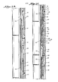
- FIGS. 2A-2C for an illustration of structural details of the deflate-equalizing valve 17, the lower end of the rotary pump housing 30 is connected by a collar 31 to the upper sub 32 of a mandrel assembly indicated generally at 33 that is telescopically disposed within a generally tubular housing 34.
- the mandrel assembly 33 includes a spline section 35 that has outwardly directed splines 36 which mesh with inwardly directed splines 37 on the upper end section 38 of the housing 34 to prevent relative rotation while enabling limited longitudinal relative movement.
- a hydraulic delay system includes a metering piston 40 that is movably mounted on a thickened portion 41 of an intermediate section 42 of the mandrel assembly, with the piston being sized to provide for a restricted leakage of hydraulic fluid contained in an annular chamber 43 from above the piston to below same during upward movement.
- the piston 40 can move away from an annular valve seat 44 during downward movement of the mandrel within the housing so that hydraulic fluid can pass freely through external grooves (not shown) in the mandrel section 41 behind the metering piston.
- the chamber 43 is closed at its upper end by a seal ring 45 and at its lower end by a floating balance piston 47 whose lower face is subjected to the pressure of fluids in the well annulus by one or more ports 48 extending through the wall of the cylinder section 50 of the housing 34.
- the balance piston 47 which carries inner and outer seal rings 51, 52, functionois to transmit the pressure of well fluids to the hydraulic fluid below the piston 40 so that pressure in this region of the chamber is never less than the hydrostatic head pressure in the well bore outside the housing 34.
- An elongated flow tube 54 that is fixedly mounted within the mandrel assembly 33 has a central bore 55 that provides an upwardly extending passage for formation fluids that are recovered during the test.
- the outer periphery of the tube 54 is spaced inwardly of the inner wall surface of the mandrel assembly 33 to provide an inflation passage 56 that leads from the'outlet ports 57 of the rotary pump 16 to the respective interiors of the packer assemblies 18 and 18'.
- the lower end portion of the flow tube 54 has one or more relief passage slots 58 that are disposed below the seals 60 of a sleeve 61 that is fixed within the housing 34 when the mandrel assembly 33 is telescoped downwardly to its lower position therein, and which are disposed above the seals 60 when the mandrel assembly is extended with respect to the housing.
- a valve section 62 of the housing 34 that is connected to the lower end of the cylinder section 50 has a seat sleeve 63 mounted therein.
- the sleeve 63 is sealed with respect to the mandrel section 42 and the section 50 by O-rings 64 and 65, and one or more inflation ports 66 extend laterally through the wall thereof intermediate its ends.
- the lower end portion 67 of the mandrel 42 constitutes a sleeve valve having circumferentially spaced, longitudinally extending flow grooves 68 located adjacent its lower end.
- a second valve sleeve 70 is mounted for independent vertical movement with respect to the seat sleeve 63 and mandrel portion 67, and has a reduced diameter upper section 80 that is sealed with respect to the portion 67 by an O-ring 81, and an enlarged diameter lower section 82 that is sealed with respect to the seat sleeve by 0-ring 83.
- a small diameter port (not shown) can be provided near the lower end of the seat sleeve 63 for purposes to be described hereinafter.
- the annular region 85 outside the seat sleeve 63 is communicated with a lower continuation 86 of the packer inflation passage by several vertical ports 87 indicated in phantom lines in Figure 2C.
- Radially offset from the ports 87 and formed in the same sub 88 is an equalizing port 89 that communicates with an interior space 90 within the housing.
- the string of testing tools is assembled end- to-end generally as shown in the drawings and run into the well bore.
- the drag springs 21 frictionally engage the walls of the bore hole to afford a degree of restraint to vertical as well as rotational movement.
- the pipe string 10 is either empty of fluids, or may contain a column of water to act as a cushion as will be apparent to those skilled in the art.
- the interior of the pipe string 10 provides a low pressure region which can be communicated with an isolated interval of the well to induce formation fluids to flow from the formation into the pipe string if they are capable of so doing.
- the interval is isolated by inflating the elements 18 and 18' into sealing contact with the well wall through operation of the pump assembly 16. This is accomplished by rotating the pipe string 10 to the right to cause the pump to intake well fluids from the annulus via the screen 15 and to exhaust same under pressure to the inflation passage 56.
- the mandrel assembly 33 will be in its extended position with respect to the housing 34 where the pressure relief slots 58 are located above the seals 60 so that the test passage 55 is in communication with the well annulus above the upper packer element via the space 90 and the lower port 89.
- Fluid pressure in the inflation passage 56 will act upwardly on the lower section 82 of the valve sleeve to shift it upwardly to a position where the seals 83 are above the port 66 to enable inflation fluids to pass downwardly through the annular region 85, the vertical ports 87 and the continuing passage 86 to the . respective interiors of the packing elements 18 and 18' to cause them to inflate and thereby expand into sealing engagement with the surrounding well wall.
- the pump 16 automatically will cease pumping as described in the above-mentioned Upchurch patent application, whereupon rotation of the pipe string 10 is stopped.
- any well fluids that are displaced through enlargement of the packer elements can pass via the test ports 24, the test passage 19, 55, the slots 58 and the port 89 to the well annulus above the upper packer.
- the weight of the pipe string 10 is slacked off on the packers 18 and 18' to close the deflate-equalizing valve 17 and open the tester valve 13.
- the flow slots 58 are positioned below the seals 60 to close off annulus communication, and the valve head 82 is pushed down below the inflation ports 66 to close the inflation passage 56, 86.
- the outer surface of the mandrel section 67 above the flow slots 68 is engaged by the seals 64 to prevent communication between the inflation passage and the well annulus via the deflate ports 98.
- the pipe sting 10 can be repeatedly lifted and lowered to open and close the tester valve 13 without opening the deflate-equalizing valve 17 because the hydraulic delay piston 40 retards upward movement.
- a strain is placed in the pipe string 10, and tension is maintained for a time sufficient to cause the delay piston 40 to reach the upper end of the chamber 43.
- the flow slots will span the seals 64 to communicate the inflation passage 85 with the well annulus via the deflate ports 98, and the equalizing slots 58 in the flow tube 54 are moved above the seals 60 to communicate the well interval being tested with the well annulus above the upper packer element 18 via the port 89.
- a new and improved apparatus has been provided for equalizing pressures and for enabling inflation and deflation of packer elements during the course of a drill stem test.
- a small port near the lower end of the seat sleeve 63 may be provided, and has the advantage of enabling the rotary pump assembly to be operated with pipe weight slacked-off on the tools.
- inflation fluid flow therethrough during initial operation of the pump with the'mandrel assembly 33 extended provides a choking action and generation of a back pressure which will cause the valve head 82 to shift upward and close off communication between the inflation passage and the deflate ports 98, provided that the valve head was not already so positioned.
Landscapes
- Life Sciences & Earth Sciences (AREA)
- Engineering & Computer Science (AREA)
- Geology (AREA)
- Mining & Mineral Resources (AREA)
- Physics & Mathematics (AREA)
- Environmental & Geological Engineering (AREA)
- Fluid Mechanics (AREA)
- General Life Sciences & Earth Sciences (AREA)
- Geochemistry & Mineralogy (AREA)
- Investigation Of Foundation Soil And Reinforcement Of Foundation Soil By Compacting Or Drainage (AREA)
- Details Of Valves (AREA)
Abstract
Description
- This invention relates generally to a drill stem testing system using inflatable packers, and particularly to a new and improved valve system for equalizing pressures across and enabling deflation of the packersduring the course of a well testing operation.
- To conduct a drill stem test of a well that has an irregularly enlarged or "washed-out" bore, it is common practice to use packer elements of the type that can be inflated by a downhole pump to isolate and seal off the well interval to be tested. To properly inflate the packer elements it is preferable to provide for the equalization of the pressure of fluids in the space between the packers with the pressure above the upper packer element while inflation fluid under pressure is being supplied to the respective interiors of the packers via an inflation passage that leads from the outlet of the pump. During the test, of course, such pressure equalization must be stopped. At the end of the test the pressures must again be equalized and the packer elements deflated so that the string of tools can be removed from the well or moved to another test elevation therein.
- An apparatus for equalizing pressures and for inflating and deflating inflatable packer elements is shown in Conover U.S. Patent No. 3,439,740 issued April 22, 1969. The apparatus disclosed in this patent, although widely used, is believed to have a number of shortcomings. For example, pressure equalization is accomplished by separate flow paths and valve systems which is an unduly complicated arrangement that can be subject to plugging or other malfunction. Another problem with the Conover apparatus is that in order to deflate the packers at the end of a test, a rather complicated clutch structure that is actuated by setting down weight and rotating the pipe must be operated in order to shift a shuttle valve to a position where a deflate port is opened up to vent the interiors of the packer elements to the well bore.
- It is a general object of the present invention to provide a new and improved pressure equalizing and packer deflating valve apparatus useful in straddle testing operations using packer elements that are inflated by a downhole pump that is operated in response to pipe rotation.
- This and other objects of the invention are attained, in accordance with one aspect of the invention, by valve apparatus adapted for use in connection with a downhole pump that supplies well fluids under pressure to inflatable packers to cause the same to expand and thereby isolate a well interval, characterized by: telescopically arranged mandrel and housing assemblies movable between extended and retracted relative position, said assemblies defining axially extending test and inflation passage; first valve means for communicating said test passage with the well annulus above said inflatable packers when said assemblies are in said extended relative position to maintain pressure equalization during packer element inflation; second valve means for communicating said inflation passage the well annulus above said inflatable packers when said'assemblies are in said extended relative position to enable packer element deflation; and third valve means responsive to the outlet pressure of said pump for preventing packer element deflation when said pump is being operated with said assemblies in said extended relative position even though said second valve means is open.
- The present invention has other objects, features and advantages that will become more readily apparent. in connection with the following detailed description of a preferred embodiment, taken in conjunction with the appended drawings in which:
- Fig. 1 is a schematic view of a string of drill stem testing tools, utilizing inflatable packers, suspended in a well bore; and
- Figs. 2A-2C are cross-sectional views, with portions in side, elevation, of a deflate-equalizing valve that is constructed in accordance with the present invention.
- Referring initially to Fig. 1 for a schematic illustration of the entire string of drill stem testing tools disposed in a well to be tested, the running-in
string 10 of drill pipe or tubing is provided with a reverse circulatingvalve 11 of any typical design, for example, as shown in U.S. Patent No. 2,863,511. A suitable length ofpipe 12 is connected between thereversing valve 11 and a multi-flow evaluator ortest valve assembly 13 that functions to alternately flow and shut-in the formation interval to be tested. A preferred form of test valve is shown in Nutter U.S. Patent No. 3,308,887, assigned to the assignee of this invention. The lower end of thetest valve 13 is connected to arecorder carrier 14 that houses a pressure recorder of the type shown in the assignee's U.S. Patent No." 2,816,440, the recorder functioning to make a permanent record of fluid pressure versus elapsed time as the test proceeds. Therecorder carrier 14 is connected to the upper end of ascreen sub 15 through which well fluids are taken in during operation of a packerinflation pump assembly 16 connected to the lower end thereof. Thepump assembly 16 is disclosed in Upchurch application S.N. , now Patent No. , also assigned to the assignee of this invention. The disclosure of the said Upchurch application is incorporated herein by reference. Other rotary pumps such as the device shown in the above-mentioned Conover patent, or the -Evans et al Patent No. 3,926,254, could also be used. - The lower end on the
pump assembly 16 is connected to a pressure equalizing and packer deflatingvalve apparatus 17 that is constructed in accordance with the present invention. Thevalve 17 is coupled to the upper end of a straddle-type inflatable packer system that includes anupper packer element 18 and a lower packer element 18' that are connected together by an elongated spacer sub 19. Thepacker elements 18 and 18' each include an internally reinforced elastomeric sleeve that normally is retracted but which can be expanded outwardly by applied internal pressure into sealing contact with the surrounding well wall. The length of the spacer pipe 19 is selected such that during a test theupper packer 18 is above the upper end of the formation interval of interest, and the lower packer 18' is below the lower end of the interval. Of course when theelements 18 and 18' are expanded, the well interval therebetween is isolated or sealed off from the rest of the well bore so that a fluid recovery from the interval can be conducted via a test passage 19 through the tools described above and into thepipe string 10. A straddle bypass passage 23 also is provided. - The lower end of the packer system is connected to the upper end of a deflate-
drag spring tool 20 of the type disclosed in the aforementioned Upchurch application. Thedrag springs 21 associated with thetool 20 are bowed outwardly and frictionally engage the walls of the well bore to enable the relative rotation that is necessary to operate thepump assembly 16. Anotherrecorder carrier 22 can be connected to the lower end of thedrag spring tool 20 and houses pressure recorders that are arranged to measure directly the formation fluid pressure in the isolated interval. A comparison of the data recorded by this instrument with that recorded by theupper instrument 14 can indicate whether or not test passages and ports have been plugged or blocked by debris or the like during the test. - Turning now to Figures 2A-2C for an illustration of structural details of the deflate-equalizing
valve 17, the lower end of therotary pump housing 30 is connected by acollar 31 to theupper sub 32 of a mandrel assembly indicated generally at 33 that is telescopically disposed within a generallytubular housing 34. Themandrel assembly 33 includes aspline section 35 that has outwardly directedsplines 36 which mesh with inwardly directedsplines 37 on theupper end section 38 of thehousing 34 to prevent relative rotation while enabling limited longitudinal relative movement. A hydraulic delay system includes ametering piston 40 that is movably mounted on a thickenedportion 41 of anintermediate section 42 of the mandrel assembly, with the piston being sized to provide for a restricted leakage of hydraulic fluid contained in anannular chamber 43 from above the piston to below same during upward movement. However, thepiston 40 can move away from anannular valve seat 44 during downward movement of the mandrel within the housing so that hydraulic fluid can pass freely through external grooves (not shown) in themandrel section 41 behind the metering piston. Thechamber 43 is closed at its upper end by aseal ring 45 and at its lower end by afloating balance piston 47 whose lower face is subjected to the pressure of fluids in the well annulus by one or more ports 48 extending through the wall of thecylinder section 50 of thehousing 34. Thebalance piston 47, which carries inner andouter seal rings piston 40 so that pressure in this region of the chamber is never less than the hydrostatic head pressure in the well bore outside thehousing 34. - An
elongated flow tube 54 that is fixedly mounted within themandrel assembly 33 has acentral bore 55 that provides an upwardly extending passage for formation fluids that are recovered during the test. The outer periphery of thetube 54 is spaced inwardly of the inner wall surface of themandrel assembly 33 to provide aninflation passage 56 that leads from the'outletports 57 of therotary pump 16 to the respective interiors of thepacker assemblies 18 and 18'. The lower end portion of theflow tube 54 has one or more relief passage slots 58 that are disposed below theseals 60 of asleeve 61 that is fixed within thehousing 34 when themandrel assembly 33 is telescoped downwardly to its lower position therein, and which are disposed above theseals 60 when the mandrel assembly is extended with respect to the housing. - A
valve section 62 of thehousing 34 that is connected to the lower end of thecylinder section 50 has aseat sleeve 63 mounted therein. Thesleeve 63 is sealed with respect to themandrel section 42 and thesection 50 by O-rings more inflation ports 66 extend laterally through the wall thereof intermediate its ends. Thelower end portion 67 of themandrel 42 constitutes a sleeve valve having circumferentially spaced, longitudinally extendingflow grooves 68 located adjacent its lower end. A second valve sleeve 70 is mounted for independent vertical movement with respect to theseat sleeve 63 andmandrel portion 67, and has a reduced diameterupper section 80 that is sealed with respect to theportion 67 by an O-ring 81, and an enlarged diameterlower section 82 that is sealed with respect to the seat sleeve by 0-ring 83. If desired, a small diameter port (not shown) can be provided near the lower end of theseat sleeve 63 for purposes to be described hereinafter. - The
annular region 85 outside theseat sleeve 63 is communicated with alower continuation 86 of the packer inflation passage by severalvertical ports 87 indicated in phantom lines in Figure 2C. Radially offset from theports 87 and formed in thesame sub 88 is an equalizingport 89 that communicates with aninterior space 90 within the housing. - In operation, the string of testing tools is assembled end- to-end generally as shown in the drawings and run into the well bore. As the equipment is being lowered, the
drag springs 21 frictionally engage the walls of the bore hole to afford a degree of restraint to vertical as well as rotational movement. Thepipe string 10 is either empty of fluids, or may contain a column of water to act as a cushion as will be apparent to those skilled in the art. In any event, the interior of thepipe string 10 provides a low pressure region which can be communicated with an isolated interval of the well to induce formation fluids to flow from the formation into the pipe string if they are capable of so doing. - When the tool string is run to a proper depth such that the
upper packer 18 is above the top of the interval to be tested and the lower packer 18' is below it, the interval is isolated by inflating theelements 18 and 18' into sealing contact with the well wall through operation of thepump assembly 16. This is accomplished by rotating thepipe string 10 to the right to cause the pump to intake well fluids from the annulus via thescreen 15 and to exhaust same under pressure to theinflation passage 56. At this time, themandrel assembly 33 will be in its extended position with respect to thehousing 34 where the pressure relief slots 58 are located above theseals 60 so that thetest passage 55 is in communication with the well annulus above the upper packer element via thespace 90 and thelower port 89. Fluid pressure in theinflation passage 56 will act upwardly on thelower section 82 of the valve sleeve to shift it upwardly to a position where theseals 83 are above theport 66 to enable inflation fluids to pass downwardly through theannular region 85, thevertical ports 87 and the continuingpassage 86 to the . respective interiors of thepacking elements 18 and 18' to cause them to inflate and thereby expand into sealing engagement with the surrounding well wall. At a predetermined maximum inflation pressure, thepump 16 automatically will cease pumping as described in the above-mentioned Upchurch patent application, whereupon rotation of thepipe string 10 is stopped. - During inflation, any well fluids that are displaced through enlargement of the packer elements can pass via the test ports 24, the
test passage 19, 55, the slots 58 and theport 89 to the well annulus above the upper packer. - To initiate the test, the weight of the
pipe string 10 is slacked off on thepackers 18 and 18' to close the deflate-equalizingvalve 17 and open thetester valve 13. As themandrel assembly 33 and theflow tube 54 telescope downwardly within thehousing 34, the flow slots 58 are positioned below theseals 60 to close off annulus communication, and thevalve head 82 is pushed down below theinflation ports 66 to close theinflation passage mandrel section 67 above theflow slots 68 is engaged by theseals 64 to prevent communication between the inflation passage and the well annulus via thedeflate ports 98. - The
pipe sting 10 can be repeatedly lifted and lowered to open and close thetester valve 13 without opening the deflate-equalizingvalve 17 because thehydraulic delay piston 40 retards upward movement. When it is desired to deflate thepacker elements 18 and 18' and terminate the test, a strain is placed in thepipe string 10, and tension is maintained for a time sufficient to cause thedelay piston 40 to reach the upper end of thechamber 43. As themandrel assembly 33 moves upwardly relative to thehousing 34, the flow slots will span theseals 64 to communicate theinflation passage 85 with the well annulus via thedeflate ports 98, and the equalizing slots 58 in theflow tube 54 are moved above theseals 60 to communicate the well interval being tested with the well annulus above theupper packer element 18 via theport 89. In this manner, all of the various pressures are equalized with one another, and thepacking elements 18 and 18' can inherently deflate and retract to their original relaxed dimensions. Then the tool string can be withdrawn from the well, or moved to another level in the well for additional tests. - It will be recognized that a new and improved apparatus has been provided for equalizing pressures and for enabling inflation and deflation of packer elements during the course of a drill stem test. As previously mentioned, a small port near the lower end of the
seat sleeve 63 may be provided, and has the advantage of enabling the rotary pump assembly to be operated with pipe weight slacked-off on the tools. Where the said small port is utilized, inflation fluid flow therethrough during initial operation of the pump withthe'mandrel assembly 33 extended provides a choking action and generation of a back pressure which will cause thevalve head 82 to shift upward and close off communication between the inflation passage and thedeflate ports 98, provided that the valve head was not already so positioned. - Since certain changes or modifications may be made by those skilled in the art without departing from the inventive concepts disclosed herein, it is the aim of the appended claims to cover all such changes and modifications falling within the true spirit and scope of the present invention.
Claims (15)
Applications Claiming Priority (2)
| Application Number | Priority Date | Filing Date | Title |
|---|---|---|---|
| US06/266,899 US4424860A (en) | 1981-05-26 | 1981-05-26 | Deflate-equalizing valve apparatus for inflatable packer formation tester |
| US266899 | 2002-10-08 |
Publications (3)
| Publication Number | Publication Date |
|---|---|
| EP0067096A2 true EP0067096A2 (en) | 1982-12-15 |
| EP0067096A3 EP0067096A3 (en) | 1985-07-17 |
| EP0067096B1 EP0067096B1 (en) | 1988-08-31 |
Family
ID=23016446
Family Applications (1)
| Application Number | Title | Priority Date | Filing Date |
|---|---|---|---|
| EP82400923A Expired EP0067096B1 (en) | 1981-05-26 | 1982-05-18 | Deflate-equalizing valve apparatus for inflatable packer formation tester |
Country Status (6)
| Country | Link |
|---|---|
| US (1) | US4424860A (en) |
| EP (1) | EP0067096B1 (en) |
| CA (1) | CA1184113A (en) |
| DE (1) | DE3278978D1 (en) |
| ES (1) | ES8305876A1 (en) |
| MX (1) | MX157504A (en) |
Cited By (3)
| Publication number | Priority date | Publication date | Assignee | Title |
|---|---|---|---|---|
| EP0409547A3 (en) * | 1989-07-17 | 1991-04-24 | Halliburton Company | Inflatable straddle packer |
| EP0372594A3 (en) * | 1988-12-09 | 1991-10-09 | Sofitech N.V. | Tool for treating subterranean wells |
| FR2687725A1 (en) * | 1992-02-25 | 1993-08-27 | Services Projets | Test tool for operation of a well |
Families Citing this family (28)
| Publication number | Priority date | Publication date | Assignee | Title |
|---|---|---|---|---|
| US4569396A (en) * | 1984-10-12 | 1986-02-11 | Halliburton Company | Selective injection packer |
| US4660426A (en) * | 1985-05-20 | 1987-04-28 | Infinity Pumping Systems | Pumping unit for actuating a down hole pump with static and dynamic counterweights |
| CA1221624A (en) * | 1986-03-07 | 1987-05-12 | Gordon Studholme | Inflatable packer release device |
| US4749037A (en) * | 1986-10-22 | 1988-06-07 | Halliburton Company | String bypass |
| US4756364A (en) * | 1986-12-10 | 1988-07-12 | Halliburton Company | Packer bypass |
| US4800752A (en) * | 1987-07-01 | 1989-01-31 | Schlumberger Technology Corporation | Flow restricting logging tool and method |
| US5392657A (en) * | 1991-02-13 | 1995-02-28 | Onicon Incorporated | Flow sensor having high impedance circuit with capacitive sensing electrode |
| US5375662A (en) * | 1991-08-12 | 1994-12-27 | Halliburton Company | Hydraulic setting sleeve |
| US5271461A (en) * | 1992-05-13 | 1993-12-21 | Halliburton Company | Coiled tubing deployed inflatable stimulation tool |
| US5383520A (en) * | 1992-09-22 | 1995-01-24 | Halliburton Company | Coiled tubing inflatable packer with circulating port |
| US5832998A (en) * | 1995-05-03 | 1998-11-10 | Halliburton Company | Coiled tubing deployed inflatable stimulation tool |
| AU1195299A (en) * | 1997-10-24 | 1999-05-17 | Jeffrey D. Baird | Method and apparatus for shutting in a well while leaving drill stem in the borehole |
| GB9801201D0 (en) * | 1998-01-20 | 1998-03-18 | Smith International | Inflatable packer |
| US6257338B1 (en) * | 1998-11-02 | 2001-07-10 | Halliburton Energy Services, Inc. | Method and apparatus for controlling fluid flow within wellbore with selectively set and unset packer assembly |
| WO2002035054A1 (en) * | 2000-10-26 | 2002-05-02 | Halliburton Energy Services, Inc | Method and apparatus for in-situ production well testing |
| US6530428B1 (en) | 2000-10-26 | 2003-03-11 | Halliburton Energy Services, Inc. | Method and apparatus for in-situ production well testing |
| US7284619B2 (en) * | 2005-02-02 | 2007-10-23 | Tam International, Inc. | Packer with positionable collar |
| US7387157B2 (en) * | 2005-09-14 | 2008-06-17 | Schlumberger Technology Corporation | Dynamic inflatable sealing device |
| CA2677478C (en) | 2007-02-12 | 2013-04-16 | Weatherford/Lamb, Inc. | Apparatus and methods of flow testing formation zones |
| US7878242B2 (en) * | 2008-06-04 | 2011-02-01 | Weatherford/Lamb, Inc. | Interface for deploying wireline tools with non-electric string |
| US9303477B2 (en) | 2009-04-02 | 2016-04-05 | Michael J. Harris | Methods and apparatus for cementing wells |
| US8453729B2 (en) * | 2009-04-02 | 2013-06-04 | Key Energy Services, Llc | Hydraulic setting assembly |
| US8684096B2 (en) | 2009-04-02 | 2014-04-01 | Key Energy Services, Llc | Anchor assembly and method of installing anchors |
| US20110168389A1 (en) * | 2010-01-08 | 2011-07-14 | Meijs Raymund J | Surface Controlled Downhole Shut-In Valve |
| WO2012155197A1 (en) * | 2011-05-13 | 2012-11-22 | Inflatable Packers International Pty Ltd | Balanced piston setting tool |
| US9500057B2 (en) | 2014-07-09 | 2016-11-22 | Saudi Arabia Oil Company | Apparatus and method for preventing tubing casing annulus pressure communication |
| CN112878951B (en) * | 2021-01-18 | 2022-12-30 | 大庆油田有限责任公司 | Time-delay setting shear pin packer |
| NO347851B1 (en) * | 2022-02-16 | 2024-04-22 | Well Set P&A As | Tool, system and method for delivering and pressure testing a downhole plug in one trip |
Family Cites Families (8)
| Publication number | Priority date | Publication date | Assignee | Title |
|---|---|---|---|---|
| US2816440A (en) | 1955-01-10 | 1957-12-17 | Johnston Testers Inc | Tension type pressure recorder |
| US2863511A (en) | 1955-08-16 | 1958-12-09 | Johnston Testers Inc | Back circulating valve |
| US3308887A (en) | 1963-12-24 | 1967-03-14 | Schlumberger Well Surv Corp | Well tester |
| US3439740A (en) | 1966-07-26 | 1969-04-22 | George E Conover | Inflatable testing and treating tool and method of using |
| US3876000A (en) | 1973-10-29 | 1975-04-08 | Schlumberger Technology Corp | Inflatable packer drill stem testing apparatus |
| US3876003A (en) | 1973-10-29 | 1975-04-08 | Schlumberger Technology Corp | Drill stem testing methods and apparatus utilizing inflatable packer elements |
| US3941190A (en) | 1974-11-18 | 1976-03-02 | Lynes, Inc. | Well control apparatus |
| US3926254A (en) | 1974-12-20 | 1975-12-16 | Halliburton Co | Down-hole pump and inflatable packer apparatus |
-
1981
- 1981-05-26 US US06/266,899 patent/US4424860A/en not_active Expired - Fee Related
-
1982
- 1982-05-18 EP EP82400923A patent/EP0067096B1/en not_active Expired
- 1982-05-18 DE DE8282400923T patent/DE3278978D1/en not_active Expired
- 1982-05-24 MX MX192822A patent/MX157504A/en unknown
- 1982-05-25 ES ES512522A patent/ES8305876A1/en not_active Expired
- 1982-05-25 CA CA000403639A patent/CA1184113A/en not_active Expired
Cited By (3)
| Publication number | Priority date | Publication date | Assignee | Title |
|---|---|---|---|---|
| EP0372594A3 (en) * | 1988-12-09 | 1991-10-09 | Sofitech N.V. | Tool for treating subterranean wells |
| EP0409547A3 (en) * | 1989-07-17 | 1991-04-24 | Halliburton Company | Inflatable straddle packer |
| FR2687725A1 (en) * | 1992-02-25 | 1993-08-27 | Services Projets | Test tool for operation of a well |
Also Published As
| Publication number | Publication date |
|---|---|
| MX157504A (en) | 1988-11-28 |
| ES512522A0 (en) | 1983-04-16 |
| EP0067096B1 (en) | 1988-08-31 |
| EP0067096A3 (en) | 1985-07-17 |
| CA1184113A (en) | 1985-03-19 |
| ES8305876A1 (en) | 1983-04-16 |
| US4424860A (en) | 1984-01-10 |
| DE3278978D1 (en) | 1988-10-06 |
Similar Documents
| Publication | Publication Date | Title |
|---|---|---|
| EP0067096B1 (en) | Deflate-equalizing valve apparatus for inflatable packer formation tester | |
| US4320800A (en) | Inflatable packer drill stem testing system | |
| US3876000A (en) | Inflatable packer drill stem testing apparatus | |
| US3876003A (en) | Drill stem testing methods and apparatus utilizing inflatable packer elements | |
| US6006834A (en) | Formation evaluation testing apparatus and associated methods | |
| CA1142848A (en) | Inflatable packer system | |
| US5791414A (en) | Early evaluation formation testing system | |
| CA2168053C (en) | Packer inflation system | |
| USRE32345E (en) | Packer valve arrangement | |
| US3796261A (en) | Releasable connection for pressure controlled test valve system | |
| USRE29638E (en) | Pressure controlled test valve system for offshore wells | |
| GB1598863A (en) | Well tubing tester valve apparatus | |
| CA1136035A (en) | Well test systems and methods | |
| US4258793A (en) | Oil well testing string bypass valve | |
| US3853177A (en) | Automatic subsurface blowout prevention | |
| US3662826A (en) | Offshore drill stem testing | |
| US3085628A (en) | Inflatable well tool | |
| EP0055960B1 (en) | Full-bore well tester with hydrostatic bias | |
| GB2071185A (en) | Check valve assembly | |
| US3500911A (en) | Multiple packer distribution valve and method | |
| US3901314A (en) | Pressure controlled tester valve | |
| US4577696A (en) | Sequential inflatable packer | |
| AU2004201438B2 (en) | Testing drill packer | |
| US4408485A (en) | Rotary straddle tester apparatus with safety joint back-off clutch | |
| US3746097A (en) | Subsurface blowout prevention |
Legal Events
| Date | Code | Title | Description |
|---|---|---|---|
| PUAI | Public reference made under article 153(3) epc to a published international application that has entered the european phase |
Free format text: ORIGINAL CODE: 0009012 |
|
| AK | Designated contracting states |
Designated state(s): DE FR GB IT NL |
|
| PUAL | Search report despatched |
Free format text: ORIGINAL CODE: 0009013 |
|
| AK | Designated contracting states |
Designated state(s): DE FR GB IT NL |
|
| 17P | Request for examination filed |
Effective date: 19851228 |
|
| 17Q | First examination report despatched |
Effective date: 19861013 |
|
| GRAA | (expected) grant |
Free format text: ORIGINAL CODE: 0009210 |
|
| AK | Designated contracting states |
Kind code of ref document: B1 Designated state(s): DE FR GB IT NL |
|
| ITF | It: translation for a ep patent filed | ||
| REF | Corresponds to: |
Ref document number: 3278978 Country of ref document: DE Date of ref document: 19881006 |
|
| ET | Fr: translation filed | ||
| PLBE | No opposition filed within time limit |
Free format text: ORIGINAL CODE: 0009261 |
|
| STAA | Information on the status of an ep patent application or granted ep patent |
Free format text: STATUS: NO OPPOSITION FILED WITHIN TIME LIMIT |
|
| 26N | No opposition filed | ||
| ITTA | It: last paid annual fee | ||
| PGFP | Annual fee paid to national office [announced via postgrant information from national office to epo] |
Ref country code: DE Payment date: 19930708 Year of fee payment: 12 |
|
| PG25 | Lapsed in a contracting state [announced via postgrant information from national office to epo] |
Ref country code: DE Effective date: 19950201 |
|
| PGFP | Annual fee paid to national office [announced via postgrant information from national office to epo] |
Ref country code: NL Payment date: 19960529 Year of fee payment: 15 |
|
| PG25 | Lapsed in a contracting state [announced via postgrant information from national office to epo] |
Ref country code: NL Effective date: 19971201 |
|
| NLV4 | Nl: lapsed or anulled due to non-payment of the annual fee |
Effective date: 19971201 |
|
| PGFP | Annual fee paid to national office [announced via postgrant information from national office to epo] |
Ref country code: FR Payment date: 19990420 Year of fee payment: 18 |
|
| PGFP | Annual fee paid to national office [announced via postgrant information from national office to epo] |
Ref country code: GB Payment date: 19990422 Year of fee payment: 18 |
|
| PG25 | Lapsed in a contracting state [announced via postgrant information from national office to epo] |
Ref country code: GB Free format text: LAPSE BECAUSE OF NON-PAYMENT OF DUE FEES Effective date: 20000518 |
|
| GBPC | Gb: european patent ceased through non-payment of renewal fee |
Effective date: 20000518 |
|
| PG25 | Lapsed in a contracting state [announced via postgrant information from national office to epo] |
Ref country code: FR Free format text: LAPSE BECAUSE OF NON-PAYMENT OF DUE FEES Effective date: 20010131 |
|
| REG | Reference to a national code |
Ref country code: FR Ref legal event code: ST |