EP0067324B1 - Système de surveillance corrélateur matériel-logiciel - Google Patents
Système de surveillance corrélateur matériel-logiciel Download PDFInfo
- Publication number
- EP0067324B1 EP0067324B1 EP82104510A EP82104510A EP0067324B1 EP 0067324 B1 EP0067324 B1 EP 0067324B1 EP 82104510 A EP82104510 A EP 82104510A EP 82104510 A EP82104510 A EP 82104510A EP 0067324 B1 EP0067324 B1 EP 0067324B1
- Authority
- EP
- European Patent Office
- Prior art keywords
- capture
- event
- monitor
- signal
- output
- Prior art date
- Legal status (The legal status is an assumption and is not a legal conclusion. Google has not performed a legal analysis and makes no representation as to the accuracy of the status listed.)
- Expired
Links
Images



Classifications
-
- G—PHYSICS
- G06—COMPUTING OR CALCULATING; COUNTING
- G06F—ELECTRIC DIGITAL DATA PROCESSING
- G06F11/00—Error detection; Error correction; Monitoring
- G06F11/30—Monitoring
- G06F11/34—Recording or statistical evaluation of computer activity, e.g. of down time, of input/output operation ; Recording or statistical evaluation of user activity, e.g. usability assessment
- G06F11/3466—Performance evaluation by tracing or monitoring
-
- G—PHYSICS
- G06—COMPUTING OR CALCULATING; COUNTING
- G06F—ELECTRIC DIGITAL DATA PROCESSING
- G06F11/00—Error detection; Error correction; Monitoring
- G06F11/30—Monitoring
- G06F11/34—Recording or statistical evaluation of computer activity, e.g. of down time, of input/output operation ; Recording or statistical evaluation of user activity, e.g. usability assessment
- G06F11/3466—Performance evaluation by tracing or monitoring
- G06F11/3495—Performance evaluation by tracing or monitoring for systems
-
- G—PHYSICS
- G06—COMPUTING OR CALCULATING; COUNTING
- G06F—ELECTRIC DIGITAL DATA PROCESSING
- G06F11/00—Error detection; Error correction; Monitoring
- G06F11/30—Monitoring
- G06F11/34—Recording or statistical evaluation of computer activity, e.g. of down time, of input/output operation ; Recording or statistical evaluation of user activity, e.g. usability assessment
- G06F11/3466—Performance evaluation by tracing or monitoring
- G06F11/348—Circuit details, i.e. tracer hardware
Definitions
- the subject invention relates to hardware monitors for generating measurement data on the performance characteristics of data processing systems.
- All monitors can basically be divided into two categories; counters and recorders.
- the counter counts the number of occurrences of an event and the counter output usually represents some kind of meaningful information.
- the recorder collects data about a defined event on some recording media for later processing to make the data meaningful. Most generally, the recorder is used when the event to be analyzed is of a complex nature. Tracing programs can perform the recorder type of monitoring.
- Known counter type monitors usually monitor six mutually exclusive states in a processor, which were:
- All monitoring functions also fall into two classes: those that sense hooks specially put into the code to assist a monitoring operation, and those that sense some characteristic of a program provided to perform the program's function. Hooks are special instructions inserted into the code for measuring purposes.
- the monitor call (MC) instruction in the IBM System/370 architecture is provided for use as a hook in program code. For example, a hook may be put into a routine or queue, so that the number of times such hook instruction executes can be counted to determine the number of times that the routine or queue is entered by a program.
- a hardware monitor has been used to sense and count the occurrence of a hook instruction. Monitor functions which have been used to sense non-hook program characteristics, for example, have sensed the frequency of occurrence of specified instruction operation coded and the address distribution of requests to main storage.
- the prior art shows a general purpose logic state analyzer which selectively stores, formats and displays series of digital signals representing series of data states that meet preselected state conditions (US-A-4 250 562).
- This analyzer circuit includes counting means which provides an output in response to counting a specified number of occurrences of the preselected state conditions.
- a hardware monitoring system for a computer system is known to monitor a computer system consisting of a CPU and a number of peripheral devices attached to the CPU via a transfer channel.
- the monitoring system includes a channel interface modul which is attached to the channel like a peripheral unit communication controller, and it is used to detect combinations and sequences of signals on the channel and transfer them into a data capture modul performing a first in-first out storage function (US-A-4 166 290).
- the interface modul collects and passes on to the data capture modul all bytes appearing on the path lines without data sampling. These bytes may be data, an address, a command byte or a status byte.
- the addresses are data addresses in case of memory commands, or device addresses. It is also known to connect a microprocessor monitor to the common data arid address bus of a microprocessor to detect certain addresses and data and to strobe, detect, and store (or delay) the bus contents (US-A-4 241 416). For broad passes several of such analyzers may be used in parallel. These various prior art circuits serve as hardware monitors.
- pp. 2651-2654 discloses a circuit for tracing branch instructions.
- the circuit monitors the occurrence of branch conditions, i.e. a deviation from the normal sequential program flow. Such a deviation is usually initiated by a certain data condition, for example, a numerical value passes through zero. Upon the occurrence of a branch condition the instruction address is recorded.
- the circuit serves merely the debugging of programs.
- the invention advantageously enables novel monitoring activities, such as: determining which instruction is the cause of a system deadlock in an MP, correlating software events occurring in plural processors of an MP, correlating hardware interactions within an MP in relation to software being performed in the different central processors comprising the MP.
- Characteristics monitored for single processors include being able to determine: the cache miss or hit rate for a processor, determining which instruction caused the accessing of a particular operand address, indicating the state of a processor at the time that a monitored event occurred, being able to record information indicating that the monitored information is not valid and should be ignored in determining processor operation results.
- the monitor described herein correlates software activity to hardware activity by capturing samples of instruction addresses (which are architecturally visable to the software) causing the occurrence of the monitored hardware activity manifested by electrical signals in a processor circuit (e.g. setting of a latch), and recording the instruction addresses with a designation of the monitored hardware activity (e.g. a DLAT reference or cache misses).
- the invention makes possible the monitoring of software and/or hardware relationships between processors in a multiprocessor by connecting a monitor to each processor being monitored, and interconnecting an event capture signal generated in one processor monitor (master) to control the capture recording means in another processor monitor (slave), so that the recorded information can indicate if the instruction in one processor is responsible for the event occurring in the other processor.
- This MP monitor connection requires that the event sampling function be whenever it receives an event capture signal from the master monitor. In this manner, monitor can be made the master and any monitor can be made the slave according to the processor interrelationship being monitored.
- the MP monitoring requires a sequenced outputting of the captured data in the plural monitors of the MP, which is done under control of a control processor that records the captured data with a designated sequence.
- the output sequencing with the monitored processor identifier in the data items enables the MP interrelationships to be determined.
- the subject invention enables a monitor to determine uniprocessor characteristics such as operand reference rate, and cache reference rate, and to determine multiprocessor characteristics such as interprocessor cache cross-interrogation behavior and interprocessor deadlock causes.
- a personalization register in each monitor is loaded by the control processor with the identifier of the processor being monitored (PBM), the sample count value N, a designation of the particular hardware event in PBM which is the capturable event which is to control the capture of its causative instruction address, and second event designation of an event or condition whose current state will be indicated as part of the captured data.
- PBM processor being monitored
- N sample count value
- N the sample count value
- N the particular hardware event in PBM which is the capturable event which is to control the capture of its causative instruction address
- second event designation of an event or condition whose current state will be indicated as part of the captured data are provided by the user in a program in the control processor which loads the register.
- N may be set to any value from 1 to a large number such as 1,000,000. If N is set to 1, every occurrence of the designated capture event is being monitored. For example, if N is set to 1,000 then only every thousandth occurrence of the event is monitored.
- a cross-bar type of switch is provided to enable selection of the capturable event designated by the personalization register among plural capturable signals provided by PBM to the monitor.
- the output of this switch drives the sampling counter.
- a second cross-bar type of switch is controlled by the second event designation from the personalization register to select the second event from the plurality of signals provided by PBM to the monitor.
- a correlation control receives PBM signals indicating the occurrence of the selected capturable event, receives the address of each instruction executing in the PBM from the PBM instruction address register, and receives the sampling count signals from which a capture signal is generated to indicate the occurrence of each Nth capturable event, which will correlate with the instruction in the program causing the Nth capturable event.
- a capture register is enabled by the capture signal to store the address of the instruction which caused the event, along with the states of other selected signals existing at the time of capture. Also, the PBM identifier, and designators of the captured event and any selected additional event are also stored in the capture register at the time of capture to enhance the information content of the captured data, which is transferred to a FIFO output buffer.
- the control processor reads the data in the output buffer in the order the data is generated, and the control processor may store the data on an I/O device.
- the control processor readout rate from the monitor is coordinated with the monitor sampling rate N, when it is desired to use the lowest sampling rate N consistent with accurate PBM performance data.
- FIG 1 illustrates the manner in which a monitor 9 containing the subject invention can be connected to a processor 14 being monitored (PBM), and the manner in which monitor 9 is connected to a control processor (CNT P) 10.
- Control monitor 9 controls which events are monitored in PBM and receives the data captured by monitor 9 in its main storage 19, from which the control processor can output the data onto an I/O device 20, e.g. tape or disk.
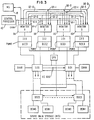
- FIG. 3 illustrates the manner in which the invention monitors a multiprocessor (MP) system. It includes a plurality of monitors 9 respectively connected to the central processors being monitored (PBM0PBM3). Monitors 9 are interconnected in a special way by lines Q to be able to detect which events in any PBM may have been caused by operation of another PBM and to identify the causative instruction in the other PBM.
- An MP having up to four PMBs i.e. CPO, CP1, CP2 and CP3 is disclosed and claimed in the European Patent Application 81 107928.4, publication number 0051 745.
- a single control processor (Ctl. P) 10 controls the operation of all monitors 9-0 through 9-3 of the MP system.
- Control processor 10 issues control commands on a single channel which is connected to each of the four monitors 9-0, 9-1, 9-2 and 9-3 which appear as I/O devices to control processor 10.
- the control processor issues sequential read commands to the four monitors so that simultaneously captured data is outputted to the channel as a related group containing the predetermined sequence of captured data from the four monitors, and the group is stored in the main storage (MS) 19 of processor 10, from which the data can be transferred to an I/O device, e.g. tape or disk if required.
- MS main storage
- each monitor 9 contains a monitor controller 11 which connects monitor 9 to a channel of the control processor 10, an event capture means (ECM) 12 which is connected to the PBM and captures monitored data in five byte units, a FIFO (first-in, first-out) buffer 15 which receives each five byte captured data unit immediately after it is captured, a FIFO overrun counter 15A which detects each time an event was not captured when it should have been captured, and a multirange comparator (MRC) 16 and its counters 17 which counts the number of times that captured events fall into respective predetermined address ranges.
- ECM event capture means
- MRC multirange comparator
- An OR circuit 18 connects the output data provided by the FIFO buffer 15, FIFO overrun counter 15A, or MRC counters 17 to the main storage (MS) 19 of the control processor 10 in response to an appropriate read command from processor 10 to monitor controller 15.
- the monitor controller 11 acts as an I/O control unit to decode each channel command sent to the monitor by control processor 10.
- channel commands are: (1) enable monitor, (2) set PSR (personalization register), clear and read FIFO buffer, read FIFO buffers, read counters, user defined condition (UDC), etc.
- the enable monitor command enables the addressed monitor to operate.
- the set PSR command loads a personalization register in the monitor with data for initializing a particular monitoring operation, i.e. which event will be captured, its sampling rate, other event(s) to be simultaneously monitored, etc.
- the clear and read FIFO buffer command first clears a first-in, first-out (FIFO) buffer 15 and sets the FIFO readin and readout points to FIFO location zero; and as FIFO buffer 15 receives captured data in 5 byte groups they are readout a byte at a time to the control processor main storage (MS) 19.
- the read port of the command is active for the entire measurement operation.
- the read FIFO buffer command reads out the next five byte units of captured data in the FIFO buffer 15 to MS 19 at the current FIFO readout pointer setting and increments the setting by one after the captured data unit is readout.
- the UDC command sets up the inputs to monitor 9 according to boolean conditions defined in the command to control the monitoring operation during the monitoring run. (The UDC command is not part of the subject invention).
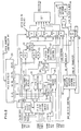
- FIG. 2 illustrates a block diagram of the circuit contents in ECM 12 shown in Figure 1.
- ECM 12 is initialized for a performance measurement of the PBM by a set PSR command loading the fields in a personalization register (PSR) 24, which is shown in detail in Figure 8.
- PSR personalization register
- the capturable event may occur asynchronously in relation to time.
- ECM 12 When in IA mode, ECM 12 relates the occurrence of the capturable event to the instruction causing the event by generating a trigger signal to capture the associated IA value when that event happens.
- ECM 12 Upon the occurrence of each Nth capturable event, ECM 12 captures the then current instruction address, a signal indicating the on or off state at capture time of an additional event specified by PSR bits FGH, and an additional byte including the status of PBM at the time of capture.
- the captured data in this embodiment comprises four bytes for the instruction address and additional event state, and a fifth byte containing PBM status data and an indication if the FIFO buffer is then in an overrun state. If the FIFO buffer is not in an overrun state, the captured five byte data units are immediately outputted to the FIFO buffer 15 from which the captured data unit is transferred to MS 19 under a read command from the control processor 10.
- control processor cannot take the data unit from buffer 15 before the next unit is captured, the captured units are collected in buffer 15 until called for by processor 10. If FIFO buffer 15 should become full, it generates an overrun signal which prevents buffer 15 from receiving any more captured data until at least one byte is readout, which allows a byte to be received from the capture register 41 in the readout byte location. While any overrun exists, each captured data unit instead increments the FIFO overrun counter 15A.
- monitor 9 is connected to busses 13 from PBM.
- the set of signals on bus 13A represent either an instruction address (IA) or a hook (HK) as indicated by a pulse on an IA signal line or a HK signal line in bus 13A.
- An event bus 13B and a state bus 13C each have respective lines which connect to various latches and circuits in PBM to sense the occurrence of respective events or states in PBM.
- the monitor will capture certain sets of signals on bus 13A because of the occurrence of a specified event on bus 13B during program execution by PBM.
- the monitors IA or HK operating mode is determined by the one or zero output of PSR bit position 1 to a mode select circuit 26. As shown in detail in Figure 9, a selected IA signal or hook signal generates a bus signal on line 26A. A sequence of signals on line 26A sets a pointer flip-flop 31 to alternate its on and off outputs. Registers RA 32 and RB 33 therefore alternately receive the content of IA/HK bus 13A from the PBM in a ping-pong manner under control of the alternating outputs of pointer flip-flop 31.
- Event bus 13B comprises lines which receive the event signals from PBM listed in the following table 1:
- an event capture switch (ECS) 27 receives inputs from bus 13B and also may receive capture signals Q1, Q2 and/or Q3 from other monitors if this monitor QO is connected in an MP.
- ECS 27 is a crosspoint type of switch which can select any of its input signals as its output signal.
- PSR bits 14-18 (designated ABCDE) are provided to ECS 27 to select one of the inputs as the capturable signal representing the capturable event.
- Table 2 lists the capturable events:
- Each occurrence of the selected capturable event causes a trigger signal at the output of ECS 27 which is provided to the input of a sample counter 28 and to a correlation control 29 shown in detail in Figure 7.
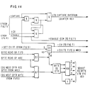
- the sampling counter 28 may be a 12-bit count-up counter. It controls the frequency of capture known as sampling rate N. Counter 28 is incremented by 1 each time ECS 27 outputs a tigger signal. The trigger signal following the sampling counter overflow will signal the correlation control 29 to capture the current instruction address and load it into a capture register 41.
- the number of trigger signals between captures is specified by N, which may be any value from 1 to 4095.
- Each Nth trigger signal outputted by ECS 27 causes the sampling counter 28 to overflow and generate a capture signal in circuit 29A which is sent to circuits 37A and 37B in Figure 9 which outgate the register RA or RB containing the address of the current instruction causing the selected event.
- the instruction address is transferred into bit positions 0-30 in capture register 41 in Figure 10.
- any of a special set of events if selected for capture, will bypass the operation of sampling counter 28 and cause a capture of the IA in register 41 on every occurrence.
- These special events are the first six events listed in Table 2. The remaining events in Table 2 are controlled by the operation of sampling counter 28.
- the PSR bits A-E are received, and the codes for the bypassed special events are sensed in circuits 29B, etc., to control the bypassing of the trigger signals via circuit 29C to activate capture flip-flop 29D which generates a capture signal that is passed through circuit 29A to control the outgating of the current IA from RA or RB to capture register 41 in Figure 10.
- bit position 31 is not needed for containing the IA and is used to represent the state of the additional event selected by ESS 45, because in an IBM S/370 architecture, bit 31 is not used to address instructions in the main storage since the shortest instruction is one-half word long and is addressed on one-half word boundaries (i.e. bit 30). Although bit position 31 on IA bus 30 is never used in IA mode, bit 31 may be used in hook mode. Therefore, in IA mode, position 31 in capture register 41 is used to record the state of the event selected by ESS 45 at each capture time, and bit 31 may represent the state of any event selected by PSR bits FGH in the following Table 5:
- ESS 45 also is a crosspoint type of switch.
- the combinatorial state of bits FGH selects one of the PBM inputs to ESS 45 as its output to bit position 31 in register 41. Therefore, bit position 31 in register 41 may be either one or zero with a captured IA.
- a capture valid (CV) flip/flop 43 is set.
- the CV signals the FIFO buffer 15 that byte 0 is being outputted from capture register 41 to buffer 15.
- a return signal from FIFO is provided to an outgate control 42 to cause the next captured byte to be outgated from register 41. This sequence is repeated until all five bytes are transferred to the FIFO buffer.
- CV flip flop 43 is reset. Register 41 is now ready to capture another instruction address.
- sampling counter 28 While register 41 is busy outgating its contents, the sampling counter 28 continues counting trigger pulses received from ECS 27. If sampling counter 28 overflows while the capture register 41 is outgating, sampling counter 28 is again loaded from the PSR with its count value; but instead of an IA capture occurring on such overflow, a capture overrun signal is raised to increment a capture overrun counter 46.
- the maximum rate at which the captures can occur is dependent on the execution rate of the PBM; the faster its execution rate, the sooner the next capture can occur.
Landscapes
- Engineering & Computer Science (AREA)
- General Engineering & Computer Science (AREA)
- Theoretical Computer Science (AREA)
- Computer Hardware Design (AREA)
- Quality & Reliability (AREA)
- Physics & Mathematics (AREA)
- General Physics & Mathematics (AREA)
- Debugging And Monitoring (AREA)
Claims (15)
Applications Claiming Priority (2)
| Application Number | Priority Date | Filing Date | Title |
|---|---|---|---|
| US06/273,530 US4435759A (en) | 1981-06-15 | 1981-06-15 | Hardware monitor for obtaining processor software/hardware interrelationships |
| US273530 | 1981-06-15 |
Publications (3)
| Publication Number | Publication Date |
|---|---|
| EP0067324A2 EP0067324A2 (fr) | 1982-12-22 |
| EP0067324A3 EP0067324A3 (en) | 1985-03-27 |
| EP0067324B1 true EP0067324B1 (fr) | 1988-11-23 |
Family
ID=23044320
Family Applications (1)
| Application Number | Title | Priority Date | Filing Date |
|---|---|---|---|
| EP82104510A Expired EP0067324B1 (fr) | 1981-06-15 | 1982-05-24 | Système de surveillance corrélateur matériel-logiciel |
Country Status (4)
| Country | Link |
|---|---|
| US (1) | US4435759A (fr) |
| EP (1) | EP0067324B1 (fr) |
| JP (1) | JPS57211655A (fr) |
| DE (1) | DE3279236D1 (fr) |
Families Citing this family (59)
| Publication number | Priority date | Publication date | Assignee | Title |
|---|---|---|---|---|
| US4485440A (en) * | 1981-09-24 | 1984-11-27 | At&T Bell Laboratories | Central processor utilization monitor |
| DE3218277A1 (de) * | 1982-05-14 | 1983-11-17 | Siemens AG, 1000 Berlin und 8000 München | Schaltungsanordnung fuer fernmeldevermittlungsanlagen, insbesondere fernsprechvermittlungsanlagen, mit einer abwicklung der vermittlungsschaltvorgaenge dienenden multirechnersystemen |
| US4598364A (en) * | 1983-06-29 | 1986-07-01 | International Business Machines Corporation | Efficient trace method adaptable to multiprocessors |
| US4590550A (en) * | 1983-06-29 | 1986-05-20 | International Business Machines Corporation | Internally distributed monitoring system |
| US4638427A (en) * | 1984-04-16 | 1987-01-20 | International Business Machines Corporation | Performance evaluation for an asymmetric multiprocessor system |
| US4660198A (en) * | 1985-04-15 | 1987-04-21 | Control Data Corporation | Data capture logic for VLSI chips |
| FR2591364B1 (fr) * | 1985-12-05 | 1990-11-02 | Mary Joel | Dispositif d'evaluation, par mesure, des performances d'un systeme informatique. |
| US4821178A (en) * | 1986-08-15 | 1989-04-11 | International Business Machines Corporation | Internal performance monitoring by event sampling |
| US5263153A (en) * | 1987-01-22 | 1993-11-16 | National Semiconductor Corporation | Monitoring control flow in a microprocessor |
| ATE109910T1 (de) * | 1988-01-20 | 1994-08-15 | Advanced Micro Devices Inc | Organisation eines integrierten cachespeichers zur flexiblen anwendung zur unterstützung von multiprozessor-operationen. |
| US5113518A (en) * | 1988-06-03 | 1992-05-12 | Durst Jr Robert T | Method and system for preventing unauthorized use of software |
| US5287511A (en) * | 1988-07-11 | 1994-02-15 | Star Semiconductor Corporation | Architectures and methods for dividing processing tasks into tasks for a programmable real time signal processor and tasks for a decision making microprocessor interfacing therewith |
| US5263143A (en) * | 1988-07-11 | 1993-11-16 | Star Semiconductor Corporation | Real time probe device for internals of signal processor |
| JPH02199548A (ja) * | 1988-11-09 | 1990-08-07 | Asea Brown Boveri Ag | 電算機系で作成されるオブジエクト・プログラムの時間経過を観察する方法とこの方法を実行する観測器具 |
| US5465258A (en) * | 1989-11-13 | 1995-11-07 | Integrity Systems, Inc. | Binary image performance evaluation tool |
| US5551050A (en) * | 1989-12-20 | 1996-08-27 | Texas Instruments Incorporated | System and method using synchronized processors to perform real time internal monitoring of a data processing device |
| US5121501A (en) * | 1989-12-27 | 1992-06-09 | International Business Machines Corporation | First processor inserting hooks into software and sending unique identifications to output bus and second processor associating data frames and time with these unique identifications |
| JPH05509425A (ja) * | 1990-05-18 | 1993-12-22 | スター・セミコンダクター・コーポレーション | プログラム可能信号プロセッサ・アーキテクチャ |
| AU8726791A (en) * | 1990-09-17 | 1992-04-15 | Star Semiconductor Corporation | Event signalling system and method for processor system having central memory unit |
| US5361355A (en) * | 1991-02-08 | 1994-11-01 | Fujitsu Limited | Software asset systemizer |
| US5426741A (en) * | 1991-02-20 | 1995-06-20 | Digital Equipment Corporation | Bus event monitor |
| JPH0816877B2 (ja) * | 1991-06-10 | 1996-02-21 | インターナショナル・ビジネス・マシーンズ・コーポレイション | データ処理システム用資源データの実時間捕獲及び減縮方法及びシステム |
| US5440722A (en) * | 1991-07-22 | 1995-08-08 | Banyan Systems, Inc. | System bus monitor for compiling data regarding use of a system bus |
| US5418930A (en) * | 1991-09-05 | 1995-05-23 | International Business Machines Corporation | Circuit for interfacing asynchronous to synchronous communications |
| US5450349A (en) * | 1992-10-27 | 1995-09-12 | Digital Equipment Corporation | Computer system performance evaluation system and method |
| US5452457A (en) * | 1993-01-29 | 1995-09-19 | International Business Machines Corporation | Program construct and methods/systems for optimizing assembled code for execution |
| AU1435795A (en) * | 1993-12-15 | 1995-07-03 | Supercomm, Inc. | Database versioning with output only of data changed from the previous version |
| US5537541A (en) * | 1994-08-16 | 1996-07-16 | Digital Equipment Corporation | System independent interface for performance counters |
| JP2908739B2 (ja) * | 1994-12-16 | 1999-06-21 | インターナショナル・ビジネス・マシーンズ・コーポレイション | 多重プロセッサ・システムにおけるcpuのモニタリング・システム及び方法 |
| US6021457A (en) * | 1995-09-28 | 2000-02-01 | Intel Corporation | Method and an apparatus for minimizing perturbation while monitoring parallel applications |
| US5748855A (en) * | 1995-10-02 | 1998-05-05 | Iinternational Business Machines Corporation | Method and system for performance monitoring of misaligned memory accesses in a processing system |
| US5752062A (en) * | 1995-10-02 | 1998-05-12 | International Business Machines Corporation | Method and system for performance monitoring through monitoring an order of processor events during execution in a processing system |
| US5949971A (en) * | 1995-10-02 | 1999-09-07 | International Business Machines Corporation | Method and system for performance monitoring through identification of frequency and length of time of execution of serialization instructions in a processing system |
| US5751945A (en) * | 1995-10-02 | 1998-05-12 | International Business Machines Corporation | Method and system for performance monitoring stalls to identify pipeline bottlenecks and stalls in a processing system |
| US5729726A (en) * | 1995-10-02 | 1998-03-17 | International Business Machines Corporation | Method and system for performance monitoring efficiency of branch unit operation in a processing system |
| US5691920A (en) * | 1995-10-02 | 1997-11-25 | International Business Machines Corporation | Method and system for performance monitoring of dispatch unit efficiency in a processing system |
| US5797019A (en) * | 1995-10-02 | 1998-08-18 | International Business Machines Corporation | Method and system for performance monitoring time lengths of disabled interrupts in a processing system |
| US5968188A (en) * | 1998-03-10 | 1999-10-19 | Grammar Engine | System for providing real-time code coverage |
| US6134676A (en) * | 1998-04-30 | 2000-10-17 | International Business Machines Corporation | Programmable hardware event monitoring method |
| US6370659B1 (en) | 1999-04-22 | 2002-04-09 | Harris Corporation | Method for automatically isolating hardware module faults |
| US6460107B1 (en) | 1999-04-29 | 2002-10-01 | Intel Corporation | Integrated real-time performance monitoring facility |
| US6611926B1 (en) * | 1999-11-29 | 2003-08-26 | Hewlett-Packard Development Company, L.P. | Mechanisms to sample shared-dirty-line addresses |
| US6748558B1 (en) * | 2000-05-10 | 2004-06-08 | Motorola, Inc. | Performance monitor system and method suitable for use in an integrated circuit |
| US6542844B1 (en) * | 2000-08-02 | 2003-04-01 | International Business Machines Corporation | Method and apparatus for tracing hardware states using dynamically reconfigurable test circuits |
| US20020073406A1 (en) * | 2000-12-12 | 2002-06-13 | Darryl Gove | Using performance counter profiling to drive compiler optimization |
| CN1669271A (zh) * | 2002-07-18 | 2005-09-14 | Vega格里沙贝两合公司 | 具有集成总线监控功能的总线站 |
| GB2393272A (en) * | 2002-09-19 | 2004-03-24 | Advanced Risc Mach Ltd | Controlling performance counters within a data processing system |
| US7451459B2 (en) * | 2003-05-05 | 2008-11-11 | Microsoft Corporation | Systems, methods, and apparatus for indicating processor hierarchical topology |
| US7165145B2 (en) * | 2003-07-02 | 2007-01-16 | Falconstor Software, Inc. | System and method to protect data stored in a storage system |
| US7334114B2 (en) * | 2005-05-16 | 2008-02-19 | Texas Instruments Incorporated | Real-time monitoring, alignment, and translation of CPU stalls or events |
| US8516226B1 (en) * | 2006-01-23 | 2013-08-20 | Hewlett-Packard Development Company, L.P. | Executing a prefetching policy responsive to entry into an execution phase of an application |
| US7873534B2 (en) * | 2006-02-14 | 2011-01-18 | Microsoft Corporation | Collecting CRM data for feedback |
| US8656411B2 (en) | 2008-03-05 | 2014-02-18 | Intel Corporation | Technique for monitoring activity within an integrated circuit |
| US20100008464A1 (en) * | 2008-07-11 | 2010-01-14 | Infineon Technologies Ag | System profiling |
| US9032375B2 (en) * | 2011-04-27 | 2015-05-12 | International Business Machines Corporation | Performance bottleneck identification tool |
| CN105706063A (zh) * | 2013-12-12 | 2016-06-22 | 英特尔公司 | 用于检测竞争条件的技术 |
| US9454424B2 (en) | 2014-08-27 | 2016-09-27 | Freescale Semiconductor, Inc. | Methods and apparatus for detecting software inteference |
| DE102015217074A1 (de) | 2015-09-07 | 2017-03-09 | Siemens Aktiengesellschaft | Verfahren und Vorrichtung zur dynamischen Korrektheitsanalyse von Software |
| US10732852B1 (en) * | 2017-10-19 | 2020-08-04 | EMC IP Holding Company LLC | Telemetry service |
Family Cites Families (4)
| Publication number | Priority date | Publication date | Assignee | Title |
|---|---|---|---|---|
| US3818458A (en) | 1972-11-08 | 1974-06-18 | Comress | Method and apparatus for monitoring a general purpose digital computer |
| US4241416A (en) * | 1977-07-01 | 1980-12-23 | Systron-Donner Corporation | Monitoring apparatus for processor controlled equipment |
| US4166290A (en) * | 1978-05-10 | 1979-08-28 | Tesdata Systems Corporation | Computer monitoring system |
| US4250562A (en) * | 1979-05-22 | 1981-02-10 | Hewlett-Packard Company | Digital signal state analyzer and display |
-
1981
- 1981-06-15 US US06/273,530 patent/US4435759A/en not_active Expired - Fee Related
-
1982
- 1982-05-24 EP EP82104510A patent/EP0067324B1/fr not_active Expired
- 1982-05-24 DE DE8282104510T patent/DE3279236D1/de not_active Expired
- 1982-06-15 JP JP57101485A patent/JPS57211655A/ja active Pending
Also Published As
| Publication number | Publication date |
|---|---|
| JPS57211655A (en) | 1982-12-25 |
| EP0067324A2 (fr) | 1982-12-22 |
| DE3279236D1 (en) | 1988-12-29 |
| US4435759A (en) | 1984-03-06 |
| EP0067324A3 (en) | 1985-03-27 |
Similar Documents
| Publication | Publication Date | Title |
|---|---|---|
| US4435759A (en) | Hardware monitor for obtaining processor software/hardware interrelationships | |
| US4821178A (en) | Internal performance monitoring by event sampling | |
| US8978017B2 (en) | Profiling operating context | |
| US5151981A (en) | Instruction sampling instrumentation | |
| EP0130469B1 (fr) | Système moniteur distribué intérieurement | |
| US3540003A (en) | Computer monitoring system | |
| US8141053B2 (en) | Call stack sampling using a virtual machine | |
| US6539500B1 (en) | System and method for tracing | |
| US5608866A (en) | System for measuring and analyzing operation of information processor | |
| KR100280732B1 (ko) | 데이터처리시스템의성능모니터링방법및장치 | |
| US5835702A (en) | Performance monitor | |
| US5193179A (en) | Activity monitor system non-obtrusive statistical monitoring of operations on a shared bus of a multiprocessor system | |
| US5265240A (en) | Channel measurement method and means | |
| US3825901A (en) | Integrated diagnostic tool | |
| US4503495A (en) | Data processing system common bus utilization detection logic | |
| US4367525A (en) | CPU Channel monitoring system | |
| US5920689A (en) | System and method for low overhead, high precision performance measurements using state transitions | |
| US4458309A (en) | Apparatus for loading programmable hit matrices used in a hardware monitoring interface unit | |
| EP0076921B1 (fr) | Méthode et système pour la mesure de temps de canaux de traitement de données | |
| US3723975A (en) | Overdue event detector | |
| CA1123106A (fr) | Systeme de controle informatise | |
| US4949252A (en) | Computer channel analyzer with monitoring and selective display of predetermining events and related data | |
| US20060005083A1 (en) | Performance count tracing | |
| JPH05197594A (ja) | データ処理システム用資源データの実時間捕獲及び減縮方法及びシステム | |
| US7225105B2 (en) | Extending width of performance monitor counters |
Legal Events
| Date | Code | Title | Description |
|---|---|---|---|
| PUAI | Public reference made under article 153(3) epc to a published international application that has entered the european phase |
Free format text: ORIGINAL CODE: 0009012 |
|
| AK | Designated contracting states |
Designated state(s): DE FR GB IT |
|
| 17P | Request for examination filed |
Effective date: 19830420 |
|
| PUAL | Search report despatched |
Free format text: ORIGINAL CODE: 0009013 |
|
| AK | Designated contracting states |
Designated state(s): DE FR GB IT |
|
| 17Q | First examination report despatched |
Effective date: 19860506 |
|
| GRAA | (expected) grant |
Free format text: ORIGINAL CODE: 0009210 |
|
| AK | Designated contracting states |
Kind code of ref document: B1 Designated state(s): DE FR GB IT |
|
| PG25 | Lapsed in a contracting state [announced via postgrant information from national office to epo] |
Ref country code: IT Free format text: LAPSE BECAUSE OF FAILURE TO SUBMIT A TRANSLATION OF THE DESCRIPTION OR TO PAY THE FEE WITHIN THE PRESCRIBED TIME-LIMIT;WARNING: LAPSES OF ITALIAN PATENTS WITH EFFECTIVE DATE BEFORE 2007 MAY HAVE OCCURRED AT ANY TIME BEFORE 2007. THE CORRECT EFFECTIVE DATE MAY BE DIFFERENT FROM THE ONE RECORDED. Effective date: 19881123 |
|
| REF | Corresponds to: |
Ref document number: 3279236 Country of ref document: DE Date of ref document: 19881229 |
|
| ET | Fr: translation filed | ||
| PGFP | Annual fee paid to national office [announced via postgrant information from national office to epo] |
Ref country code: FR Payment date: 19890426 Year of fee payment: 8 |
|
| PGFP | Annual fee paid to national office [announced via postgrant information from national office to epo] |
Ref country code: GB Payment date: 19890430 Year of fee payment: 8 |
|
| PLBE | No opposition filed within time limit |
Free format text: ORIGINAL CODE: 0009261 |
|
| STAA | Information on the status of an ep patent application or granted ep patent |
Free format text: STATUS: NO OPPOSITION FILED WITHIN TIME LIMIT |
|
| 26N | No opposition filed | ||
| PG25 | Lapsed in a contracting state [announced via postgrant information from national office to epo] |
Ref country code: DE Effective date: 19900201 |
|
| PG25 | Lapsed in a contracting state [announced via postgrant information from national office to epo] |
Ref country code: GB Effective date: 19900524 |
|
| GBPC | Gb: european patent ceased through non-payment of renewal fee | ||
| PG25 | Lapsed in a contracting state [announced via postgrant information from national office to epo] |
Ref country code: FR Effective date: 19910131 |
|
| REG | Reference to a national code |
Ref country code: FR Ref legal event code: ST |