EP0067378B1 - Erzwungen-adaptiver Entzerrer - Google Patents
Erzwungen-adaptiver Entzerrer Download PDFInfo
- Publication number
- EP0067378B1 EP0067378B1 EP82104896A EP82104896A EP0067378B1 EP 0067378 B1 EP0067378 B1 EP 0067378B1 EP 82104896 A EP82104896 A EP 82104896A EP 82104896 A EP82104896 A EP 82104896A EP 0067378 B1 EP0067378 B1 EP 0067378B1
- Authority
- EP
- European Patent Office
- Prior art keywords
- constrained
- phase
- adaptive equalizer
- trailing
- signal
- Prior art date
- Legal status (The legal status is an assumption and is not a legal conclusion. Google has not performed a legal analysis and makes no representation as to the accuracy of the status listed.)
- Expired
Links
- 230000003044 adaptive effect Effects 0.000 title claims description 115
- 238000004891 communication Methods 0.000 claims description 25
- 238000002592 echocardiography Methods 0.000 claims description 25
- 230000005540 biological transmission Effects 0.000 claims description 19
- 230000015654 memory Effects 0.000 claims description 15
- 230000003321 amplification Effects 0.000 description 10
- 238000003199 nucleic acid amplification method Methods 0.000 description 10
- 238000012937 correction Methods 0.000 description 7
- 238000011084 recovery Methods 0.000 description 7
- 238000010586 diagram Methods 0.000 description 6
- 230000001419 dependent effect Effects 0.000 description 5
- 238000005070 sampling Methods 0.000 description 5
- 238000007493 shaping process Methods 0.000 description 5
- 238000001228 spectrum Methods 0.000 description 5
- 238000011161 development Methods 0.000 description 3
- 238000000034 method Methods 0.000 description 3
- 238000012545 processing Methods 0.000 description 3
- 238000013459 approach Methods 0.000 description 2
- 230000000694 effects Effects 0.000 description 2
- 239000002243 precursor Substances 0.000 description 2
- 230000006399 behavior Effects 0.000 description 1
- 230000003111 delayed effect Effects 0.000 description 1
- 230000006870 function Effects 0.000 description 1
- 230000005055 memory storage Effects 0.000 description 1
- 238000012986 modification Methods 0.000 description 1
- 230000004048 modification Effects 0.000 description 1
- 230000001360 synchronised effect Effects 0.000 description 1
- 238000012549 training Methods 0.000 description 1
Images


Classifications
-
- H—ELECTRICITY
- H04—ELECTRIC COMMUNICATION TECHNIQUE
- H04L—TRANSMISSION OF DIGITAL INFORMATION, e.g. TELEGRAPHIC COMMUNICATION
- H04L27/00—Modulated-carrier systems
- H04L27/01—Equalisers
-
- H—ELECTRICITY
- H04—ELECTRIC COMMUNICATION TECHNIQUE
- H04L—TRANSMISSION OF DIGITAL INFORMATION, e.g. TELEGRAPHIC COMMUNICATION
- H04L25/00—Baseband systems
- H04L25/02—Details ; arrangements for supplying electrical power along data transmission lines
- H04L25/03—Shaping networks in transmitter or receiver, e.g. adaptive shaping networks
- H04L25/03006—Arrangements for removing intersymbol interference
- H04L25/03012—Arrangements for removing intersymbol interference operating in the time domain
- H04L25/03019—Arrangements for removing intersymbol interference operating in the time domain adaptive, i.e. capable of adjustment during data reception
- H04L25/03038—Arrangements for removing intersymbol interference operating in the time domain adaptive, i.e. capable of adjustment during data reception with a non-recursive structure
-
- H—ELECTRICITY
- H04—ELECTRIC COMMUNICATION TECHNIQUE
- H04L—TRANSMISSION OF DIGITAL INFORMATION, e.g. TELEGRAPHIC COMMUNICATION
- H04L25/00—Baseband systems
- H04L25/02—Details ; arrangements for supplying electrical power along data transmission lines
- H04L25/03—Shaping networks in transmitter or receiver, e.g. adaptive shaping networks
- H04L25/03006—Arrangements for removing intersymbol interference
- H04L25/03012—Arrangements for removing intersymbol interference operating in the time domain
- H04L25/03019—Arrangements for removing intersymbol interference operating in the time domain adaptive, i.e. capable of adjustment during data reception
- H04L25/03057—Arrangements for removing intersymbol interference operating in the time domain adaptive, i.e. capable of adjustment during data reception with a recursive structure
Definitions
- the present invention relates generally to adaptive equalizers for baseband and carrier modulation systems such as single sideband and quadrature amplitude modulation communication systems, and more particularly to a constrained adaptive equalizer for use in eliminating amplitude and delay distortions in a digital signal.
- the present invention relates to an equalizer for digital communication systems in accordance with the prior art portion of claim 1.
- the transversal equalizer of this prior art device includes a linear filter to which a pure phase equalizer is added (page 255, line 6 from the bottom).
- the transversal equalizer of the prior art device is not only an all-pass network, since only one of two filters connected in series connection and forming together the transversal equalizer is a pure phase equalizer (page 256, first four lines).
- the second linear filter forming one part of the transversal equalizer of the prior art device is a so-called minimum delay network (page 257, second paragraph).
- a decision means which is a digital detector element is connected to the output of the transversal equalizer.
- the output of the detector forms the output of the prior art equalizer, which in turn is fed back to the connection point between the transversal equalizer and the detector itself by means of a feedback equalizer.
- the feedback equalizer is a linear transversal filter. This prior art system has a higher noise level when compared to that which will be hereinafter described.
- ISI intersymbol interference
- Intersymbol interference and noise result in errors in determining the value of the transmitted signal at the receiver.
- the effect of intersymbol interference is to increase the likelihood that any noise in the system will lead to such error.
- Adaptive equalizers have been used to reduce intersymbol interference. All methods and devices for adaptively equalizing the digital signal proposed thus far produce some noise amplification. It is noted that these problems of noise and distortion exist in both baseband and passband communication systems. Further, it is noted that adaptive equalization has been used to suppress distortion in both types of systems.
- transversal equalizers In the development of equalization techniques, initially the structures proposed for both baseband and passband were pure transversal equalizers. These equalizers adequately suppress ISI but may excessively amplify system noise. These transversal equalizers have leading and lagging taps (multiplying coefficients) for operation on precursors (leading echoes) and postcursors (trailing echoes) of the received signal, respectively.
- the systems utilizing one-sided transversal equalizers recognize the presence of nulls in the sampled spectrum.
- the decision feedback equalizer for the postcursor correction the effect of noise amplification from equalization of all of the nulls in the sample spectrum is reduced.
- GB-A-2 003 690 discloses a digital processing system having a device for generating sampled values of an input signal to be processed.
- the sampled values of the input signal are stored in a member.
- the stored values are fed to a multiplier which in turn multiplies the stored values with digital coefficients forming the filter characteristic of the digital filter. Thereinafter, these values are stored in an output buffer.
- the present invention is based on the object of providing a constrained adaptive equalizer for digital communication systems having an improved noise behaviour for further reducing the intersymbol interference.
- the adaptive equalizer of the present invention provides a means for equalization that contributes significantly less noise than the prior systems while continuing to minimize the intersymbol interference.
- This adaptive equalizer corrects for leading and trailing echoes by using a transversal equalizer in combination with a decision feedback equalizer, wherein the transversal equalizer approximates a phase equalizer by constraining its multiplying coefficients, i.e., taps, in accordance with the symmetry of the differential delay characteristic of the transmission medium around a signal carrier frequency.
- the equalizer of the present invention may be utilized either in a baseband type system or a carrier type system based on quadrature amplitude modulation (QAM).
- QAM quadrature amplitude modulation
- serial binary data is transformed to a complex data signal for transmission to a remote location via a transmission medium.
- a receiver is provided at the remote location for receiving the transmitted signal.
- One of the components of this receiver is the constrained adaptive equalizer of the present invention.
- the present constrained adaptive equalizer is provided with a constrained transversal adaptive equalizer in combination with a decision feedback equalizer and means for determining the value of the transmitted signal.
- the constrained transversal adaptive equalizer is provided with leading and trailing multiplying coefficients for correcting the leading echoes in a received digital signal, thereby generating a phase equalized signal. These trailing coefficients are constrained so that the adaptive transversal equalizer approximates, as closely as possible, a phase equalizer.
- the equalizer taps and the sampled data going into the equalizer are one dimensional (real numbers).
- both the sampled data and the taps are two dimensional (complex numbers). The real and imaginary parts of these numbers are, respectively, the in-phase and quadrature components.
- the "carrier frequency” is zero. Therefore, the phase characteristic of the received signal is always antisymmetric; and the required constraint on the taps is that they be antisymmetric as well.
- the trailing multiplying coefficients of the transversal equalizer are negatively symmetric in the in-phase component and positively symmetric in the quadrature component of the multiplying coefficients to the corresponding in-phase and quadrature components of the leading multiplying coefficients.
- the trailing multiplying coefficients of the transversal equalizer are positively symmetric in both the in-phase and quadrature components of the trailing multiplying coefficients to the in-phase and quadrature components of the leading multiplying coefficients.
- the constrained adaptive equalizer further includes a decision feedback equalizer having trailing multiplying coefficients for simulating trailing echoes in the phase equalized signal.
- a decision feedback equalizer having trailing multiplying coefficients for simulating trailing echoes in the phase equalized signal.
- a decision means for determining the value of the received data signal is provided utilizing the phase equalized signal from the transversal adaptive equalizer and an equalized signal representative of the difference between the phase equalized signal and the simulated echoes, to decide on the value of the received signal when compared to a predetermined threshold value.
- the decision means further includes a means for generating an error signal representing the amplitude difference between the equalized data signal and the decided value signal.
- the decision means also includes a means for correcting the phase difference between the equalized signal and the decided value output data signal.
- the constrained adaptive equalizer also includes means for adaptively updating the leading multiplying coefficients of the constrained transversal adaptive equalizer and the trailing multiplying coefficients of the decision feedback equalizer.
- This adaptive updating for the leading multiplying coefficients of the constrained transversal adaptive equalizer is accomplished by cross-correlation of the present error signal generated by the decision means with the past and present received data signals associated with each of said leading multiplying coefficients.
- Adaptive updating of the trailing multiplying coefficients of the decision feedback equalizer is accomplished by cross-correlating the error signal with the decided output data signal.
- a means is also provided for controlled updating of the trailing multiplying coefficients of the constrained transversal adaptive equalizer. The controlled updating is dependent upon the symmetry of the differential delay characteristics of the transmission medium around a space selected carrier frequency.
- the means for correcting for phase difference between the equalized signal and the decided value signal in the constrained adaptive equalizer of the previously described embodiment includes a means for determining the angular error between the equalized signal and the output data signal. This angular error is transmitted to a phase locked loop for generating an angle of rotation which is then transmitted to a means for rotating the phase equalized signal.
- the constrained adaptive transversal equalizer in a first embodiment comprises a delay line shift register having a plurality of stages each of which can accommodate a digital word having a known length.
- the transversal equalizer also includes a series of storage elements containing the leading and trailing multiplying coefficients. Each of these storage elements is electrically connected to a different individual stage of the shift register.
- a series of multipliers are provided, electrically associated with each of the storage elements and their respective shift register stages, for multiplying the contents of each shift register stage by the corresponding multiplying constant.
- a summing element is provided to store the accumulated product of each of the stages of the shift register and their corresponding multiplying coefficients.
- the decision feedback equalizer in the first embodiment comprises a delay-line shift register, similar to the delay-line shift register in the constrained adaptive transversal equalizer, having a plurality of stages with each stage accommodating a digital word having a known length.
- the decision feedback equalizer also includes a plurality of storage elements associated with a different individual stage of the shift register for storing trailing multiplying coefficients.
- a series of multipliers are electrically associated with each of the stages of the delay-line shift register of the decision feedback equalizer and their corresponding storage element for multiplying the constants stored in the storage elements by the values stored in each of the respective stages in the shift register.
- a summing element is provided to accumulate the products of these multiplications.
- a microprocessor based digital signal processor is utilized in combination with digital memories.
- the digital memories used in this combination include a random access memory and a read only memory.
- the random access memory implements the functional elements of the adaptive equalizer while the read only memory contains an instruction set whose execution approximates phase equalization of an incoming digital signal.
- the random access digital memory has a plurality of storage locations with a predefined number of those locations implementing a first digital delay line. A corresponding number of these locations store leading and trailing multiplying coefficients for correction of delay distortion. A predefined number of locations implement a second digital delay line with a corresponding number of locations storing trailing coefficients for correction for amplitude distortion. It is noted that both the in-phase and quadrature components of these coefficients are being stored in the random access memory locations for carrier-type systems whereas only a single set of coefficients is required for baseband type systems.
- the read only digital memory has a plurality of storage locations. Included in these locations is a set of digital instructions for approximating phase equalizing and amplitude equalizing the digital signal received by the digital processing unit.
- the digital instructions are further detailed to determine the value of the incoming transmitted digital signal, computing the difference between the combination of the phase and amplitude equalized signals, updating the leading transversal multiplying coefficients for delay distortion and the trailing decision feedback multiplying coefficients for amplitude distortion, and controlled updating of the trailing coefficients for delay distortion.
- the controlled updating of the trailing transversal multiplying coefficients for correction of delay distortion is dependent upon the transmission medium's differential delay characteristic and whether the system is of the baseband-type or carrier-type.
- the trailing multiplying coefficients for delay distortion are negatively symmetric on the in-phase component and positively symmetric on the quadrature phase component to the corresponding in-phase and quadrature phase components of the leading multiplying coefficients.
- the trailing multiplying coefficients for delay distortion are positively symmetric on both the in-phase and quadrature components with respect to the in-phase and quadrature components of the leading multiplying coefficients.
- the constrained adaptive equalizer of the present invention is also a component part of a modem which uses either a baseband-type modulation scheme (including single-sideband modulation) or a carrier-type system which uses a quadrature amplitude modulation scheme.
- a transmitter is provided for sending digital signals representative of serial binary data.
- the transmitter utilizes a combination of phase and amplitude modulation of the carrier signal.
- Interface circuitry is also provided to the transmission medium for transmitting and receiving data signals.
- the modem includes a receiver for receiving a similarly modulated data signal.
- the receiver includes the constrained adaptive equalizer of the present invention for correcting amplitude and delay distortion in the data signal while minimizing noise amplification.
- the transmitter includes an encoder for encoding the data and representing it as an analog data signal, and a filter for shaping the analog data signal.
- the transmitter includes an encoder for encoding the data and separating the data into two discrete analog signals thereby transmitting a complex signal; filters for shaping each of the complex data signals; and modulators for modulating each of the data signals with two quadrature carrier signals.
- the receiver in both baseband and carrier type systems further includes a bandpass filter for limiting noise and providing shaping of the received signal; and an automatic gain control . amplifier for providing constant signal levels to the receiver elements.
- the receiver includes a phase splitting network for separating the digital signal into in-phase and quadrature component data signals; a baud rate sampler for sampling the in-phase and quadrature data signals at time epochs determined by the received data signal; and a demodulator for demodulating the carrier signal from the in-phase and quadrature data signal.
- a carrier recovery network is also provided in the receiver for synchronizing the received data signal with the demodulating signal.
- a heterodyner is provided for accepting data transmitted over both the highband and lowband channels.
- a receiver for a single sideband system includes similar components to a QAM receiver but does not include a phase splitter. Similarly, in a baseband system the receiver would resemble a single sideband receiver without the demodulator.
- the adaptive equalizer of the present invention is a further development of the use of the combination of transversal and decision feedback equalization.
- the present development involves a constrained adaptive equalizer with constraints on the taps of the transversal section of the equalizer, which has both leading and lagging taps. These constraints force the transversal equalizer to correct only the leading echoes of a received digital signal in a communication system and treat them as if they resulted only from phase distortion. These constraints transform the transversal equalizer into an approximating phase equalizer and therefore minimize any additional noise amplification to the received signal.
- the decision feedback equalizer in the present invention continues to cancel the postcursors or trailing echoes without the addition of any noise.
- the constrained adaptive equalizer of the present invention utilizes the combination of transversal phase equalization with decision feedback equalization.
- This combination can be used for either passband or baseband equalization and for either complex signals, such as QAM signals, or real signals, such as baseband or single sideband signals.
- complex signals such as QAM signals
- real signals such as baseband or single sideband signals.
- the appropriate constraints on the transversal equalizer, which has in-phase and quadrature- taps is dependent upon the expected symmetry of the differential delay characteristic of the transmission medium around a carrier frequency.
- a full channel telephone line i.e. full band or half duplex systems, where the transmission medium has a differential delay characteristic which is substantially even around the carrier frequency, there is negative symmetry on the in-phase taps and positive symmetry on the quadrature taps.
- a half channel telephone line i.e. half band or full duplex
- FIG. 1 a schematic illustration of an example of a differential delay characteristic of a typical telephone line is illustrated.
- the full band channel of a typical telephone line will normally encompass the frequencies of 600 to 3,000 Hz.
- the delay characteristic representation 1 in Figure 1 in the full band channel is approximately parabolic and centered at a carrier frequency of 1,800 Hz.
- the delay is approximately linear around the carrier frequencies for example 1,200 Hz and 2,400 Hz.
- An application of this observation lies in the combination transversal and decision feedback equalizer of the present invention: By treating all the leading echoes in a received signal as if they arose only from delay distortion the amount of noise amplification produced by these taps is minimized. Therefore, the constraints placed upon these taps is dependent upon the delay distortion characteristic of the transmission medium around the carrier frequency.
- the transversal equalizer In a complex (passband) system the transversal equalizer has in-phase and quadrature multiplying coefficients C to achieve equalization.
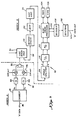
- the constrained adaptive equalizer 10 receives a complex data signal 12 having in-phase and quadrature components.
- the complex data signal 12 is received by a transversal equalizer 13 comprising an adaptive segment 14 and a constrained segment 16.
- the transversal equalizer 13 corrects the in-phase and quadrature components of the signal 12 for leading echoes by approximating phase equalization.
- the adaptive and constrained transversal equalization treats only the delay distortion characteristic of the in-phase and quadrature components of the complex data signal 12 thus delivering a phase equalized signal 18a.
- the constrained adaptive equalizer 10 further includes a decision feedback equalizer 20 for simulating trailing echoes in the in-phase and quadrature components of the phase equalized signal 18a.
- the decision feedback equalizer 20 is electrically connected to decision making circuitry 22 including circuitry for determining the value of the received data signal and generating an output data signal 24 indicative of that value when compared to predetermined threshold limits.
- decision making circuitry 22 including circuitry for determining the value of the received data signal and generating an output data signal 24 indicative of that value when compared to predetermined threshold limits.
- the data set is represented by ⁇ 1 and ⁇ 3.
- the decision circuitry 22 will monitor the qualized signal 19 and compare this signal to predetermined thresholds of -2, 0, and +2.
- the result of the decision of circuitry 22 is a binary output signal 24a and a quantized analog signal which is output data signal 24b.
- the output data signal 24b is the decided signal delivered to the decision feedback equalizer 20 to be used in generating an amplitude equalized signal 26 for equalizing the trailing echoes in future complex data signals 12.
- the decision circuitry 22 further generates error signals 28 representing the amplitude difference between the equalized signal 19 and the output data signal 24b.
- the error signal 28 is then transmitted to adaptive control circuitry 30 which is electrically connected to constrained control circuitry 32 both of which update the taps of the adaptive and constrained transversal equalizers 14 and 16, respectively.
- the adaptive control circuitry 30 also updates the trailing taps of the decision feedback equalizer 20.
- Decision circuitry 22 generates an angular difference signal 34 which is a measure of the phase difference between a connected equalized signal 19 and the output data signal 24b which is then delivered to a phase locked loop carrier recovery circuit 36.
- the carrier recovery circuit 36 includes a phase lock loop 38 which locks onto an angular error and delivers to a rotator 40 the correction angle for both the in-phase and quadrature components of the phase equalized signal 18a.
- the rotator 40 receives the phase equalized signal 18a and delivers to a subtracting element 42 the corrected and rotated phase equalized signal 18b.
- the amplitude equalized signal 26 is also delivered to the subtracting element 42 which is then subtracted from the phase equalized signal 18b, thus correcting for the trailing echoes in the signal 18b.
- the corrected equalized signal 19 is then delivered to the decision circuitry 22 for decoding the value of the transmitted signal based on the predetermined threshold limits as set out above.
- Figure 3 illustrates two major components of a receiver utilized in a quadrature amplitude modulation communication system.
- the first component is the combination of a phase splitter, band-rate sampler and demodulation circuit.
- the second component is the constrained adaptive equalizer 10 generally illustrated in Figure 1.
- the transmitted data signal 50 is an analog signal having a complex modulation carrier.
- the data signal 50 is received by the front end of the receiver which includes the phase splitting network 52.
- the data signal 50 is then separated by the network 52 into an in-phase component and a quadrature component.
- the signal 50 is sampled at a baud rate sampler 54 at time epochs determined by the characteristic of the received signal 50.
- the in-phase and quadrature components are then demodulated in the demodulating circuitry 56 and delivered to the constrained adaptive equalizer 10 as a complex data signal X, where X has in-phase and quadrature components represented by the relationship
- the complex data signal X represented by the reference numeral 58 in Figure 3 is delivered to the constrained transversal adaptive equalizer 13 including the adaptive transversal equalizer 14 and the constrained transversal equalizer 16.
- the adaptive equalizer and constrained equalizer 14 and 16, respectively are electrically connected and comprise a delay line shift register having a plurality of delay elements 60.
- the adaptive transversal equalizer 14 further includes a plurality of storage elements in combination with a series of multiplier circuits 62 with the constrained transversal equalizer 16 also having a plurality of storage elements in combination with a series of multipliers 64.
- the storage elements contain leading multiplying coefficients while in the constrained transversal equalizer 16 the storage elements contain trailing multiplying coefficients.
- the signal 58 is delivered to the series of delay elements 60 and intercepted between delay elements to be multiplied by the multiplying coefficients found in the respective storage elements 62 and 64. These products are then accumulated in an accumulator 66 and delivered to the carrier recovery circuit 36.
- the object of the transversal equalizer component 13 of the constrained adaptive equalizer 10 is to phase equalize the in-phase and quadrature components of the complex data signal 58.
- the transversal equalizer 13 is designed to operate only on the phase distortion characteristics of the signal 58 thereby phase equalizing the signal 58.
- the leading multiplying coefficients 62 in the adaptive portion 14 of the transversal equalizer 13 and the trailing coefficients 64 in the constrained portion 16 of the transversal equalizer 13 are dependent upon the differential delay characteristic of the transmission medium around a selected carrier frequency.
- phase equalized signal 68a is delivered to the rotator 40 which is in electrical cooperation with the phase locked loop 38 and the decision circuitry 22. This signal 68a is correcting by rotation for phase difference. This rotated phase equalized signal 68b is then delivered to the subtracting element 42.
- FIG. 3 further illustrates in more detail the decision feedback equalizer 20.
- the decision circuitry 22 delivers its decided value analog output data signal 24b to a shift register comprising a series of delay elements 70.
- the trailing taps are provided for simulating trailing echoes in the phase equalized rotated signal 68b.
- the combination of storage elements with multipliers 72 are provided.
- the storage elements 72 in the decision feedback equalizer 20 store trailing coefficients for simulating the trailing echoes in the phase equalized rotated signal 68b.
- the decided value signal 24b is delayed by elements 70 and multiplied by the trailing coefficients represented by C, and C 2 in the Figure 3.
- an amplitude and delay distortion corrected, i.e., equalized, signal 78 is delivered to the decision circuitry 22 for determining the decided value of the received signal 58 based upon predetermined threshold limits which differ as a function of the type of modulation system utilized as described above.
- the decision circuitry 22 will deliver error signals 28a which comprise an in-phase and quadrature component based on the difference between the equalized signal and the output data signal 24b; and a rotated in-phase and quadrature error signal 28b based on the difference between the equalized signal and output data signal value 24b.
- error signals are delivered to adaptive control circuitry 30 for updating the multiplying coefficients Cn.
- the double error signal is necessary since both the leading multiplying coefficients in the transversal filter, i.e. in Figure 3 C- z and C- i and the trailing multiplying coefficients, i.e. C, and C 2 in the decision feedback equalizer 20 are updated.
- the decision feedback coefficients 20 operate in an environment of a rotated signal 24b whereas the multiplying coefficients in the adaptive transversal equalizer 14 operate on a non-rotated signal 58a.
- the adaptive control circuitry 30 provides a means for adaptively updating the leading multiplying coefficients 62 of the adapted transversal equalizer 13 and the trailing multiplying coefficients 72 of the decision feedback equalizer 20.
- Adaptive updating of the leading multiplying coefficients of the transversal equalizer 13 is accomplished by cross-correlating the present errorsignal 28a with past and present values of the received data signal 58.
- the adaptive updating of the trailing coefficients of the decision feedback equalizer 20 is accomplished by cross-correlating the error signal 28b with the output data signal 24b.
- FIG. 4A illustrates the adaptive control circuitry utilized in one embodiment of the present invention.
- the adaptive control circuitry 30 comprises a series complex multipliers and adders 78.
- Each element 78 further receives the existing value of one of the multiplying coefficients Cn and the in-phase and quadrature components of each successive complex data signal 58a-c.
- a convergence constant mu is also included to calculate the updated multiplying coefficients.
- the new multiplying coefficients Cn (new) is equal to ACn+Cn (old) where,
- the adaptive control circuitry 30 updates the leading coefficients of the adaptive equalizer 14 and the trailing coefficients of the decision feedback equalizer 20 and transmits the new leading coefficients to the constrained control circuitry 32.
- the in-phase and quadrature components of the leading multiplying coefficients of the adaptive transversal equalizer 14, signals 80 are delivered to the constrained control circuit 32 where the signal 80 represents Cn (new) and n equals -2 and -1.
- Figures 4B and 4C illustrate constraining control circuitry in the cases where the differential delay characteristic is deemed to be symmetrical and antisymmetrical, respectively.
- the leading multiplying coefficients 62 of the adaptive equalizer 14 are equal to the trailing coefficients 64 of the constraining portion of the transversal equalizer 16.
- Cp,- 2 is equal to Cp, 2 for example. This is accomplished using a single plus one multiplier 86 in the embodiment described in Figure 3.
- Adaptive and constrained updating of the multiplying coefficients Cn in the adaptive and constrained equalizers 14 and 16 result in approximate phase equalization of the received complex data signal 58.
- the noise amplification of the system is minimized.
- the multiplying coefficients of the decision feedback equalizer will be adjusted to a different value to compensate for this amplitude distortion.
- the decision feedback equalizer 20 operates on sliced data signals and not noise enhanced signals and therefore does not add extra noise to the system with this correction.
- Figures 5 and 6 illustrate a microprocessor based embodiment of the constrained adaptive equalizer of the present invention. This embodiment is illustrated in Figure 5 as being incorporated into a modem environment used in a typical telephone communication network.
- a transmitter 90 for a modem A is illustrated and a receiver 92 for a modem B is illustrated, assuming the data to be transmitted is transmitted through line interface circuitry 94 from the transmitter of modem A to the receiver 92 of modem B.
- serial binary data 96 is transmitted to an encoder 98 for generating analog signals an and b n .
- These signals are generated based upon the type of quadrature amplitude modulation system used, for example 4-phase, 16-point or 8 phase data set systems.
- filters 100 and 102 respectively for shaping of those signals.
- These signals are then delivered to a modulation device 104 where the signals are modulated by a complex modulation carrier signal then added together in adder 106 and transmitted through a transmission medium through line interface circuitry 94 to the receiver 92 of modem B.
- the modulated data signal 108 is transmitted to a heterodyner 110 which is required to receive the signal both in the high band and low band channels of a full duplex network; or is directly transmitted to a band pass filter 112 for limiting noise and providing shaping of the received modulated signal 108.
- the signal is then transmitted to an automatic gain control amplifier 114 for providing constant signal levels to the remainder of the receiver 92.
- the complex data signal is then delivered to a phase splitter network 116, which may be the phase splitter network 52 illustrated in Figure 3, producing a complex signal having in-phase and quadrature components. These in-phase and quadrature components are then delivered to sample and hold circuitry which sample the data at time epochs determined by the received signal.
- sample and hold circuitry 118 will generate nulls in the sampled spectrum, and these nulls are manifested as increased amplitude distortion, this distortion is corrected by the decision feedback equalizer and not the transversal equalizer, thus, there is no added noise penalty.
- the sampled signal is then transmitted to an analog to digital converter 120 to provide digital in-phase and quadrature signals to a 16-bit microprocessor 122.
- the microprocessor 122 is the basic element in a further embodiment of the constrained adaptive equalizer of the present invention. In a 2400 bit per second modem for example a Fairchild Model 9445 16-bit microprocessor is preferred.
- This digital processor 122 is programmed for equalizing the digital signal received from the analog to digital converter 120 which has been transmitted through a medium having amplitude and delay distortion characteristics.
- the digital processor phase and amplitude equalizes the signal to correct for leading and trailing echoes in the received signal 108.
- the constrained adaptive equalizer using the digital processor 122 for phase and amplitude equalization of the received signal includes digital memories for implementing digital delay lines and storage for the multiplying coefficients used for amplitude and delay distortion correction.
- These digital memories include a read-only memory 124 and a random access memory (RAM) 126.
- Figure 6 further illustrates the use of the random access memory 126.
- the random access memory 126 a plurality of storage locations are found with a predefined number of these locations implementing a first digital delay line 128.
- a corresponding number of locations in the RAM 126 are utilized for storing the leading and trailing multiplying coefficients of the transversal segment of the constrained adaptive equalizer of the present invention.
- These locations 130 include the in-phase and quadrature components of the multiplying coefficients associated with the stages of the delay line 128, i.e., Cp, n and Cq, n where n equals -2... , +2.
- the random access memory 126 also includes the implementation of a second digital delay line 132 for simulating the trailing echoes in the received signal 108.
- the values of the signals generated by the digital processor in conjunction with the instruction set of the read-only memory are stored in locations 132 and signified by â n and b ⁇ n .
- the corresponding multiplying coefficients for this delay line 132 represented in locations 134 are indicated by dp,n and dq,n for the in-phase and quadrature components of these multiplying coefficients.
- the digital processor reads an instruction set stored in a plurality of storage locations in the read-only memory and operates upon this instruction set to transmit to the random access memory storage locations 128, the in-phase and quadrature phase components of the received digital signal and the decided value of the received signal.
- the in-phase and quadrature phase components of this decided value signal are stored in locations 132 with the corresponding multiplying coefficients dp, n and dq, n stored in locations 134.
- the digital processor 122 will shift the signals X n and an and D n through the locations 128 and 132 respectively while operating upon these signals with the respective multiplying coefficients found in storage locations 130 and 134 to phase equalize the received signal 108.
- the coefficients Cn and dn are updated by the digital processor 122.
- the leading coefficients for example C-2 and C-1 and d+1 and d+2 are adaptively updated utilizing the error calculated by the processor 122 based upon the difference in the phase equalized signal and the decided value signal; the received and decided value signals themselves; as well as a convergence constant.
- the trailing coefficients of the transversal equalizer i.e. C 1 and C 2 are control updated depending upon the differential delay characteristics of the medium around a selected carrier frequency. This updating of the multiplying coefficients results in change in value of the contents of the locations 130 and 134.
- the constrained adaptive equalization of the digital signal received from the analog to digital converter 120 results in a decided value output data signal 136 corrected for leading and trailing echoes resulting from both amplitude and phase distortion in the transmission medium.
- the signal 136 is finally delivered to a decoder 138 and a descrambler 140 to obtain serial binary data-out 142 equal to the serial binary data in 96 at modem A.
- the constrained adaptive equalizer of the present invention may be embodied in a special purpose digital signal processor or an 8-bit microprocessor driving a stand alone multiplier, both having appropriate digital memories for implementing the digital delay lines and storing the necessary multiplying coefficients for phase and amplitude equalization.
- the adaptive updating of the multiplying coefficients may be accomplished by cross-correlating the present error signal with the past, present and future values of the output data signal.
Landscapes
- Engineering & Computer Science (AREA)
- Computer Networks & Wireless Communication (AREA)
- Signal Processing (AREA)
- Power Engineering (AREA)
- Cable Transmission Systems, Equalization Of Radio And Reduction Of Echo (AREA)
- Filters That Use Time-Delay Elements (AREA)
Claims (18)
Applications Claiming Priority (2)
| Application Number | Priority Date | Filing Date | Title |
|---|---|---|---|
| US06/272,776 US4422175A (en) | 1981-06-11 | 1981-06-11 | Constrained adaptive equalizer |
| US272776 | 1981-06-11 |
Publications (3)
| Publication Number | Publication Date |
|---|---|
| EP0067378A2 EP0067378A2 (de) | 1982-12-22 |
| EP0067378A3 EP0067378A3 (en) | 1984-02-22 |
| EP0067378B1 true EP0067378B1 (de) | 1988-08-17 |
Family
ID=23041237
Family Applications (1)
| Application Number | Title | Priority Date | Filing Date |
|---|---|---|---|
| EP82104896A Expired EP0067378B1 (de) | 1981-06-11 | 1982-06-03 | Erzwungen-adaptiver Entzerrer |
Country Status (4)
| Country | Link |
|---|---|
| US (1) | US4422175A (de) |
| EP (1) | EP0067378B1 (de) |
| JP (1) | JPS57212816A (de) |
| DE (1) | DE3278926D1 (de) |
Families Citing this family (67)
| Publication number | Priority date | Publication date | Assignee | Title |
|---|---|---|---|---|
| JPS5892119A (ja) * | 1981-11-27 | 1983-06-01 | Hitachi Ltd | 線路等化器 |
| FR2534754A1 (fr) * | 1982-10-15 | 1984-04-20 | Trt Telecom Radio Electr | Recepteur pour modem de transmission de donnees, comportant un annuleur d'echo et un egaliseur |
| US4583234A (en) * | 1983-08-15 | 1986-04-15 | Rockwell International Corporation | Decision feedback equalizing apparatus |
| US4580176A (en) * | 1983-11-21 | 1986-04-01 | International Business Machines Corporation | Adaptive equalization circuit for magnetic recording channels utilizing signal timing |
| FR2561429B1 (fr) * | 1984-03-13 | 1986-09-19 | Trt Telecom Radio Electr | Dispositif d'adressage pour fournir a une memoire des codes d'adresse |
| US4649505A (en) * | 1984-07-02 | 1987-03-10 | General Electric Company | Two-input crosstalk-resistant adaptive noise canceller |
| US4773034A (en) * | 1985-05-09 | 1988-09-20 | American Telephone And Telegraph Company | Adaptive equalizer utilizing a plurality of multiplier-accumulator devices |
| US4644562A (en) * | 1985-08-28 | 1987-02-17 | At&T Company | Combined cross polarization interference cancellation and intersymbol interference equalization for terrestrial digital radio systems |
| EP0239293A3 (de) * | 1986-03-24 | 1988-12-14 | Gpt Limited | Datenübertragungssysteme |
| US4739186A (en) * | 1986-08-18 | 1988-04-19 | Hughes Aircraft Company | Frequency-selectable pulsed-sinusoid generation system |
| US4989170A (en) * | 1988-06-09 | 1991-01-29 | National Semiconductor Corporation | Hybrid stochastic gradient for convergence of adaptive filter |
| DE69025484T2 (de) * | 1989-03-31 | 1996-09-26 | Nippon Electric Co | Nachbarkanalstörungskompensator mit Minimisierungsmitteln für Nachbarsymbolstörung |
| US5095495A (en) * | 1990-09-04 | 1992-03-10 | At&T Bell Laboratories | Use of cyclostationary signal to constrain the frequency response of a fractionally spaced equalizer |
| US5182530A (en) * | 1991-01-11 | 1993-01-26 | Loral Aerospace Corp. | Transversal filter for parabolic phase equalization |
| SE469251B (sv) * | 1991-10-16 | 1993-06-07 | Ericsson Telefon Ab L M | Beslutsaaterkopplad olinjaer utjaemnare |
| JP2795053B2 (ja) * | 1992-05-25 | 1998-09-10 | 日本電気株式会社 | 復調装置 |
| US5550869A (en) * | 1992-12-30 | 1996-08-27 | Comstream Corporation | Demodulator for consumer uses |
| US5598420A (en) * | 1993-10-08 | 1997-01-28 | Abb Power T&D Company, Inc. | Apparatus and method for generating a power signal for a power system from signals genenrated by a communication device |
| US5757845A (en) * | 1994-02-10 | 1998-05-26 | Ntt Mobile Communications Network | Adaptive spread spectrum receiver |
| US5467370A (en) * | 1994-03-24 | 1995-11-14 | Silicon Systems, Inc. | Method and apparatus for an adaptive three tap transversal equalizer for partial-response signaling |
| US5799037A (en) * | 1996-02-16 | 1998-08-25 | David Sarnoff Research Center Inc. | Receiver capable of demodulating multiple digital modulation formats |
| US5872815A (en) * | 1996-02-16 | 1999-02-16 | Sarnoff Corporation | Apparatus for generating timing signals for a digital television signal receiver |
| US6005640A (en) * | 1996-09-27 | 1999-12-21 | Sarnoff Corporation | Multiple modulation format television signal receiver system |
| US6285709B1 (en) | 1997-10-31 | 2001-09-04 | 3 Com Corporation | Error filtering in a hybrid equalizer system |
| US6477200B1 (en) * | 1998-11-09 | 2002-11-05 | Broadcom Corporation | Multi-pair gigabit ethernet transceiver |
| US6618740B1 (en) * | 1998-12-31 | 2003-09-09 | Texas Instruments Incorporated | Method and architecture for controlling asymmetry of an LMS adaptation algorithm that controls FIR filter coefficients |
| US6396548B1 (en) * | 1999-10-29 | 2002-05-28 | Koninklijke Philips Electronics N.V. | System and method for multimode operation of a digital filter with shared resources |
| US7079574B2 (en) | 2001-01-17 | 2006-07-18 | Radiant Networks Plc | Carrier phase recovery system for adaptive burst modems and link hopping radio networks |
| US7486722B2 (en) | 2001-04-18 | 2009-02-03 | Bae Systems Information And Electronic Systems Integration Inc. | Bandwidth efficient cable network modem |
| US7209524B2 (en) * | 2001-04-27 | 2007-04-24 | The Directv Group, Inc. | Layered modulation for digital signals |
| US7483505B2 (en) | 2001-04-27 | 2009-01-27 | The Directv Group, Inc. | Unblind equalizer architecture for digital communication systems |
| US7423987B2 (en) | 2001-04-27 | 2008-09-09 | The Directv Group, Inc. | Feeder link configurations to support layered modulation for digital signals |
| US7583728B2 (en) * | 2002-10-25 | 2009-09-01 | The Directv Group, Inc. | Equalizers for layered modulated and other signals |
| US7502430B2 (en) | 2001-04-27 | 2009-03-10 | The Directv Group, Inc. | Coherent averaging for measuring traveling wave tube amplifier nonlinearity |
| US7173981B1 (en) | 2001-04-27 | 2007-02-06 | The Directv Group, Inc. | Dual layer signal processing in a layered modulation digital signal system |
| US7471735B2 (en) | 2001-04-27 | 2008-12-30 | The Directv Group, Inc. | Maximizing power and spectral efficiencies for layered and conventional modulations |
| US7822154B2 (en) | 2001-04-27 | 2010-10-26 | The Directv Group, Inc. | Signal, interference and noise power measurement |
| US7245671B1 (en) | 2001-04-27 | 2007-07-17 | The Directv Group, Inc. | Preprocessing signal layers in a layered modulation digital signal system to use legacy receivers |
| US7778365B2 (en) | 2001-04-27 | 2010-08-17 | The Directv Group, Inc. | Satellite TWTA on-line non-linearity measurement |
| US8005035B2 (en) | 2001-04-27 | 2011-08-23 | The Directv Group, Inc. | Online output multiplexer filter measurement |
| US7639759B2 (en) | 2001-04-27 | 2009-12-29 | The Directv Group, Inc. | Carrier to noise ratio estimations from a received signal |
| US6628707B2 (en) | 2001-05-04 | 2003-09-30 | Radiant Networks Plc | Adaptive equalizer system for short burst modems and link hopping radio networks |
| US7218672B2 (en) * | 2001-10-16 | 2007-05-15 | Koninklijke Philips Electronics N.V. | Apparatus and method for constraining the value of feedback filter tap coefficients in a decision feedback equalizer |
| AU2003280499A1 (en) | 2002-07-01 | 2004-01-19 | The Directv Group, Inc. | Improving hierarchical 8psk performance |
| AR040395A1 (es) | 2002-07-03 | 2005-03-30 | Hughes Electronics Corp | Metodo y aparato para modulacion por capas |
| US7515629B2 (en) * | 2002-07-22 | 2009-04-07 | Broadcom Corporation | Conditioning circuit that spectrally shapes a serviced bit stream |
| US7386053B2 (en) * | 2002-10-11 | 2008-06-10 | Synopsys, Inc | System and method of equalization of high speed signals |
| CA2503530C (en) | 2002-10-25 | 2009-12-22 | The Directv Group, Inc. | Lower complexity layered modulation signal processor |
| US7529312B2 (en) | 2002-10-25 | 2009-05-05 | The Directv Group, Inc. | Layered modulation for terrestrial ATSC applications |
| US7463676B2 (en) | 2002-10-25 | 2008-12-09 | The Directv Group, Inc. | On-line phase noise measurement for layered modulation |
| US7474710B2 (en) | 2002-10-25 | 2009-01-06 | The Directv Group, Inc. | Amplitude and phase matching for layered modulation reception |
| EP1559009A4 (de) * | 2002-10-25 | 2010-03-31 | Grand Virtual Inc | Festclient-identifikationssystem zur positiven identifikation eines clients für den server |
| US7313182B2 (en) * | 2003-03-24 | 2007-12-25 | Zenith Electronics Corporation | Decision feedback equalizers with constrained feedback taps for reduced error propagation |
| US7433401B1 (en) * | 2003-05-22 | 2008-10-07 | Marvell International Ltd. | Mixed-mode signal processor architecture and device |
| US7502429B2 (en) | 2003-10-10 | 2009-03-10 | The Directv Group, Inc. | Equalization for traveling wave tube amplifier nonlinearity measurements |
| US7099399B2 (en) * | 2004-01-27 | 2006-08-29 | Crestcom, Inc. | Distortion-managed digital RF communications transmitter and method therefor |
| US7430248B2 (en) * | 2004-01-27 | 2008-09-30 | Crestcom, Inc. | Predistortion circuit and method for compensating nonlinear distortion in a digital RF communications transmitter |
| US20050163208A1 (en) * | 2004-01-27 | 2005-07-28 | Crestcom, Inc. | Equalized signal path with predictive subtraction signal and method therefor |
| US7469491B2 (en) * | 2004-01-27 | 2008-12-30 | Crestcom, Inc. | Transmitter predistortion circuit and method therefor |
| US20050163205A1 (en) * | 2004-01-27 | 2005-07-28 | Crestcom, Inc. | Equalized signal path with predictive subtraction signal and method therefor |
| US7342976B2 (en) * | 2004-01-27 | 2008-03-11 | Crestcom, Inc. | Predistortion circuit and method for compensating A/D and other distortion in a digital RF communications transmitter |
| US7715472B2 (en) | 2005-10-25 | 2010-05-11 | Broadcom Corporation | Equalizer architecture for data communication |
| US7724840B2 (en) * | 2006-12-19 | 2010-05-25 | Crestcom, Inc. | RF transmitter with predistortion and method therefor |
| US20080285640A1 (en) * | 2007-05-15 | 2008-11-20 | Crestcom, Inc. | RF Transmitter With Nonlinear Predistortion and Method Therefor |
| US8085841B2 (en) * | 2008-04-02 | 2011-12-27 | International Business Machines Corporation | Sampled current-integrating decision feedback equalizer and method |
| US9928212B2 (en) * | 2013-11-03 | 2018-03-27 | Brian G. Agee | Subspace-constrained partial update method for high-dimensional adaptive processing systems |
| CN113992486B (zh) * | 2021-10-27 | 2023-05-12 | 西安微电子技术研究所 | 一种自适应双标分量极值对比判决反馈均衡电路 |
Family Cites Families (14)
| Publication number | Priority date | Publication date | Assignee | Title |
|---|---|---|---|---|
| US3368168A (en) * | 1965-06-02 | 1968-02-06 | Bell Telephone Labor Inc | Adaptive equalizer for digital transmission systems having means to correlate present error component with past, present and future received data bits |
| US3414819A (en) * | 1965-08-27 | 1968-12-03 | Bell Telephone Labor Inc | Digital adaptive equalizer system |
| GB1143758A (de) * | 1965-11-16 | |||
| US3524169A (en) * | 1967-06-05 | 1970-08-11 | North American Rockwell | Impulse response correction system |
| US3573624A (en) * | 1968-06-24 | 1971-04-06 | North American Rockwell | Impulse response correction system |
| US3638122A (en) * | 1970-02-11 | 1972-01-25 | North American Rockwell | High-speed digital transmission system |
| JPS5125283B1 (de) * | 1971-04-30 | 1976-07-30 | ||
| US3792356A (en) * | 1971-12-27 | 1974-02-12 | Ibm | Receiver structure for equalization of partial-response coded data |
| US3906347A (en) * | 1973-10-11 | 1975-09-16 | Hycom Inc | Transversal equalizer for use in double sideband quadrature amplitude modulated system |
| US4009356A (en) * | 1974-01-31 | 1977-02-22 | Milgo Electronic Corporation | Data modems having data drop-out and data echo protection |
| FR2301978A1 (fr) * | 1975-02-21 | 1976-09-17 | Ibm France | Egaliseur recursif a decision dirigee par la valeur de la phase du signal recu |
| GB2003690A (en) * | 1977-08-05 | 1979-03-14 | Univ Surrey | Digital processing |
| IT1119567B (it) * | 1979-11-08 | 1986-03-10 | Cselt Centro Studi Lab Telecom | Equalizzatore numerico adattativo per ricevitori di segnali dati utilizzanti una modulazione differenziale di fase |
| US4334313A (en) * | 1980-09-08 | 1982-06-08 | Bell Telephone Laboratories, Incorporated | Timing recovery technique |
-
1981
- 1981-06-11 US US06/272,776 patent/US4422175A/en not_active Expired - Lifetime
-
1982
- 1982-06-03 DE DE8282104896T patent/DE3278926D1/de not_active Expired
- 1982-06-03 EP EP82104896A patent/EP0067378B1/de not_active Expired
- 1982-06-11 JP JP57099463A patent/JPS57212816A/ja active Pending
Non-Patent Citations (1)
| Title |
|---|
| A.P. CLARK: "ADVANCED DATA-TRANSMISSION SYSTEMS", Chapter 4, "Linear and nonlinear transversal equalizers", pages 175-302, 1977, Pentech Press, London, GB. * |
Also Published As
| Publication number | Publication date |
|---|---|
| JPS57212816A (en) | 1982-12-27 |
| DE3278926D1 (en) | 1988-09-22 |
| EP0067378A3 (en) | 1984-02-22 |
| EP0067378A2 (de) | 1982-12-22 |
| US4422175A (en) | 1983-12-20 |
Similar Documents
| Publication | Publication Date | Title |
|---|---|---|
| EP0067378B1 (de) | Erzwungen-adaptiver Entzerrer | |
| US3935535A (en) | Fast equalization acquisition for automatic adaptive digital modem | |
| US5963592A (en) | Adaptive channel equalizer for use in digital communication system utilizing OFDM method | |
| US5093847A (en) | Adaptive phase lock loop | |
| EP0998785B1 (de) | Adaptiv entzerrter burst-modus-empfänger und verfahren anwendbar für breitbanddaten in aufwärtsrichtung | |
| US5353312A (en) | Equalizer-based timing recovery | |
| US4053837A (en) | Quadriphase shift keyed adaptive equalizer | |
| US4789994A (en) | Adaptive equalizer using precursor error signal for convergence control | |
| US3906347A (en) | Transversal equalizer for use in double sideband quadrature amplitude modulated system | |
| US4028626A (en) | Digital data receiver with automatic timing recovery and control | |
| US4412341A (en) | Interference cancellation method and apparatus | |
| US4308618A (en) | Method of compensating phase noise at the receiver end of a data transmission system | |
| US4872184A (en) | Digital automatic line equalizer with means for controlling tap gains of transversal filter based on mean power of output from the filter | |
| US4514855A (en) | Means and method for reduction of phase jitter | |
| GB1587421A (en) | Method of and apparatus for digital signal equalization | |
| US4370749A (en) | Phase noise correction circuit for a data transmission system | |
| US4613975A (en) | Selective fading protection system | |
| US5226060A (en) | Modem receiver with nonlinear equalization | |
| US5189664A (en) | Listener echo cancellation | |
| US4597089A (en) | Single pulse fast learn modem | |
| EP0122637B1 (de) | Automatischer adaptiver Entzerrer | |
| US4330861A (en) | Digital equalizer for signal receiver in QPSK data-transmission system | |
| US5175746A (en) | Receiving apparatus and transmitting-receiving apparatus | |
| US4306307A (en) | Method of reducing phase noise at the receiver end of a data transmission system | |
| US6101217A (en) | System and method for demodulating digital information from an odd constellation |
Legal Events
| Date | Code | Title | Description |
|---|---|---|---|
| PUAI | Public reference made under article 153(3) epc to a published international application that has entered the european phase |
Free format text: ORIGINAL CODE: 0009012 |
|
| AK | Designated contracting states |
Designated state(s): DE FR GB NL SE |
|
| PUAL | Search report despatched |
Free format text: ORIGINAL CODE: 0009013 |
|
| AK | Designated contracting states |
Designated state(s): DE FR GB NL SE |
|
| 17P | Request for examination filed |
Effective date: 19840627 |
|
| RAP1 | Party data changed (applicant data changed or rights of an application transferred) |
Owner name: RACAL DATA COMMUNICATIONS, INC. |
|
| GRAA | (expected) grant |
Free format text: ORIGINAL CODE: 0009210 |
|
| AK | Designated contracting states |
Kind code of ref document: B1 Designated state(s): DE FR GB NL SE |
|
| PG25 | Lapsed in a contracting state [announced via postgrant information from national office to epo] |
Ref country code: SE Effective date: 19880817 Ref country code: NL Effective date: 19880817 |
|
| REF | Corresponds to: |
Ref document number: 3278926 Country of ref document: DE Date of ref document: 19880922 |
|
| ET | Fr: translation filed | ||
| NLV1 | Nl: lapsed or annulled due to failure to fulfill the requirements of art. 29p and 29m of the patents act | ||
| PGFP | Annual fee paid to national office [announced via postgrant information from national office to epo] |
Ref country code: SE Payment date: 19890613 Year of fee payment: 8 |
|
| PLBE | No opposition filed within time limit |
Free format text: ORIGINAL CODE: 0009261 |
|
| STAA | Information on the status of an ep patent application or granted ep patent |
Free format text: STATUS: NO OPPOSITION FILED WITHIN TIME LIMIT |
|
| 26N | No opposition filed | ||
| PGFP | Annual fee paid to national office [announced via postgrant information from national office to epo] |
Ref country code: DE Payment date: 19940525 Year of fee payment: 13 |
|
| PGFP | Annual fee paid to national office [announced via postgrant information from national office to epo] |
Ref country code: FR Payment date: 19950526 Year of fee payment: 14 |
|
| PG25 | Lapsed in a contracting state [announced via postgrant information from national office to epo] |
Ref country code: DE Effective date: 19960301 |
|
| PGFP | Annual fee paid to national office [announced via postgrant information from national office to epo] |
Ref country code: GB Payment date: 19960529 Year of fee payment: 15 |
|
| PG25 | Lapsed in a contracting state [announced via postgrant information from national office to epo] |
Ref country code: FR Effective date: 19970228 |
|
| REG | Reference to a national code |
Ref country code: FR Ref legal event code: ST |
|
| PG25 | Lapsed in a contracting state [announced via postgrant information from national office to epo] |
Ref country code: GB Effective date: 19970603 |
|
| GBPC | Gb: european patent ceased through non-payment of renewal fee |
Effective date: 19970603 |