EP0067405A2 - Support pour un élément optique prismatique - Google Patents
Support pour un élément optique prismatique Download PDFInfo
- Publication number
- EP0067405A2 EP0067405A2 EP82105021A EP82105021A EP0067405A2 EP 0067405 A2 EP0067405 A2 EP 0067405A2 EP 82105021 A EP82105021 A EP 82105021A EP 82105021 A EP82105021 A EP 82105021A EP 0067405 A2 EP0067405 A2 EP 0067405A2
- Authority
- EP
- European Patent Office
- Prior art keywords
- carrier
- optical component
- clamping means
- socket according
- prism
- Prior art date
- Legal status (The legal status is an assumption and is not a legal conclusion. Google has not performed a legal analysis and makes no representation as to the accuracy of the status listed.)
- Granted
Links
Images
Classifications
-
- G—PHYSICS
- G02—OPTICS
- G02B—OPTICAL ELEMENTS, SYSTEMS OR APPARATUS
- G02B7/00—Mountings, adjusting means, or light-tight connections, for optical elements
- G02B7/18—Mountings, adjusting means, or light-tight connections, for optical elements for prisms; for mirrors
- G02B7/1805—Mountings, adjusting means, or light-tight connections, for optical elements for prisms; for mirrors for prisms
Definitions
- the invention relates to the holder for a prismatic, optical component, with a carrier for receiving the optical component and clamping means.
- the prism is carried in the cylindrical support by adjusting screws and secured with adhesive.
- the carrier has at least one cylindrical surface section for receiving the optical component lying along two generators and that at least one one-part or multi-part clamping means which engages on the carrier is provided and which has at least one elastic element for achieving a contains statically determined storage with two clamping degrees of freedom of the optical component, whereby a self-alignment of the optical component is achieved.
- the carrier can be designed as a hollow cylinder for receiving a prismatic optical component in its interior with tangential planes in the contact generators, which have a larger opening angle than the tangential planes of the corresponding contact lines of the optical component.
- the carrier is advantageously a circular cylinder, so that it can be easily installed in an optical device so that it can be rotated about its axis.
- the one clamping means can also be fixed and the other releasably connected to the carrier, the releasable clamping means having at least one elastic element and the clamping means pressing the optical component against the carrier.
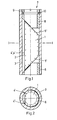
- Dove prism - 1 - (Fig. 1,2), which is preferably ground due to lower manufacturing costs and optically polished on the flat reflecting surface - 2 -, also for reasons of simpler, therefore cheaper, but also more precise manufacture , a circular cylindrical, very internally ground support - 3 -.
- the Dove prism lies on the inner surface of the carrier 3 along the prism edges 4 ′, 4 ′′ formed by the reflecting surface 2 with the cylinder jacket.
- On one end face 5 '- is the Dove prism - 1 - on a region of a ring-cylindrical clamping means - 6 - firmly connected to the support - 3 - on and on the other end face - 5 "- is a multi-part clamping means - 7 - with one region of its circular support element - 8 - on the Dove prism - 1 - on.
- This support element - 8 - is elastically countered by a ring - 9 - which can be screwed into the carrier - 3 - by means of an O-ring - 10 - located between the two the Dove prism - 1 - pressed.
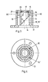
- a prism socket (Fig. 3,4) for a deflecting prism - 11 - has as a support - 12 - a tube which carries a flange - 13 - on one end face. This is used on the one hand as a fastening flange for the prism holder and on the other hand as a clamping means firmly connected to the tube, in that the inside diameter of the flange opening - 14 - is smaller than the diagonal of the surface of the deflecting prism - 11 - resting on it. As a result, the prism only rests on the flange in the area of its corners.
- This deflecting prism - 11 - is mounted in an annular-cylindrical sleeve - 15 - inserted in the tube by virtue of the fact that it has two of the edges - 16 ', 16 "- which are determined by the surfaces not resting on the flange, perpendicular to it rest on the inner cylinder surface, this sleeve being pierced in the area of the beam exit surface.
- the sleeve - 15 - is secured by a worm screw - 21 - which engages in a groove.
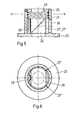
- a frame for another deflection prism (Fig. 5,6) is constructed similarly to the frame according to FIGS. 3 and 4.
- a circular-cylindrical carrier - 22 - which has a flange - 23 - with a circular opening - 24 -
- a two-part deflecting prism - 26 - is inserted so that it is on the one hand with the radiation entry surface, the one Diagonally larger than the diameter of the opening - 24 -, rests on the flange - 23 - and on the other hand with two contact edges - 27 ', 27 "- the beam exit surface rests against the inner wall of the sleeve first spring - 28 - pressed against the sleeve and held on the surface opposite the radiation entry surface by a second spring - 29 -, which rests on the corner regions of the prism, against the flange - 23 -, the second spring being held on a detachable retaining ring - 25 - supports.
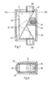
- a frame for a straight view prism - 31 - (Fig. 7,8) this lies with two support edges - 32 ', 32 "- the reflection surface - 33 - in a U-shaped support - 34 - in the region of the curvature and is held by a multi-part clamping means, which is essentially designed as a cover - 36 -
- an O-ring - 39 '- is arranged in the cover on one side, which lies against the prism and holds it axially.
- prism holders What is common to these prism holders is that the prism lies against a support along two support edges and is held in such a way that its support is statically determined and self-aligning, i.e. that there are two degrees of freedom of clamping.
- This type of frame is not limited to prisms. It can be used for all correspondingly shaped or mouldable optical components.
- the fixtures and gauges for adjustment and reworking are also omitted in this version.
- smaller frame dimensions are possible in comparable cases, and yet a higher level of insensitivity to impact, vibration and temperature stresses has been achieved, as tests have shown.
- the optically effective surface is always parallel to the mechanical frame axis, which often serves as the axis of rotation of the component. After the installation of the optical component, all adjustment work is no longer necessary; the accuracy is achieved through the individual processing of the individual parts and not, as was previously the case, through adjustment and rework.
Landscapes
- Physics & Mathematics (AREA)
- General Physics & Mathematics (AREA)
- Optics & Photonics (AREA)
- Mounting And Adjusting Of Optical Elements (AREA)
- Optical Couplings Of Light Guides (AREA)
Priority Applications (1)
| Application Number | Priority Date | Filing Date | Title |
|---|---|---|---|
| AT82105021T ATE25432T1 (de) | 1981-06-11 | 1982-06-08 | Fassung fuer ein prismatisches, optisches bauteil. |
Applications Claiming Priority (2)
| Application Number | Priority Date | Filing Date | Title |
|---|---|---|---|
| CH3853/81A CH651399A5 (de) | 1981-06-11 | 1981-06-11 | Fassung fuer ein prismatisches, optisches bauteil. |
| CH3853/81 | 1981-06-11 |
Publications (3)
| Publication Number | Publication Date |
|---|---|
| EP0067405A2 true EP0067405A2 (fr) | 1982-12-22 |
| EP0067405A3 EP0067405A3 (en) | 1983-10-12 |
| EP0067405B1 EP0067405B1 (fr) | 1987-02-04 |
Family
ID=4264880
Family Applications (1)
| Application Number | Title | Priority Date | Filing Date |
|---|---|---|---|
| EP82105021A Expired EP0067405B1 (fr) | 1981-06-11 | 1982-06-08 | Support pour un élément optique prismatique |
Country Status (5)
| Country | Link |
|---|---|
| US (1) | US4571028A (fr) |
| EP (1) | EP0067405B1 (fr) |
| AT (1) | ATE25432T1 (fr) |
| CH (1) | CH651399A5 (fr) |
| DE (1) | DE3275412D1 (fr) |
Cited By (5)
| Publication number | Priority date | Publication date | Assignee | Title |
|---|---|---|---|---|
| EP0162961A3 (fr) * | 1984-04-27 | 1988-03-02 | Siemens Aktiengesellschaft | Fixage d'un élément optique |
| DE3634196A1 (de) * | 1986-10-08 | 1988-04-21 | Zeiss Carl Fa | Einrichtung zur verbindung zweier koerper mit unterschiedlichen thermischen ausdehnungskoeffizienten |
| US5418769A (en) * | 1992-01-30 | 1995-05-23 | Canon Kabushiki Kaisha | Beam splitter |
| EP0816889A1 (fr) * | 1996-07-01 | 1998-01-07 | HE HOLDINGS, INC. dba HUGHES ELECTRONICS | Support pour composants optiques |
| US8277645B2 (en) | 2008-12-17 | 2012-10-02 | Jarvis Jr Ernest | Automatic retractable screen system for storm drain inlets |
Families Citing this family (9)
| Publication number | Priority date | Publication date | Assignee | Title |
|---|---|---|---|---|
| US4727859A (en) * | 1986-12-29 | 1988-03-01 | Welch Allyn, Inc. | Right angle detachable prism assembly for borescope |
| GB9210488D0 (en) * | 1992-05-15 | 1992-07-01 | British Tech Group | Mechanical mounting |
| US6271514B1 (en) * | 1999-03-19 | 2001-08-07 | Etec Systems, Inc. | Multi-beam scanner including a dove prism array |
| US6775077B1 (en) * | 2000-09-22 | 2004-08-10 | Symbol Technologies, Inc. | Micro reader scan engine with prism |
| US6873479B2 (en) * | 2003-04-30 | 2005-03-29 | Eastman Kodak Company | Mounting bracket for a clear aperture of the base face of a prism |
| JP4651476B2 (ja) * | 2005-07-29 | 2011-03-16 | 株式会社リコー | 光走査装置の組立方法および光走査装置ならびに画像形成装置 |
| EP2171505B1 (fr) * | 2007-06-26 | 2019-10-16 | Rolls-Royce Corporation | Support de prisme pour un dispositif de dépôt laser |
| EP2388145A1 (fr) * | 2010-05-20 | 2011-11-23 | NanoSec Gesellschaft für Nanotechnologie in der Sicherheitstechnik mbH | Unité de miroir de déviation et dispositif d'écriture au laser à l'aide d'une telle unité de déviation |
| CN113960744B (zh) * | 2021-11-05 | 2023-09-12 | 中国工程物理研究院机械制造工艺研究所 | 用于装夹楔形镜的夹具、楔形镜及一种光学器件 |
Family Cites Families (9)
| Publication number | Priority date | Publication date | Assignee | Title |
|---|---|---|---|---|
| US904066A (en) * | 1908-11-17 | Optische Anstalt Goerz Ag | Prism-telescope and similar prism-carrying device and means for adjusting the prisms. | |
| US1821623A (en) * | 1931-04-13 | 1931-09-01 | Harold S Holmes | Light condensing optical system |
| GB651732A (en) * | 1947-02-06 | 1951-04-11 | Optique Soc Gen | Means for fastening prisms in optical instruments |
| CH442791A (de) * | 1966-12-06 | 1967-08-31 | Contraves Ag | Fassung für Rotationskörper, insbesondere optische Linsen, Spiegel oder Winkelmessscheiben |
| FR2044159A5 (fr) * | 1969-05-09 | 1971-02-19 | Comp Generale Electricite | |
| DE2140317C3 (de) * | 1971-08-11 | 1978-09-28 | Siemens Ag, 1000 Berlin Und 8000 Muenchen | Halterung für einen quaderförmigen Kristall |
| US3796098A (en) * | 1972-04-19 | 1974-03-12 | F Trayer | Liquid level gauge |
| FR2252584B3 (fr) * | 1973-11-23 | 1976-10-08 | Ulmic Sa | |
| JPS5365726A (en) * | 1976-11-24 | 1978-06-12 | Canon Inc | Penta-prism fixing device |
-
1981
- 1981-06-11 CH CH3853/81A patent/CH651399A5/de not_active IP Right Cessation
-
1982
- 1982-06-03 US US06/384,635 patent/US4571028A/en not_active Expired - Fee Related
- 1982-06-08 DE DE8282105021T patent/DE3275412D1/de not_active Expired
- 1982-06-08 EP EP82105021A patent/EP0067405B1/fr not_active Expired
- 1982-06-08 AT AT82105021T patent/ATE25432T1/de not_active IP Right Cessation
Cited By (7)
| Publication number | Priority date | Publication date | Assignee | Title |
|---|---|---|---|---|
| EP0162961A3 (fr) * | 1984-04-27 | 1988-03-02 | Siemens Aktiengesellschaft | Fixage d'un élément optique |
| DE3634196A1 (de) * | 1986-10-08 | 1988-04-21 | Zeiss Carl Fa | Einrichtung zur verbindung zweier koerper mit unterschiedlichen thermischen ausdehnungskoeffizienten |
| US5418769A (en) * | 1992-01-30 | 1995-05-23 | Canon Kabushiki Kaisha | Beam splitter |
| EP0558184B1 (fr) * | 1992-01-30 | 1998-05-20 | Canon Kabushiki Kaisha | Tête optique comprenant un séparateur de faisceaux |
| EP0816889A1 (fr) * | 1996-07-01 | 1998-01-07 | HE HOLDINGS, INC. dba HUGHES ELECTRONICS | Support pour composants optiques |
| US5737346A (en) * | 1996-07-01 | 1998-04-07 | Hughes Electronics | Mount for optical components |
| US8277645B2 (en) | 2008-12-17 | 2012-10-02 | Jarvis Jr Ernest | Automatic retractable screen system for storm drain inlets |
Also Published As
| Publication number | Publication date |
|---|---|
| CH651399A5 (de) | 1985-09-13 |
| EP0067405A3 (en) | 1983-10-12 |
| EP0067405B1 (fr) | 1987-02-04 |
| DE3275412D1 (en) | 1987-03-12 |
| US4571028A (en) | 1986-02-18 |
| ATE25432T1 (de) | 1987-02-15 |
Similar Documents
| Publication | Publication Date | Title |
|---|---|---|
| EP0067405B1 (fr) | Support pour un élément optique prismatique | |
| DE2233639A1 (de) | Halterung fuer optische bauelemente, insbesondere in einem lasersystem | |
| DE1952128C3 (de) | Verfahren zur Herstellung eines Farbteilers | |
| DE2717299C2 (de) | Vorrichtung zur Aufnahme und zum Antrieb eines Polygonspiegels | |
| EP0124631A1 (fr) | Dispositif pour engendrer un rayon de visée optique | |
| DE1622122A1 (de) | Verfahren und Anordnung zum justierbaren Montieren von optischen Elementen | |
| EP3765883B1 (fr) | Monture d'ajustage conçue pour réaliser l'ajustage radial d'une unité optique présentant un axe optique | |
| EP0573806A1 (fr) | Balance de précision | |
| DE19517423A1 (de) | Vorrichtung zur Einstellung des Brennpunktabstandes von der Linsenrückseite für eine Videokamera | |
| DE3835061A1 (de) | Bildeingabeeinrichtung | |
| DE102021107413B3 (de) | Kompakte Justierfassung zur Justierung von zwei optischen Tuben | |
| EP1666944B1 (fr) | Coupleur à fibre optique | |
| DE69524392T2 (de) | Linsenhalterung | |
| DE7537569U (de) | Fotografisches objektiv | |
| EP0289693A1 (fr) | Objectif interchangeable pour caméra de cinéma | |
| WO2003087944A2 (fr) | Dispositif de logement à faible déformation d'un élément optique à révolution non symétrique | |
| DE20203475U1 (de) | Befestigungsvorrichtung | |
| DE3627687A1 (de) | Vorrichtung zum justieren eines optischen kollimators | |
| DE1289331B (de) | Brille mit einem Vergroesserungsaufsatz | |
| EP0703482A1 (fr) | Dispositif d'affichage à cellules séparées | |
| DE4408115B4 (de) | Umlenkspiegelgehäuse für Lasermaterialbearbeitungssysteme | |
| DE1961913A1 (de) | Feineinstellvorrichtung,insbesondere Justiervorrichtung fuer im Strahlengang von Lasern angeordneten Blenden | |
| DE2501178A1 (de) | Prismenstuhl fuer zweiteilige prismensaetze | |
| DE102009056659A1 (de) | Objektiv für eine Halbleiterkamera und Verfahren zum Fokussieren einer Halbleiterkamera | |
| DE2714494A1 (de) | Justiervorrichtung fuer ein optisches element |
Legal Events
| Date | Code | Title | Description |
|---|---|---|---|
| PUAI | Public reference made under article 153(3) epc to a published international application that has entered the european phase |
Free format text: ORIGINAL CODE: 0009012 |
|
| AK | Designated contracting states |
Designated state(s): AT DE FR GB IT SE |
|
| PUAL | Search report despatched |
Free format text: ORIGINAL CODE: 0009013 |
|
| AK | Designated contracting states |
Designated state(s): AT DE FR GB IT SE |
|
| 17P | Request for examination filed |
Effective date: 19840404 |
|
| GRAA | (expected) grant |
Free format text: ORIGINAL CODE: 0009210 |
|
| AK | Designated contracting states |
Kind code of ref document: B1 Designated state(s): AT DE FR GB IT SE |
|
| REF | Corresponds to: |
Ref document number: 25432 Country of ref document: AT Date of ref document: 19870215 Kind code of ref document: T |
|
| REF | Corresponds to: |
Ref document number: 3275412 Country of ref document: DE Date of ref document: 19870312 |
|
| ITF | It: translation for a ep patent filed | ||
| ET | Fr: translation filed | ||
| PLBE | No opposition filed within time limit |
Free format text: ORIGINAL CODE: 0009261 |
|
| STAA | Information on the status of an ep patent application or granted ep patent |
Free format text: STATUS: NO OPPOSITION FILED WITHIN TIME LIMIT |
|
| 26N | No opposition filed | ||
| PG25 | Lapsed in a contracting state [announced via postgrant information from national office to epo] |
Ref country code: GB Effective date: 19880608 Ref country code: AT Effective date: 19880608 |
|
| PG25 | Lapsed in a contracting state [announced via postgrant information from national office to epo] |
Ref country code: SE Effective date: 19880609 |
|
| GBPC | Gb: european patent ceased through non-payment of renewal fee | ||
| PG25 | Lapsed in a contracting state [announced via postgrant information from national office to epo] |
Ref country code: FR Free format text: LAPSE BECAUSE OF NON-PAYMENT OF DUE FEES Effective date: 19890228 |
|
| PG25 | Lapsed in a contracting state [announced via postgrant information from national office to epo] |
Ref country code: DE Effective date: 19890301 |
|
| REG | Reference to a national code |
Ref country code: FR Ref legal event code: ST |
|
| EUG | Se: european patent has lapsed |
Ref document number: 82105021.8 Effective date: 19890220 |