EP0067427A2 - Procédé d'aspiration de gaz dans les mines de charbon et tuyau d'aspiration pour réaliser ce procédé - Google Patents
Procédé d'aspiration de gaz dans les mines de charbon et tuyau d'aspiration pour réaliser ce procédé Download PDFInfo
- Publication number
- EP0067427A2 EP0067427A2 EP19820105105 EP82105105A EP0067427A2 EP 0067427 A2 EP0067427 A2 EP 0067427A2 EP 19820105105 EP19820105105 EP 19820105105 EP 82105105 A EP82105105 A EP 82105105A EP 0067427 A2 EP0067427 A2 EP 0067427A2
- Authority
- EP
- European Patent Office
- Prior art keywords
- suction pipe
- cartridge
- suction
- plastic
- wall
- Prior art date
- Legal status (The legal status is an assumption and is not a legal conclusion. Google has not performed a legal analysis and makes no representation as to the accuracy of the status listed.)
- Withdrawn
Links
- 238000000034 method Methods 0.000 title claims abstract description 23
- 238000005065 mining Methods 0.000 title claims description 5
- 239000003245 coal Substances 0.000 title claims description 4
- 239000004033 plastic Substances 0.000 claims abstract description 44
- 229920003023 plastic Polymers 0.000 claims abstract description 44
- 238000005187 foaming Methods 0.000 claims abstract description 29
- 238000007789 sealing Methods 0.000 claims description 17
- 239000007788 liquid Substances 0.000 claims description 4
- 230000007704 transition Effects 0.000 claims description 3
- 238000005553 drilling Methods 0.000 claims description 2
- 229920001971 elastomer Polymers 0.000 claims description 2
- 239000012528 membrane Substances 0.000 claims description 2
- 230000002787 reinforcement Effects 0.000 claims description 2
- 239000002184 metal Substances 0.000 claims 1
- 238000004080 punching Methods 0.000 claims 1
- 239000006260 foam Substances 0.000 abstract description 6
- 239000003380 propellant Substances 0.000 description 4
- 230000008901 benefit Effects 0.000 description 3
- 230000006378 damage Effects 0.000 description 3
- 239000011435 rock Substances 0.000 description 3
- 230000000694 effects Effects 0.000 description 2
- 238000002347 injection Methods 0.000 description 2
- 239000007924 injection Substances 0.000 description 2
- 229920002635 polyurethane Polymers 0.000 description 2
- 239000004814 polyurethane Substances 0.000 description 2
- 230000004913 activation Effects 0.000 description 1
- 238000010276 construction Methods 0.000 description 1
- 230000007423 decrease Effects 0.000 description 1
- 238000006073 displacement reaction Methods 0.000 description 1
- 238000005259 measurement Methods 0.000 description 1
- 230000007246 mechanism Effects 0.000 description 1
- 230000002028 premature Effects 0.000 description 1
- 238000003825 pressing Methods 0.000 description 1
- 230000008569 process Effects 0.000 description 1
- 238000011084 recovery Methods 0.000 description 1
- 238000010008 shearing Methods 0.000 description 1
- 238000007711 solidification Methods 0.000 description 1
- 230000008023 solidification Effects 0.000 description 1
- 230000008719 thickening Effects 0.000 description 1
Images


Classifications
-
- E—FIXED CONSTRUCTIONS
- E21—EARTH OR ROCK DRILLING; MINING
- E21F—SAFETY DEVICES, TRANSPORT, FILLING-UP, RESCUE, VENTILATION, OR DRAINING IN OR OF MINES OR TUNNELS
- E21F7/00—Methods or devices for drawing- off gases with or without subsequent use of the gas for any purpose
Definitions
- the invention relates to a method for extracting gas in mining, in particular in coal mining, with the steps of drilling a hole in the mountains, inserting a suction pipe formed from rows of pipe sections, sealing the pipe against the bore wall at least at the end on the strut side and the Injecting liquid, foaming plastic into the annular space between the pipe and the bore wall.
- short-circuit area is to be understood as those parts of the borehole from which the longwall atmosphere emerges due to the proximity to the longwall or due to the porosity of the rock which happens to be present as soon as a negative pressure is applied there.
- the invention is seen in the fact that a reservoir for the plastic is attached to each pipe section and that the individual reservoirs are emptied into the annular space with the aid of a remote control.
- the method according to the invention also uses the principle of foaming the annular space between the bore wall and the suction pipe, the plastic is not filled into the annular space in one batch at a time, but instead plastic dumps are present along the suction pipe, which are activated as required for foaming can.
- plastic dumps are present along the suction pipe, which are activated as required for foaming can.
- full foaming can also be carried out at the start of the suction, compared with previously known methods significantly longer foaming lengths can be achieved. So far, the foaming was possible at a maximum length of approx. 8 m, which is primarily due to the fact that the injected liquid plastic begins to foam immediately and due to its increasing solidification and thus due to the increasing friction inside and at the limits of the Annulus the expandability decreases with increasing time since the injection. With the aid of the method according to the invention, however, foaming lengths of 14-20 m can easily be achieved.
- the respective reservoir is arranged in each case in the interior of the pipe section and that the plastic is conducted to the outside via lines.
- the placement of the plastic reservoirs in the interior of the suction tube has the particular advantage that each reservoir is protected from damage and so the emptying into the annular space only takes place when the corresponding remote control has been actuated.
- the free cross-sectional area reduced by the arrangement of the reservoir in the interior of the suction tube can be compensated for either by making the corresponding tube section in the area of the reservoir thicker-bellied or by the reservoir being torn off at a predetermined breaking point and being pulled out of the lower end of the suction tube ; in the latter procedure, however, immediate full foaming is required so that all reservoirs are removed from the suction tube when the suction begins.
- the invention proposes that one or more pipe sections are double-walled to form a reservoir filled with plastic, and that with the aid of a closure operated remotely through the pipe interior outer wall of the double tube can be opened.
- the closure can e.g. cause a displacement of the outer wall relative to the inner and thus an exposure of the plastic enclosed in the annular space of the double-walled tube when the closure is actuated. Deviating from this, deliberate damage in the form of cutting or perforating the outer wall of the double-walled tube is also possible.
- the invention proposes that one or more pipe sections are each provided with at least one line leading from a shut-off device of a plastic-containing cartridge to the outer wall, and that the shut-off device Cartridge consists of a remote-controlled valve.
- the remote control can easily consist of a rope that extends beyond the lower end of the suction pipe and engages an actuating lever of the valve. A tensile force applied to the rope opens the valve, whereby the plastic is emptied into the adjacent annular space between the suction pipe and the bore wall. The actual emptying takes place via a propellant gas located in the cartridge, the filling of which is dimensioned such that the plastic is completely expelled from the cartridge.
- the plastic is allowed to solidify and then another strong pull is exerted on the cable forming the remote control, which breaks the line and the rest of the line, the valve and the Cartridge formed unit can be pulled out of the lower end of the suction tube.
- the predetermined breaking point can be lacing can be generated at the specified point in the line. Deviating from this, the movement of the actuating lever in a first area can also open the valve and in a second area can cut through, for example, the line made of plastic as a result of a cut.
- the valve can also be designed as a compressed air valve, so that instead of the rope there is a hose connection to the valve, which can be activated by connecting a C0 2 cartridge or by connecting to the compressed air network, which is usually already present anyway of the valve can be applied.
- the pressure hose After the associated cartridge has been emptied into the corresponding annular space, the pressure hose also serves as a mechanical pulling device for removing the cartridge with the valve if the removal is necessary or desired.
- a cartridge in every second pipe section is normally sufficient if cartridges of approx. 5 cm diameter and a length of approx. 25 cm and customary dimensions for the borehole and the suction pipe are selected. With other pipe sections of approx. 1.5 m length, there is a satisfactory foaming, but in extreme cases, a normal, i.e. inactive pipe section can also be followed by two pipe sections, each with a cartridge, ie two active pipe sections.
- a particular advantage of this variant of the invention can be seen in the fact that the housing part receiving the piston is provided with a circumferential shoulder arranged below the lines. This shoulder ensures a stroke limitation of the piston, thereby ensuring that the lines leading the plastic outwards cannot be closed by the stroke.
- the annular space surrounding the piston extension underneath the shoulder compared to the piston surface of the piston to be pressurized, enables the foam emerging from the valve not to retract the piston and thus not to cause the valve to close automatically.
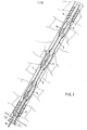
- a suction pipe 2 Arranged within a borehole 1 is a suction pipe 2, which is sealed externally with respect to the borehole 1 against the strut at its lower end by means of a sealing plug 3, for example made of polyurethane.
- the same sealing plug 3 is located just before the suction mouth of the suction pipe. It is composed alternately of active pipe sections 4 and inactive pipe sections 5, sleeves with lip seals being provided at the respective transition points.
- An active pipe section is to be understood as one with a plastic reservoir, in contrast to an inactive pipe section 5, which corresponds to previously known pipe sections.
- the active pipe sections 4 are enlarged in diameter in their central region, so that the plastic reservoir can be accommodated therein without hindering the free passage cross section, which e.g. is predetermined by the inactive pipe sections 5.
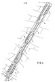
- FIG. 2 A widened section of an active pipe section 4 is shown in FIG. 2.
- a line 9 is attached within a wall 8 by means of collar bushings 10, which is connected to a valve 11 designed as a rotary ball valve.
- the valve 11 is followed by a cartridge 12 filled with a propellant gas and a liquid plastic suitable for foaming, for example polyurethane, which is arranged coaxially to the longitudinal axis of the active pipe section 4.
- the valve 11 is provided with an actuating lever 13 on which a cable 14 engages.
- the rope 14 extends through the entire suction pipe 2 and protrudes from its lower end so far that it is comfortable can be gripped.
- the cable 14 is pulled, whereby the valve 11 is opened.
- the propellant gas inside the cartridge 12 empties the plastic via line 9 into the corresponding annular space, with pre-foaming in line 9 and final foaming outside the line into the annular space.
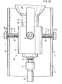
- FIG. 3 shows a view of the widened area of the active pipe section 4 according to FIG. 1.
- the line 9, which is designed as a T-piece, can be clearly seen within the outer wall 8.
- the valve arranged above and the cartridge 12 attached to it is schematically indicated as a circle.
- valve 11 and the cartridge 12 are not arranged coaxially to the longitudinal axis of the active pipe section 4, but rather eccentrically.
- the line 9 is not designed as a T-piece, but as a pure angle piece; there is also only a single opening into the annular space per valve 11 or per cartridge 12.
- FIGS. 1 and 4, 2 and 5 and 3 and 6 correspond, so that with regard to the explanation of the preceding description the corresponding figures can be referenced.
- FIG. 7 differs significantly from the two previously described. It can be seen that the active pipe sections 4 have no widening, that is to say correspond to the inactive pipe sections 5 with regard to their diameter. Nevertheless, they are provided with cartridges 12 (FIG. 8), which would seriously impede the free passage cross section in the position shown. For this reason, the cartridges and the valves must be removed from the interior of the suction pipe 2 after foaming.
- a compressed air valve 18 is provided in this exemplary embodiment, the locking member of which is displaced by the piston of a small pneumatic cylinder.
- a compressed air supply in the form of a hose 19 is required, which is guided through the interior of the suction pipe 2 instead of the cables 14.
- the hose 19 is connected to a pressure source, whereupon the propellant gas in the cartridge 12 pre-foams the plastic and drives it out of the outer wall 8 on both sides through the line 9.
- connection is sufficient, for example, to a C0 2 cartridge with the aid of an appropriate device, as is known, for example, from siphons and the like.
- an appropriate device as is known, for example, from siphons and the like.
- the compressed air supply that is usually present can also be tapped and used to actuate the compressed air valve 18.
- the compressed air valve 18 and the cartridge 12 After the foaming of the annular space around the outer wall 8, the compressed air valve 18 and the cartridge 12 be removed from the interior of the suction pipe 2 so that a usable free passage cross section is available.
- the line 9 is therefore weakened with respect to the diameter at the transition point to the mouth on the outer wall 8 at the points indicated by arrows, as a result of which a predetermined breaking point is present here.
- this predetermined breaking point tears, as a result of which the unit formed from the line residues, the compressed air valve 18 and the cartridge 12 is detached from the outer wall 8 and can be pulled out of the lower end of the exhaust pipe.
- S e stamped l is a predetermined breaking point with the embodiments according to FIGS. 2 and 5 also possible in connection with a cable 14.
- a predetermined breaking point can be present even if the active pipe section 4 has a thickening in the area of the plastic reservoir. It is in fact always possible that a rock falls approximately into the suction mouth of the suction pipe 2 from the inner diameter of the inactive pipe sections 5, which would not fall through the suction pipe 2 without removal, in particular the cartridges 12. In these cases, the general arrangement of a predetermined breaking point is recommended, so that the obstacle for any rocks of larger diameter that may have fallen into the suction pipe can be removed.
- the upper sealing plug 3 When the suction pipe 2 has reached its later desired position, the upper sealing plug 3 already has a considerable friction path from the beginning of the borehole 1 to its later position. The wear is correspondingly strong, so that there is a fear of impairing its sealing effect. For this reason, the pipe section, which carries the upper sealing plug 3, should always be followed by an active pipe section 4, so that the possibly reduced sealing effect by foaming the underneath lying area can be compensated. As a rule, the condition of the upper sealing plug 3 is still so good that the pressing plastic from the foaming process penetrates directly underneath between the sealing plug 3 and the borehole 1, but not into the suction mouth of the suction pipe 2. In this way it is ensured that unintentionally no foam gets into the suction mouth through the foaming in the upper area of the suction pipe 2.
- the third exemplary embodiment (FIGS. 7 and 8) is further developed by the fourth exemplary embodiment according to FIGS. 9 and 10.
- the cartridge 12 has at its lower end a neck 20 which has a tapered cross section compared to the other cartridge cross section.
- a valve housing 21 of the valve 18 which receives the triggering mechanism of the remote control is provided at the lower end with a shoulder 22 which can be inserted into the neck 20 and which has a circumferential groove 24 equipped with a sealing ring 22 for better hold and better sealing within the neck 20.
- the valve housing 21 is formed as a unit in the exemplary embodiment shown in the drawings.
- valve housing 21 with a screw closure that can be attached to the cartridge 12.
- the cartridge 12 connected to the valve housing 21 is fastened via the lines 9 in the wall 8 of an active pipe section 4.
- the lines 9 are designed as axially pierced screws 25, the screw heads 26 being attached to the outside of the wall 8.
- a sealing element 27 is provided between the screw heads 26 and the wall 8.
- the lines 9 are provided with predetermined breaking points 28.
- a piston 29 is attached orders, which is equipped on the top with a valve stem 17 opposite the piston extension 30 for actuation smaller cross-section.
- the housing part 31 is provided with a circumferential shoulder 32 below the lines 9.
- a connection piece 33 is arranged on the valve housing 21, to which the pressure medium line, which can be designed as a hose 19 and can be acted upon by compressed air, is connected by means of a quick-release fastener 34.
- the quick-release fastener 34 makes it possible to produce a fast connection between the pressure medium line and the valve housing 21 which can be subjected to tensile stress, which is important for the recovery of the cartridge 12 from the cased borehole.
- the piston extension 30 is wedge-shaped at its upper end. Furthermore, the screw heads 26 arranged on the outside of the piping are provided with check valves, for example with rubber membranes, in order to prevent the pressed-out plastic from reentering the inside of the piping. In order to avoid tearing off the valve housing 21 inserted into the neck 8 of the cartridge 12 when the cartridge 12 is recovered from the borehole, an additional holder 35 is provided between the valve housing 21 and the cartridge 12. On the circumference of the valve housing 21 there are two fastening elements 36, in the exemplary embodiment shown in FIG. 10, a screw extension, onto which a nut can be screwed, for fastening a holder 35, for example a metallic or plastic flat band, which is around the cartridge 12 is guided around.
- the valve housing 21 connected to the cartridge 12 is arranged fastened to the wall 8 ′ via only one line 9, similar to the second exemplary embodiment according to FIGS. 5 and 6.
- the screw head 26 is arranged in a recess in the wall 8 and on the inside the wall 8, a lock nut 37 is arranged to stabilize the line 9. In this way, premature destruction of the lines 9 is prevented in the event of transverse deformations of the piping or changes in cross-section of the wall 8 of the pipe sections 4.
Landscapes
- Engineering & Computer Science (AREA)
- Mining & Mineral Resources (AREA)
- Life Sciences & Earth Sciences (AREA)
- General Life Sciences & Earth Sciences (AREA)
- Geochemistry & Mineralogy (AREA)
- Geology (AREA)
- Containers And Packaging Bodies Having A Special Means To Remove Contents (AREA)
Applications Claiming Priority (4)
| Application Number | Priority Date | Filing Date | Title |
|---|---|---|---|
| DE19813124044 DE3124044A1 (de) | 1981-06-10 | 1981-06-10 | Verfahren zum absaugen von gas im steinkohlenbergbau und absaugrohr zur durchfuehrung des verfahrens |
| DE3124044 | 1981-06-10 | ||
| DE8135491U | 1981-12-05 | ||
| DE19818135491 DE8135491U1 (de) | 1981-12-05 | 1981-12-05 | Einrichtung zum abdichten verrohrter bohrloecher ueber fernausloeser |
Publications (1)
| Publication Number | Publication Date |
|---|---|
| EP0067427A2 true EP0067427A2 (fr) | 1982-12-22 |
Family
ID=25793953
Family Applications (1)
| Application Number | Title | Priority Date | Filing Date |
|---|---|---|---|
| EP19820105105 Withdrawn EP0067427A2 (fr) | 1981-06-10 | 1982-06-11 | Procédé d'aspiration de gaz dans les mines de charbon et tuyau d'aspiration pour réaliser ce procédé |
Country Status (1)
| Country | Link |
|---|---|
| EP (1) | EP0067427A2 (fr) |
Cited By (11)
| Publication number | Priority date | Publication date | Assignee | Title |
|---|---|---|---|---|
| CN102128047A (zh) * | 2011-01-26 | 2011-07-20 | 湖南省力达能源开发有限公司 | 钻孔施工气碴分离回收系统 |
| CN102251800A (zh) * | 2011-07-13 | 2011-11-23 | 河南理工大学 | 弹夹式封孔器 |
| US8271643B2 (en) | 2006-02-01 | 2012-09-18 | Ca, Inc. | Method for building enterprise scalability models from production data |
| CN104234739A (zh) * | 2014-08-15 | 2014-12-24 | 中国矿业大学 | 一种钻孔内瓦斯爆炸致裂煤体强化抽采方法 |
| CN104747230A (zh) * | 2015-03-02 | 2015-07-01 | 王肇东 | 一种煤矿井瓦斯抽取装置及其使用方法 |
| CN104879088A (zh) * | 2015-05-29 | 2015-09-02 | 辽宁工程技术大学 | 一种针对低渗透松软煤层瓦斯抽采钻孔的充填护孔方法 |
| CN106053161A (zh) * | 2016-07-22 | 2016-10-26 | 中国矿业大学(北京) | 一种采空区瓦斯浓度区域分布三维实测装置与监测方法 |
| CN110925014A (zh) * | 2019-11-14 | 2020-03-27 | 刘云山 | 煤矿注入压力空气快速释放瓦斯的方法 |
| CN111852391A (zh) * | 2020-08-07 | 2020-10-30 | 中煤科工集团重庆研究院有限公司 | 一种自适应变形的瓦斯抽采钻孔封孔装置 |
| CN113931590A (zh) * | 2021-10-25 | 2022-01-14 | 国能神东煤炭集团有限责任公司 | 一种水力切割装置及瓦斯抽采管切割方法 |
| CN114609963A (zh) * | 2022-03-17 | 2022-06-10 | 中煤科工集团沈阳研究院有限公司 | 一种抽采管网数据智能采集与负压分配调控系统及方法 |
-
1982
- 1982-06-11 EP EP19820105105 patent/EP0067427A2/fr not_active Withdrawn
Cited By (14)
| Publication number | Priority date | Publication date | Assignee | Title |
|---|---|---|---|---|
| US8271643B2 (en) | 2006-02-01 | 2012-09-18 | Ca, Inc. | Method for building enterprise scalability models from production data |
| CN102128047B (zh) * | 2011-01-26 | 2013-11-20 | 湖南省力达能源开发有限公司 | 钻孔施工气碴分离回收系统 |
| CN102128047A (zh) * | 2011-01-26 | 2011-07-20 | 湖南省力达能源开发有限公司 | 钻孔施工气碴分离回收系统 |
| CN102251800A (zh) * | 2011-07-13 | 2011-11-23 | 河南理工大学 | 弹夹式封孔器 |
| CN104234739A (zh) * | 2014-08-15 | 2014-12-24 | 中国矿业大学 | 一种钻孔内瓦斯爆炸致裂煤体强化抽采方法 |
| CN104234739B (zh) * | 2014-08-15 | 2016-03-30 | 中国矿业大学 | 一种钻孔内瓦斯爆炸致裂煤体强化抽采方法 |
| CN104747230B (zh) * | 2015-03-02 | 2016-10-19 | 陈宝宝 | 一种煤矿井瓦斯抽取装置及其使用方法 |
| CN104747230A (zh) * | 2015-03-02 | 2015-07-01 | 王肇东 | 一种煤矿井瓦斯抽取装置及其使用方法 |
| CN104879088A (zh) * | 2015-05-29 | 2015-09-02 | 辽宁工程技术大学 | 一种针对低渗透松软煤层瓦斯抽采钻孔的充填护孔方法 |
| CN106053161A (zh) * | 2016-07-22 | 2016-10-26 | 中国矿业大学(北京) | 一种采空区瓦斯浓度区域分布三维实测装置与监测方法 |
| CN110925014A (zh) * | 2019-11-14 | 2020-03-27 | 刘云山 | 煤矿注入压力空气快速释放瓦斯的方法 |
| CN111852391A (zh) * | 2020-08-07 | 2020-10-30 | 中煤科工集团重庆研究院有限公司 | 一种自适应变形的瓦斯抽采钻孔封孔装置 |
| CN113931590A (zh) * | 2021-10-25 | 2022-01-14 | 国能神东煤炭集团有限责任公司 | 一种水力切割装置及瓦斯抽采管切割方法 |
| CN114609963A (zh) * | 2022-03-17 | 2022-06-10 | 中煤科工集团沈阳研究院有限公司 | 一种抽采管网数据智能采集与负压分配调控系统及方法 |
Similar Documents
| Publication | Publication Date | Title |
|---|---|---|
| DE2652901A1 (de) | Vorrichtung und verfahren zur sicherung eines bohrloches | |
| DE69004488T2 (de) | Bodenvernagelung. | |
| EP0546128A1 (fr) | Procede et tuyau d'injection pour la pose de boulons d'ancrage. | |
| DE2935126A1 (de) | Verfahren zum injizieren von moertelschlamm in den erdboden | |
| EP0067427A2 (fr) | Procédé d'aspiration de gaz dans les mines de charbon et tuyau d'aspiration pour réaliser ce procédé | |
| DE1226516B (de) | Verfahren zum zweistufigen Einbetonieren von Gebirgsanker und ein Anker hierfuer | |
| EP0218987A2 (fr) | Méthode pour la mise en place d'un élément de construction au travers d'un rideau de palplanches dans une formation du sol comportant de l'eau sous pression ainsi qu'un dispositif pour la mise en oeuvre de la méthode | |
| EP2496786B1 (fr) | Procédé de forage, en particulier de forage par percussion ou par rotopercussion pour creuser des trous dans le sol ou dans des roches et dispositif associé | |
| DE69624911T2 (de) | Installation eines rohres in eine bestehende rohrleitung | |
| DE1226057B (de) | Anschlussaggregat fuer Tiefbohrungen | |
| DE2544411A1 (de) | Sprengverfahren und vorrichtung zur durchfuehrung des verfahrens | |
| DE2505668A1 (de) | Vorrichtung an bohrausruestungen | |
| DE2800370C2 (de) | Verfahren und Vorrichtung zum Einbauen eines Verpreßankers in eine Bodenformation gegen drückendes Wasser | |
| EP0122924B1 (fr) | Dispositif d'injection | |
| EP1448866B1 (fr) | Procede et dispositif de forage de trous | |
| DE3124044A1 (de) | Verfahren zum absaugen von gas im steinkohlenbergbau und absaugrohr zur durchfuehrung des verfahrens | |
| AT13292U1 (de) | Verfahren und Vorrichtung zum Ausbilden von Bohrlöchern und Festlegen einer Verankerung in dem Bohrloch | |
| DE3545084A1 (de) | Tunnelbauverfahren | |
| DE3407342A1 (de) | Bohrlochverschluss | |
| DE4205152A1 (de) | Vorrichtung zum verschliessen von bohrloechern | |
| DE2829416A1 (de) | Vorrichtung und verfahren zur zementierung von pfeilern fuer bohrinseln | |
| DE69102571T2 (de) | Verfahren und Vorrichtung zum Ablegen eines Steigrohres in einem Zugangsbohrloch einer Salzkaverne für Gasspeicherung. | |
| DE1533680C (fr) | ||
| DE303841C (fr) | ||
| DE102012106855A1 (de) | Vorrichtung und Verfahren zur Probenentnahme |
Legal Events
| Date | Code | Title | Description |
|---|---|---|---|
| PUAI | Public reference made under article 153(3) epc to a published international application that has entered the european phase |
Free format text: ORIGINAL CODE: 0009012 |
|
| AK | Designated contracting states |
Designated state(s): BE DE FR GB |
|
| RBV | Designated contracting states (corrected) |
Designated state(s): BE DE FR GB |
|
| 17P | Request for examination filed |
Effective date: 19830302 |
|
| STAA | Information on the status of an ep patent application or granted ep patent |
Free format text: STATUS: THE APPLICATION HAS BEEN WITHDRAWN |
|
| 18W | Application withdrawn |
Withdrawal date: 19840901 |
|
| RIN1 | Information on inventor provided before grant (corrected) |
Inventor name: GRIMBERG, WILHELM Inventor name: KOPPE, UWE, DR. Inventor name: WEISNER, HORST Inventor name: HEUBACH, HEINZ |