EP0067433A1 - Installation de coulée continue horizontale - Google Patents
Installation de coulée continue horizontale Download PDFInfo
- Publication number
- EP0067433A1 EP0067433A1 EP82105154A EP82105154A EP0067433A1 EP 0067433 A1 EP0067433 A1 EP 0067433A1 EP 82105154 A EP82105154 A EP 82105154A EP 82105154 A EP82105154 A EP 82105154A EP 0067433 A1 EP0067433 A1 EP 0067433A1
- Authority
- EP
- European Patent Office
- Prior art keywords
- mold
- electromagnetic field
- field generating
- molten metal
- tundish nozzle
- Prior art date
- Legal status (The legal status is an assumption and is not a legal conclusion. Google has not performed a legal analysis and makes no representation as to the accuracy of the status listed.)
- Granted
Links
Images





Classifications
-
- B—PERFORMING OPERATIONS; TRANSPORTING
- B22—CASTING; POWDER METALLURGY
- B22D—CASTING OF METALS; CASTING OF OTHER SUBSTANCES BY THE SAME PROCESSES OR DEVICES
- B22D11/00—Continuous casting of metals, i.e. casting in indefinite lengths
- B22D11/10—Supplying or treating molten metal
-
- B—PERFORMING OPERATIONS; TRANSPORTING
- B22—CASTING; POWDER METALLURGY
- B22D—CASTING OF METALS; CASTING OF OTHER SUBSTANCES BY THE SAME PROCESSES OR DEVICES
- B22D11/00—Continuous casting of metals, i.e. casting in indefinite lengths
- B22D11/04—Continuous casting of metals, i.e. casting in indefinite lengths into open-ended moulds
- B22D11/045—Continuous casting of metals, i.e. casting in indefinite lengths into open-ended moulds for horizontal casting
- B22D11/047—Means for joining tundish to mould
Definitions
- This invention relates to a horizontal continuous casting installation for continuously feeding molten metal stored in a tundish through a tundish nozzle secured horizontally to a side wall of the tundish in the vicinity of its bottom to a mold connected to the forward end of the tundish nozzle and arranged coaxially therewith to thereby cast the molten metal in the mold and continuously withdraw from the mold a strand formed therein.
- a horizontal continuous casting installation of the aforesaid construction has been constructed such that the tundish nozzle and the mold are intimately connected to each other to keep a body of molten metal from leaking between the tundish nozzle formed of refractory- material and the mold cooled with water. Because of this, the cooled molten metal has tended to form a shell of solidified molten metal on the outer side of the body of molten metal in the vicinity of the tundish nozzle adjacent the water-cooled mold as the molten metal begins to solidify at its outer side and become adhered to the tundish nozzle.
- the molten metal has tended to invade the refractory material through the pores and become solidified therein, to thereby increase bond strength between the shell and the tundish nozzle.
- the shell formed by solidification of the molten metal undergoes rupture when the strand is withdrawn to thereby give rise to what is generally referred to as a break-out.
- This invention has as one of its objects the provision of a horizontal continuous casting installation on which, in view of the aforesaid problems encountered by horizontal continuous casting installations of the prior art, is capable of preventing a shell of solidified molten metal from adhering to the tundish nozzle by avoiding contact between the molten metal and an inner surface of the tundish nozzle in portion of the tundish nozzle near the mold, to thereby enable a strand to be withdrawn continuously from the mold.
- the aforesaid object can be accomplished according to the invention by providing the horizontal continuous casting installation with electromagnetic field generating means enclosing the tundish nozzle and the mold in the vicinity of the boundary therebetween for exerting an electromagnetic force directed to the center line of a body of molten metal flowing through the vicinity of the boun- ary between the tundish nozzle and the mold on such body of molten metal in such a manner that the electromagnetic force has its intensity increased in going from an upper portion of the body of molten metal toward a lower portion thereof.
- Another object is to provide a horizontal continuous casting installation in which the mold can be made to vibrate back and forth with respect to a direction in which a strand is withdrawn from the mold.
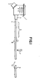
- Fig. 1 shows one example of horizontal continuous casting installation of the prior art for producing steel ingots, showing the construction of the installation as a whole.
- a tundish 1 has a heating device 2 for stabilizing the temperature of a body of molten steel in the tundish 1.
- a strand 4 cast in a mold 3 and released therefrom is withdrawn from a withdrawing zone 5 by a withdrawing device 6 and cut by a cutting device 7 to provide an ingot 9.
- the ingot 9 is transferred by a roller table 10.
- Fig. 2 is a sectional view of an embodiment of the invention incorporated in the installation shown in Fig. 1, showing, on an enlarged scale, a portion of the installation in the vicinity of a tundish nozzle 14 and the mold 3.
- the tundish 1 has a lining of refractory material 11 and stores a body of molten metal 12.
- the tundish 1 has secured thereto a tundish nozzle 14 formed of refractory material connected thereto by a mounting member 13.
- the mold 3 has a cooling liquid passage 15 for achieving water cooling of a mold tube 33 formed of copper, and a strand passage 16 coaxially connected to the tundish nozzle 14 to allow the strand 4 to move therethrough.
- the mold 3 is firmly secured to the tundish nozzle 14.
- Electromagnetic field generating means 18 is located in the vicinity of a boundary 17 between the tundish nozzle 14 and the mold 3 and comprises a first coil 34 and a second coil 35 enclosing the vicinity of the boundary 17 and energized by an AC power.
- a body of molten steel flowing through the vicinity of the boundary 17 has its transverse dimension reduced or is converged in going from its upstream side toward its downstream side by electromagnetic field generated by the electromagnetic field generating means 18, as subsequently to be described in detail by referring to Fig. 3.
- the two coils 34 and 35 constituting the electromagnetic field generating means 18 each comprises a wire wound such that its convolutions enclose the tundish nozzle 14 and a portion of the mold 3 and radially spaced apart from one another.
- the eddy current 38 flows in the opposite direction and exerts a diverging force on the molten steel.
- the energizing current is given with this wave form, it is possible to absorb the component of the region of the curve 62 by forming a bobbin 35' of the coil 35 or the tundish nozzle mounting member 13 shown in Fig. 2 of copper of low electric resistivity, for example.
- a converging force is exerted on the body of molten steel as measured by a mean time of one cycle, as shown in Fig. 3a (2).
- an induced current flows on the surface of the body of molten steel in a direction opposite the direction indicated by an arrow 38 in a region in which the energizing current flows along curves 62 and 62', so that a negative converging force is exerted thereon.
- the region of the curves 62 and 62' in which changes in the current value are great the greater the changes in the value of the energizing current, the more readily absorbed is the induced current by the molten steel or a mold wall.
- the induced current absorbing plate 18' is intended to positively absorb the induced current in the region of the curves 62 and 62'.
- the body of molten steel 12 has its transverse dimention reduced in the vicinity of the boundary 17.
- the aforesaid description regarding the second coil 35 also applies to the first coil 34.
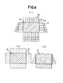
- Fig. 4 shows the distribution of static pressure acting on the body of molten metal 12 flowing through the tundish nozzle 14 and mold 12 and the distributions of a static pressure compensating force and a converging force exerted by the first coil 34 and second coil 35 on the surface of the body of molten steel.
- the distribution of static pressure Pat exerted by the body of molten metal in the vicinity of the boundary 17 between the tundish nozzle 14 and mold 3 is indicated by a line a shown in Fig. 4 (1).
- the distribution of the static pressure compensating force exerted on the surface layer of the body of molten metal is indicated by a line b shown in Fig.
- the first coil 34 generates a static pressure compensating magnetic force shown in Fig. 4 (a).
- the static pressure compensating force P1 shown in Fig. 4 (2) is a total of static pressure Pat and a converging force Qt exerted on the surface of the upper layer of the body of molten steel.
- the first coil 34 has an axis which coincides with those of the tundish nozzle 14 and mold 3.
- the second coil 35 is arranged such that the axis of the coil is located above those of the tundish nozzle 14 and mold 3.
- the magnetic flux density generated in the body of molten metal 12 in the vicinity of the boundary 17 is higher in a lower portion than in an upper portion.
- Fig. 5 (1) is a front view of the second coil 35.as viewed axially thereof
- Fig. 5 (2) shows the distribution of a magnetic flux density in a cross section taken along the line A-A extending through the axis 39 of the second coil 35. In this cross section, it will be seen that the magnetic flux density within the second coil 35 becomes larger in going radially outwardly of the second coil 35.
- the axis 39 of the second coil 35 is located above those of the tundish nozzle 14 and mold, so that the electromagnetic force exerted on the lower layer of the body of molten metal 12 is higher than that exerted on the upper layer thereof.
- an electromagnetic force counteracting the force of gravity acts on the body of molten metal 12 to thereby compensate for the force of gravity.
- the mold 3 is formed with the strand passage 16 having a transverse dimension which becomes smaller in going toward the direction in which the strand 4 is withdrawn from the mold to conform to the contraction of the strand 4 taking place as its solidification progresses, to render cooling of the strand 4 in the mold 3 uniform.
- the tundish nozzle 14 formed with an annular header 41 formed with a nozzle 42 directed radially inwardly of the tundish nozzle 14.
- a lubricant 46 is supplied under pressure to the header 41 through a conduit 43.
- the nozzle 42 is located anterior to a position 44 in which the molten metal 12 is released from the tundish nozzle 14, with respect to a direction 45 in which the strand 4 is withdrawn from the mold 3.
- the lubricant 46 contains as its main ingredient CaO, Si0 2 or AL 2 0 3 in powder form added with pure iron and cobalt in powder form which have good electric conductivity.
- the electromagnetic force directed radially inwardly of the tundish nozzle 14 and mold 3 acts on such powder of good electric conductivity, to allow the lubricant 46 to be positively deposited on the entire outer peripheral surface of the body of molten metal 12 that has been converged in going toward the direction in which the strand 4 is withdrawn from the mold 3, thereby improving the lubricating function of the portion of the body of molten metal 12 that is first brought into contact with the strand passage 16 in the mold 3.
- the lubricant 46 may contain as its main ingredient rapeseed oil added with pure iron and cobalt in powder form.
- a combination of two coils is used for effecting compensation for static pressure positively.
- a single coil 34' which is located in eccentric relation to the strand 4 as is the case with the second coil 35 shown in Fig. 2 may be used with more or less the same effects achieved.
- the electromagnetic field generating means 18 comprises a plurality of electromagnetic field generating elements 50 each including a rod-shaped core 47 extending axially of the tundish nozzle 14 and mold 3 and a coil 49 wound thereon and arranged on an imaginary cylindrical surface surrounding the tundish nozzle 14 and mold 3.
- the electromagnetic field generating elements 50 are arranged closer to one another in a lower portion of the body of molten metal 12 than in an upper portion thereof, so that a magnetic flux of higher density is imparted to the lower portion of the body of molten metal 12 than the upper portion thereof.
- an eddy current is generated in the body of molten metal 12 and flows in the direction of an arrow 52.
- the magnetic field generated by the electromagnetic field generating elements 50 is oriented in a direction indicated by an arrow 53.
- an electromagnetic force tending to act radially inwardly of the body of molten metal 12 has a converging effect on the body of molten metal 12.
- the electromagnetic field generating elements 50 are arranged at a higher density in the lower portion of the body of molten metal 12 than in the upper portion thereof, it is possible to satisfactorily effect compensation for the static pressure form the body of molten metal 12.
- lubricant such as rapeseed oil
- nozzles 55 are arranged annularly in a clearance 56 peripherally thereof between the body of molten metal 12 of reduced transverse dimension and the wall of the strand passage 16.
- Fig. 8 shows, in a sectional view similar to Fig. 7, another embodiment of the invention in which the electromagnetic field generating elements 50 are arranged in a plurality of layers (two layers in this embodiment).
- the numeral 50a designates the first layer of electromagnetic field generating elements located radially inwardly
- the numeral 50b designates the second layer thereof located outwardly. Attention is directed to the arrangement whereby the electromagnetic field generating elements 50a of the first layer are displaced peripherally with respect to the electromagnetic field generating elements 50b of the second layer.
- Fig. 9 is a sectional view showing, on an enlarged scale, a portion of the embodiment shown in Fig. 8.
- the electromagnetic field generating elements 50 may be arranged equidistantly from one another along the periphery of the body of molten metal 12 as shown in Fig. 7a and supply a current of higher value through the lower coils than through the upper coils, or the electromagnetic field generating elements 50 may be arranged equidistantly from one another on an imaginary cylindrical surface as shown in Fig. 7b in such a manner that the imaginary cylindrical surface has an axis displaced upwardly from those of the tundish nozzle 14 and mold 3.
- Fig. 10 is a theoretical sectional view of still another embodiment comprising coils 54 each having a wire wound around the axes of the tundish nozzle 14 and mold 3.
- Each coil 54 has a smaller length as measured axially of the tundish nozzle 14 and mold 3 in its lower portion than in its upper portion, to thereby increase the density of convolutions of the wire, to thereby give a higher density of magnetic flux to the lower portion of the body of molten metal 12 than to the upper portion thereof.
- static pressure compensation can be effected with increased positiveness for the molten metal 12.
- the second coil 35 is displaced with respect to the tundish nozzle 14 and mold 3 and arranged in the same manner as described by referring to the embodiment shown and described hereinabove.
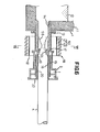
- Fig. 11 is a vertical sectional view of still another embodiment
- Fig. 12 is a top plan view of the embodiment shown in Fig. 11.
- parts similar to those shown in Figs. 1-10 are designated by like reference characters.
- the truck 23 is urged by the biasing force of a compression spring 24 to move in the direction 45 and moved back and forth with regard to the strand withdrawing direction 45 by an eccentric cam 26 driven by a motor 25 to move in vibratory movement.
- the truck 23 also supports thereon the electromagnetic field generating means 18.
- the lubricant 46 is fed through the nozzles 42 to the body of molten metal 12 of reduced transverse dimension to be deposited on the entire outer peripheral surface thereof, to thereby positively effect lubrication of the body of molten metal 12 and avoid oxidization thereof.
- the mold 3 and the tundish nozzle 14 are spaced apart from each other by a clearance 28 to move the mold 3 back and forth in vibratory movement with respect to the direction 45 in which the strand 4 is withdrawn from the mold 3.
- This is conducive to prevention of adhesion of a shell of solidified molten metal to the tundish nozzle 14 and mold 3 and rapid cooling of the strand 4, thereby enabling continuous withdrawing of the strand 4 to be effected smoothly.
- the tundish nozzle 14 has a greater transverse dimension on a side thereof adjacent the mold 3 than on a side thereof adjacent the tundish 1.
- airtightly sealing means 27 such as a bellows of flexibility, may be used to provide an airtight seal to the clearance 28 between the tundish nozzle 14 and mold 3, to keep the surface of the body of molten metal 12 of reduced transverse dimension from being oxidized.
- Inert gas such as argon, nitrogen, etc., may be supplied through a conduit 29 to the interior of the airtightly sealing means 27.
- F ig. 13 shows further embodiment, in cross section, in which the tundish nozzle 14 is composed of a plurality of portions 14a and 14b, to thereby facilitate fabrication of the tundish nozzle 14 of large cross section or complicated cross section.
- Other parts of the embodiment shown in Fig. 13 are similar to those of embodiments shown in Figs. 1-12.
- the electromagnetic field generating means 18 is supported on the truck 23 and moved in vibratory movement together with the mold 3 as a unit. However, this is not essential and the electromagnetic field generating means 18 may be securedly fixed without being moved.
- the truck 23 is moved in vibratory movement by the eccentric cam 26, but the eccentric cam 26 may be replaced by a crank mechanism or a double acting hydraulic cylinder.
- the invention When the invention is incorporated in the prior art in which, as described in Japanese Patent No. Sho-50-27448, a ring of boron nitride or silicon nitride is mounted in the tundish nozzle portion to carry out intermittent withdrawing of a strand from the mold, the invention has the effect of elongating the service lives of these rings.
- lubricant in powder form has been described as being supplied to the body of molten metal in the vicinity of the position in which a reduction in the transverse dimension of the body of molten metal is initiated or lubricant has been described as being sprayed on to the body of molten metal in a portion thereof which is first brought into contact with the wall of the mold.
- a protective layer 19 formed of non-porous boron nitride or silicon nitride of high lubricating function may be mounted in the strand passage 16 of the mold 3 in the vicinity of the boundary 17 in which the body of molten metal 12 of reduced transverse direction is first brought into contact with the wall of the passage 16, and another protective layer 20 formed of carbon and having high lubricating function may be mounted downstream of the protective layer 19 with respect to the strand withdrawing direction, as shown in Fig. 6. This is conducive to prevention of adhesion of a shell of solidified molten metal to the wall of the strand passage 16 of the mold 3, thereby permitting the strand 4 to be smoothly and continuously withdrawn from the mold 3.
- the invention can have application not only to steel but also to any metal in molten state to cast same over a wide range so long as the metal has electric conductivity.
- electromagnetic field generating means is used for exerting a converging force on a body of molten metal to reduce its transverse dimension in the vicinity of the boundary between the tundish nozzle and mold, to avoid contact of the body of the molten metal with the tundish nozzle and keep a shell of solidified molten metal from adhering to the tundish nozzle.
- This is conducive to prevention of wear that might otherwise be caused on the tundish nozzle.
- the invention thus enables a horizontal continuous casting installation to carry out continuous withdrawing of a strand without any trouble.
- the mold may be moved in vibratory movement back and forth with respect to the direction in which the strand is withdrawn from the mold.
- the electromagnetic field generating means according to the invention is capable to generating a magnetic flux of higher density in a lower portion of a body of molten metal than in an upper portion thereof.
- compensation for static pressure applied to the body of molten metal of reduced transverse dimension can be positively effected, and the body of molten metal can be allowed to flow with substantially the same cross-sectional configuration as the mold while its axis is kept substantially in agreement with the axis of the mold. This is conducive to improved quality of a strand produced by horizontal continuous casting.
Landscapes
- Engineering & Computer Science (AREA)
- Mechanical Engineering (AREA)
- Continuous Casting (AREA)
Applications Claiming Priority (2)
| Application Number | Priority Date | Filing Date | Title |
|---|---|---|---|
| JP94333/81 | 1981-06-17 | ||
| JP56094333A JPS57209752A (en) | 1981-06-17 | 1981-06-17 | Horizontal continuous casting installation |
Publications (3)
| Publication Number | Publication Date |
|---|---|
| EP0067433A1 true EP0067433A1 (fr) | 1982-12-22 |
| EP0067433B1 EP0067433B1 (fr) | 1985-02-20 |
| EP0067433B2 EP0067433B2 (fr) | 1989-08-16 |
Family
ID=14107347
Family Applications (1)
| Application Number | Title | Priority Date | Filing Date |
|---|---|---|---|
| EP82105154A Expired EP0067433B2 (fr) | 1981-06-17 | 1982-06-12 | Installation de coulée continue horizontale |
Country Status (5)
| Country | Link |
|---|---|
| US (1) | US4601327A (fr) |
| EP (1) | EP0067433B2 (fr) |
| JP (1) | JPS57209752A (fr) |
| KR (1) | KR870000053B1 (fr) |
| DE (1) | DE3262409D1 (fr) |
Cited By (5)
| Publication number | Priority date | Publication date | Assignee | Title |
|---|---|---|---|---|
| EP0191586A1 (fr) * | 1985-02-13 | 1986-08-20 | Sumitomo Light Metal Industries Limited | Coulée continue horizontale utilisant un champ électromagnétique supportant le lingot coulé |
| WO1987001632A1 (fr) * | 1985-09-13 | 1987-03-26 | Erik Olsson Ag | Procede et dispositif de coulee continue |
| EP0223229A1 (fr) * | 1985-11-21 | 1987-05-27 | Asea Ab | Méthode et dispositif de coulée continue horizontale |
| US5595237A (en) * | 1993-03-30 | 1997-01-21 | Mannesmann Aktiengesellschaft | Horizontal continuous casting apparatus for metals |
| CN1060978C (zh) * | 1995-12-19 | 2001-01-24 | 西安工业学院 | 金属基复合材料水平连铸方法与设备 |
Families Citing this family (11)
| Publication number | Priority date | Publication date | Assignee | Title |
|---|---|---|---|---|
| JPS6114050A (ja) * | 1984-06-28 | 1986-01-22 | Kawasaki Heavy Ind Ltd | 水平連続鋳造用タンデイツシユ |
| US4842170A (en) * | 1987-07-06 | 1989-06-27 | Westinghouse Electric Corp. | Liquid metal electromagnetic flow control device incorporating a pumping action |
| RU2162769C2 (ru) * | 1997-05-28 | 2001-02-10 | Лев Петрович Фридман | Устройство для непрерывного литья |
| US6341642B1 (en) | 1997-07-01 | 2002-01-29 | Ipsco Enterprises Inc. | Controllable variable magnetic field apparatus for flow control of molten steel in a casting mold |
| CA2242037C (fr) * | 1997-07-01 | 2004-01-27 | Ipsco Inc. | Dispositif a champ magnetique controlable et variable pour limiter l'ecoulement de l'acier liquide dans un moule |
| JP3836362B2 (ja) * | 2001-02-02 | 2006-10-25 | Juki株式会社 | ミシンの糸調子装置 |
| CN104107889B (zh) * | 2013-04-16 | 2016-02-10 | 沈阳华铸科技有限公司 | 大断面球墨铸铁水平连铸生产工艺及其石墨模具装置 |
| WO2015179680A2 (fr) | 2014-05-21 | 2015-11-26 | Novelis Inc. | Buse d'éjecteur mélangeur et dispositif de régulation de débit |
| CN104057039A (zh) * | 2014-06-19 | 2014-09-24 | 无锡隆达金属材料有限公司 | 热冷组合型水平连铸专用内冷式封炉压板 |
| EP3191237A4 (fr) * | 2014-09-12 | 2018-06-06 | Imerys Graphite & Carbon Switzerland S.A. | Ameliorations dans des procedes et systemes necessitant une lubrification |
| JP7735699B2 (ja) * | 2021-07-13 | 2025-09-09 | 株式会社レゾナック | 水平連続鋳造装置、アルミニウム合金鋳造棒の製造方法 |
Citations (4)
| Publication number | Priority date | Publication date | Assignee | Title |
|---|---|---|---|---|
| DE2239531A1 (de) * | 1971-08-12 | 1973-02-22 | Technicon Instr | Verfahren und vorrichtung zum kontinuierlichen giessen von werkstuecken aus metall |
| US3987840A (en) * | 1973-11-28 | 1976-10-26 | Institut De Recherches De La Siderurgie Francaise (Irsid) | Method and apparatus for continuously casting of metal in horizontal direction |
| FR2423284A1 (fr) * | 1978-04-20 | 1979-11-16 | Arbed | Methode et dispositif pour la coulee continue horizontale et la coulee continue avec lingotiere inclinee |
| DE2756112B2 (de) * | 1976-12-17 | 1981-06-11 | Concast AG, Zürich | Verfahren und Vorrichtung zum horizontalen Stranggießen |
Family Cites Families (4)
| Publication number | Priority date | Publication date | Assignee | Title |
|---|---|---|---|---|
| US3630266A (en) * | 1969-11-21 | 1971-12-28 | Technicon Corp | Continuous casting process |
| JPS5027448A (fr) * | 1973-07-10 | 1975-03-20 | ||
| DE2722969A1 (de) * | 1976-05-24 | 1977-12-15 | Bailey Ltd C H | Schwimmdock |
| CH648500A5 (de) * | 1980-07-11 | 1985-03-29 | Concast Ag | Verfahren und vorrichtung zum stranggiessen von metall in einem geschlossenen eingiesssystem. |
-
1981
- 1981-06-17 JP JP56094333A patent/JPS57209752A/ja active Pending
-
1982
- 1982-06-12 DE DE8282105154T patent/DE3262409D1/de not_active Expired
- 1982-06-12 EP EP82105154A patent/EP0067433B2/fr not_active Expired
- 1982-06-14 US US06/388,399 patent/US4601327A/en not_active Expired - Lifetime
- 1982-06-17 KR KR8202689A patent/KR870000053B1/ko not_active Expired
Patent Citations (4)
| Publication number | Priority date | Publication date | Assignee | Title |
|---|---|---|---|---|
| DE2239531A1 (de) * | 1971-08-12 | 1973-02-22 | Technicon Instr | Verfahren und vorrichtung zum kontinuierlichen giessen von werkstuecken aus metall |
| US3987840A (en) * | 1973-11-28 | 1976-10-26 | Institut De Recherches De La Siderurgie Francaise (Irsid) | Method and apparatus for continuously casting of metal in horizontal direction |
| DE2756112B2 (de) * | 1976-12-17 | 1981-06-11 | Concast AG, Zürich | Verfahren und Vorrichtung zum horizontalen Stranggießen |
| FR2423284A1 (fr) * | 1978-04-20 | 1979-11-16 | Arbed | Methode et dispositif pour la coulee continue horizontale et la coulee continue avec lingotiere inclinee |
Cited By (6)
| Publication number | Priority date | Publication date | Assignee | Title |
|---|---|---|---|---|
| EP0191586A1 (fr) * | 1985-02-13 | 1986-08-20 | Sumitomo Light Metal Industries Limited | Coulée continue horizontale utilisant un champ électromagnétique supportant le lingot coulé |
| US4694888A (en) * | 1985-02-13 | 1987-09-22 | Sumitomo Light Metal Industries, Ltd. | Electromagnetic levitation casting |
| WO1987001632A1 (fr) * | 1985-09-13 | 1987-03-26 | Erik Olsson Ag | Procede et dispositif de coulee continue |
| EP0223229A1 (fr) * | 1985-11-21 | 1987-05-27 | Asea Ab | Méthode et dispositif de coulée continue horizontale |
| US5595237A (en) * | 1993-03-30 | 1997-01-21 | Mannesmann Aktiengesellschaft | Horizontal continuous casting apparatus for metals |
| CN1060978C (zh) * | 1995-12-19 | 2001-01-24 | 西安工业学院 | 金属基复合材料水平连铸方法与设备 |
Also Published As
| Publication number | Publication date |
|---|---|
| DE3262409D1 (en) | 1985-03-28 |
| KR870000053B1 (ko) | 1987-02-09 |
| EP0067433B2 (fr) | 1989-08-16 |
| EP0067433B1 (fr) | 1985-02-20 |
| US4601327A (en) | 1986-07-22 |
| KR840000305A (ko) | 1984-02-18 |
| JPS57209752A (en) | 1982-12-23 |
Similar Documents
| Publication | Publication Date | Title |
|---|---|---|
| EP0067433B2 (fr) | Installation de coulée continue horizontale | |
| US4146078A (en) | Method of and apparatus for continuous horizontal casting | |
| US4353408A (en) | Electromagnetic thin strip casting apparatus | |
| EP0007581B1 (fr) | Assemblage de moule et procédé de coulée continue de fils métalliques à des vitesses exceptionnellement élevées | |
| US4137961A (en) | Continuous casting of metals | |
| US4736789A (en) | Apparatus and method for continuous casting of metallic strands at exceptionally high speeds using an oscillating mold assembly | |
| US3642055A (en) | Method of and apparatus for continuously casting molten metal | |
| US3284859A (en) | Circular trough casting apparatus | |
| EP0068402B1 (fr) | Installation de coulée continue horizontale | |
| PT83360B (pt) | Processo e aparelho de vazamento continuo | |
| EP0034719B1 (fr) | Procédé et appareil pour la coulée continue de barres métalliques | |
| US4307770A (en) | Mold assembly and method for continuous casting of metallic strands at exceptionally high speeds | |
| JPH0683888B2 (ja) | 加圧鋳造装置 | |
| US6520246B2 (en) | Method and device for continuous casting of molten materials | |
| US4375234A (en) | Electromagnetic thin strip casting process | |
| JPH04178247A (ja) | 電磁界を有する鋳型による鋼の連続鋳造方法 | |
| EP0042995B1 (fr) | Appareil et procédé pour la coulée continue de fils métalliques à des vitesses exceptionnellement élevées utilisant un moule oscillant | |
| JPH0120942B2 (fr) | ||
| JPS6123557A (ja) | 連続鋳造機 | |
| JPH07204789A (ja) | 金属の連続鋳造用湾曲鋳型 | |
| JPH0417949A (ja) | 中空鋳片の連続鋳造装置 | |
| FI94224B (fi) | Sähkömagneettinen levitaatiotyyppinen jatkuvatoiminen metallivalulaite | |
| JPH02307651A (ja) | 金属の連続製造装置 | |
| JPS6210743B2 (fr) | ||
| JPS58212842A (ja) | 金属薄板の連続鋳造方法 |
Legal Events
| Date | Code | Title | Description |
|---|---|---|---|
| PUAI | Public reference made under article 153(3) epc to a published international application that has entered the european phase |
Free format text: ORIGINAL CODE: 0009012 |
|
| 17P | Request for examination filed |
Effective date: 19820612 |
|
| AK | Designated contracting states |
Designated state(s): DE FR GB IT |
|
| ITF | It: translation for a ep patent filed | ||
| GRAA | (expected) grant |
Free format text: ORIGINAL CODE: 0009210 |
|
| AK | Designated contracting states |
Designated state(s): DE FR GB IT |
|
| REF | Corresponds to: |
Ref document number: 3262409 Country of ref document: DE Date of ref document: 19850328 |
|
| ET | Fr: translation filed | ||
| PLBI | Opposition filed |
Free format text: ORIGINAL CODE: 0009260 |
|
| 26 | Opposition filed |
Opponent name: CONCAST SERVICE UNION AG Effective date: 19851107 |
|
| PUAH | Patent maintained in amended form |
Free format text: ORIGINAL CODE: 0009272 |
|
| STAA | Information on the status of an ep patent application or granted ep patent |
Free format text: STATUS: PATENT MAINTAINED AS AMENDED |
|
| 27A | Patent maintained in amended form |
Effective date: 19890816 |
|
| AK | Designated contracting states |
Kind code of ref document: B2 Designated state(s): DE FR GB IT |
|
| ITF | It: translation for a ep patent filed | ||
| ET3 | Fr: translation filed ** decision concerning opposition | ||
| ITTA | It: last paid annual fee | ||
| PGFP | Annual fee paid to national office [announced via postgrant information from national office to epo] |
Ref country code: GB Payment date: 19980527 Year of fee payment: 17 |
|
| PGFP | Annual fee paid to national office [announced via postgrant information from national office to epo] |
Ref country code: FR Payment date: 19980617 Year of fee payment: 17 |
|
| PGFP | Annual fee paid to national office [announced via postgrant information from national office to epo] |
Ref country code: DE Payment date: 19980822 Year of fee payment: 17 |
|
| PG25 | Lapsed in a contracting state [announced via postgrant information from national office to epo] |
Ref country code: GB Free format text: LAPSE BECAUSE OF NON-PAYMENT OF DUE FEES Effective date: 19990612 |
|
| PG25 | Lapsed in a contracting state [announced via postgrant information from national office to epo] |
Ref country code: FR Free format text: THE PATENT HAS BEEN ANNULLED BY A DECISION OF A NATIONAL AUTHORITY Effective date: 19990630 |
|
| GBPC | Gb: european patent ceased through non-payment of renewal fee |
Effective date: 19990612 |
|
| PG25 | Lapsed in a contracting state [announced via postgrant information from national office to epo] |
Ref country code: DE Free format text: LAPSE BECAUSE OF NON-PAYMENT OF DUE FEES Effective date: 20000503 |
|
| REG | Reference to a national code |
Ref country code: FR Ref legal event code: ST |