EP0067438A2 - Appareil automatique d'inspection optique - Google Patents
Appareil automatique d'inspection optique Download PDFInfo
- Publication number
- EP0067438A2 EP0067438A2 EP82105185A EP82105185A EP0067438A2 EP 0067438 A2 EP0067438 A2 EP 0067438A2 EP 82105185 A EP82105185 A EP 82105185A EP 82105185 A EP82105185 A EP 82105185A EP 0067438 A2 EP0067438 A2 EP 0067438A2
- Authority
- EP
- European Patent Office
- Prior art keywords
- target
- signal
- processing
- image
- recited
- Prior art date
- Legal status (The legal status is an assumption and is not a legal conclusion. Google has not performed a legal analysis and makes no representation as to the accuracy of the status listed.)
- Withdrawn
Links
Images


Classifications
-
- G—PHYSICS
- G06—COMPUTING OR CALCULATING; COUNTING
- G06T—IMAGE DATA PROCESSING OR GENERATION, IN GENERAL
- G06T5/00—Image enhancement or restoration
- G06T5/50—Image enhancement or restoration using two or more images, e.g. averaging or subtraction
-
- B—PERFORMING OPERATIONS; TRANSPORTING
- B07—SEPARATING SOLIDS FROM SOLIDS; SORTING
- B07C—POSTAL SORTING; SORTING INDIVIDUAL ARTICLES, OR BULK MATERIAL FIT TO BE SORTED PIECE-MEAL, e.g. BY PICKING
- B07C5/00—Sorting according to a characteristic or feature of the articles or material being sorted, e.g. by control effected by devices which detect or measure such characteristic or feature; Sorting by manually actuated devices, e.g. switches
- B07C5/34—Sorting according to other particular properties
Definitions
- the present invention relates, generally, to inspection apparatus, and, in particular, to automatic optical inspection apparatus for on-line inspection of articles, having self-programming capability.
- Quality assurance by on-line inspection has until recently been the province of human inspectors stationed at key points along a production line for the purpose of detecting and removing defective specimens of the product.
- skill levels usually required are not high, the task requires attention and diligence of a high order. From a cost standpoint, quality inspection requires large man-hour expenditures to accomplish tasks which are highly routine.
- Characteristics being inspected include: shape, size, presence/absence of holes and other details; color, surface finish, gloss, code marks and other character recognition features; completeness, presence of a sub-part; orientation, label placement, proper label, proper product, flaws, defects, drips, spillage and particles.
- Some specific examples of the above include the color of tomato ketchup, contaminants in I.V. saline solutions, label placement on liquid detergents, orientation of semiconductor die and lead frames, completion of mesh etching, proper pharmaceutical package for the product contained therein, loose debris and defects in beverage bottles and uniform coating of magnetic tape. These are all examples where the inspection task is now being performed by one or more persons on each production line and where automation would be welcomed.
- the human inspection task can be defined in a very general way as including illumination of an object, visual perception of the object followed by retinal preprocessing, forebrain data handling, memory for storage of relevant inspection standards, comparison of the detected object with the stored inspection standards, decision making based upon the results of the comparison with stored standards, and determination and execution of an appropriate action in response to the decision.
- the electronic analogs include: illumination, as before, with objective and imaging optics; sensors which replace the eye of the human operator; analog or digital signal processing or both corresponding to forebrain data handling in a human operator, digital memory means corresponding to the human operator's memory; digital comparators and correlation circuitry corresponding to comparison of the observed features with the inspection standards; and output actuators corresponding to the action taken by the human operator when a defect is discovered.
- Adaptive pattern recognition equipment can be employed to good advantage in many applications, but the cost and complexity of the equipment is high in comparison with the results desired. Moreover, for example, when allowance for tolerances on product dimensions are sought to be incorporated in the inspection equipment, the programming becomes extremely complex.
- a label inspection station could be satisfactorily realized by sampling only the four corners of a square label, for example, thereby determining the acceptability of its position and angular displacement of the label.
- Means are provided which optically specify selected portions of the reference or properly configured object.
- the optically specified portions of the reference object are then analyzed to derive reference parameters for use in examining the objects to be inspected.
- portions of the optical image signal of an object under inspection are compared against reference data specified within the reference parameters. These image signal portions correspond to the previously specified portions of the reference object from which the reference parameters were derived.
- the results of the above comparison are evaluated, also in accordance with the reference parameters, and an accept-or-reject decision is made.
- the apparatus comprises optical specifying means, imaging and video signal-generating means, reference data storage means, signal processing and gating means, comparative evaluation means and intelligent processing and control means.
- the apparatus has a "training" mode in which reference parameters are obtained, and an “inspection” mode in which objects are inspected and accepted or rejected.
- the optical specifying means provides an optical designation of a number of reference features or portions on the reference object, along with a number of reference feature specifications, including a nomimal location for each reference feature, a characterization of the optical nature of each feature, and tolerance information.
- the characterization of the optical nature of each feature can be an indication of the type of transition which is to be expected; for example, a light to dark transition, or a dark to light transition, and the direction of the transition.
- the imaging and video signal-generating means obtain a video image of the object under inspection, and convert the image into an equivalent electrical image signal.
- the signal processing and gating means receive the electrical image signals from the imaging and video signal-generating means, process these image signals, and select portions of the image signal for further processing. These selected image signals are supplied to the comparative evaluation means wherein the signals are compared against reference data obtained from the reference data storage means.
- the intelligent processing and control means interact with the imaging and video signal-generating means, the signal processing and gating means, the comparative evaluation means, and the reference data storage means.
- the intelligent processing and control means receive and analyze the electrical image signals corresponding to the reference features and references feature specifications and, based upon the analysis, select a specific inspection control and processing sequence and designate a corresponding reference data set. Also derived are decision criteria, by which the objects to be inspected will be tested.
- the intelligent processing and control means then provide timing signals to the imaging and video signal-generating means to acquire image signals of the objects under inspection.
- Signal processing and gating commands are supplied to the signal processing and gating means, as well as read and write commands and reference data to the reference data storage means to control the evaluation of the inspected object.
- the intelligent processing and control means receive the results of the comparison operation in the comparative evaluation means, and, based upon these results, make a decision whether to the accept or reject of the current object being tested.
- the intelligent processing and control means therefore play dual roles: first, to control reference parameter gathering, in a "training" mode, and, second, to control data gathering and evaluation in an inspection mode.
- the operation of the present invention involves a two-step process.
- the operator selects an object as the standard or reference object against which all other objects are to be compared.
- the operator then utilizes the optical specifying means to designate the particular features on the reference object which are to be examined and upon which an accept or reject decision is to be made.
- the optical specifying means include adhesive backed targets, each target having a window through which optical scanning can be performed. A target is placed over each reference feature and oriented so that the particular reference feature is visible through the window.
- the operator then causes the apparatus to scan the object so that information from the target and the reference feature within the target window, is transferred to the intelligent processing and control means for analysis. This is the "training" mode wherein information is transferred to the system which, in turn, prepares the system for the actual inspection of the objects of interest.
- the objects to be inspected are sequentially presented to the imaging and video signal-generating means.
- the imaging and video signal-generating means obtain a complete video image signal of the object, and transfer the signal to the signal processing and gating means.
- the signal processing and gating means under the control of the intelligent processing and control means, process the video signal, and select certain portions of the video signal for further processing. These selected signals are then converted into digitized form, and transferred to the comparative evaluation means where the signals are compared against the reference data obtained in the "training" step.
- the timing signals supplied to the imaging and video signal-generating means, and the processing and gating signals supplied to the processing and gating means are derived from the information obtained in the "training" step.
- the intelligent processing and control means receive these comparison results and evaluate the results, in light of the tolerance and other criteria, to obtain an accept or reject decision. This decision is then supplied to the user as an alarm, an actuating signal, or other desired form.
- the practical operation of the present invention involves minimal programming skills.
- the operator, using the target embodiment of the optical preprogramming means is immediately informed of the decision criteria which are being used by the apparatus.
- the placement of the targets on the reference object is very similar to the type of operation which the usual human quality control inspector performs mentally; that is, selecting certain features of the objects under inspection for actual scrutiny. Tolerance information is contained within the target and is visible and understandable to the operator. High technical skill, therefore, is not required for the satisfactory operation of the present invention.
- optical specifying means permits a drastic reduction in the amount of data required to be processed in order that a decision can be made.
- a substantial amount of redundant and inconsequential data is eliminated, while data of a salient nature are retained.
- hardware, system analysis, and set-up costs can be greatly reduced, with the overall effectiveness of the optical inspection apparatus being maintained.
- the present invention also offers great flexibility in the designation of the particular reference features to be used. For example, a single target could be used in a situation where the presence or absence of a particular feature is all that is required for a decision; on the other hand, where a number of complex features are involved, a number of targets could be used so that the apparatus considers all of the critical features in making a decision.
- the training information can be retained by the system for later use.
- optical specifying means are employed to designate a number of reference features on a reference object, and a number of reference feature specifications for each reference feature, by which inspection of the objects is to be controlled and upon which an accept/reject decision is to be made.
- optical specifying means positioned on a reference object, supply information to an intelligent processing means by which the intelligent processing means select a sequence of processing and control steps, the processing and control steps being used to control circuitry in the acquisition and processing of image signals from an object under test, and further wherein optical specifying means also supply specifications by which the intelligent processing means control and analyze a comparison of the image signals from the object under test.
- the intelligent processing means comprises a host processor and a slave processor, the host processor analyzing data supplied by the slave processor and supplying control and processing instructions to the slave processor, and the slave processor performing real time data acquisition and control tasks according to instructions supplied by the host processor, and supplying data thereby acquired to the host processor.
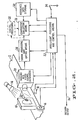
- an object 10 or objects are placed on a moving surface, such as a conveyor belt 12.
- the object is illuminated by an appropriate light source 14.
- the rate of movement of the belt 12 is monitored by a motion detector means, such as a tachometer 16.
- a presence detection means such as an optical marker 18, is positioned so that the movement of the object 10 past a predetermined point along the path of the belt 12 will cause the optical marker 18 to output an object present signal.
- This object present signal and the motion detector means output signal are both supplied to the present invention for use in synchronizing the operation of the present invention with the movement of the belt 12, and the object 10 thereon.
- Means such as a target 11, are provided for optically specifying portions of a properly configured object, or reference object, 13.
- Reference parameter derivation means 15 obtain data from the specified portions of the reference object and derive reference parameters from the data.
- the reference object is optically scanned and converted into electrical image signals by imaging and video circuitry 17.
- the image signals are then supplied to a target recognition circuit 19 which extracts those image signals which correspond to the reference object portions as specified by the targets 11.
- These target image signals are then analyzed in processing circuit 21 to obtain reference parameters which include reference data and an inspection control and processing sequence. These reference parameters are then used by the data processing circuitry 23 in evaluating the particular object under inspection 25.
- imaging and video circuits 27 obtain an equivalent electrical image signal of the object under inspection 25 in accordance with the inspection control and processing sequence.
- the image signal is supplied to image select circuitry 29 where those image signals which correspond to the previously designated portions of the object are selected from the total image signal.
- the selected image signals are compared against the corresponding reference data in comparison circuitry 31.
- Comparison circuitry 31 also evaluates the results of the comparison, in light of the reference parameters, to derive an accept-or-reject decision.
- the imaging and video circuit 17, in the reference parameter derivation circuitry 15, and the imaging and video circuit 27, in the data processing circuitry 23, can be the same physical unit with the timing and control of the circuit differing with the application.
- the target recognition circuit 19 and processing circuit 21, as well as the comparison circuitry 31, can be implemented by a common processing circuit, with a different set of processing steps and criteria being used for the reference parameter derivation mode and for the object inspection mode.
- the reference parameter derivation, or "training” mode and the object inspection mode are implemented using common circuitry, but with different processing steps and criteria for each mode.
- An image of the illuminated object 10 is obtained by imaging and video signal generating means 20.
- the point in time at which acquisition of the image begins, and the rate of acquisition is controlled by signals supplied from the intelligent processing and control means 22. These control and timing signals are, in part, a function of the optical marker 18 signal, and the tachometer 16 signal.
- the image of the object 10 is converted into an equivalent video image signal by the imaging and video signal generator 20, and then supplied to the signal processing and gating means 24.
- the signal processing and gating means provide analog processing, digital processing, as well as a signal selection function.
- the video image signal received from the imaging and video signal generating means 20 is normally in analog form.
- the analog processing includes gain control, buffering and filtering functions. These functions, are controlled by signals supplied from the intelligent processing and control means 22.
- the digital processing functions include analog-to-digital (A/D) conversion, which is also controlled by the intelligent processing and control means 22.
- a gating function is also implemented within the signal processing and gating means 24, under control the intelligent processing and control means, to select certain portions of the image signal and to reject other portions. In this manner, the large quantity of data originally received from the imaging and video signal generating means 20 is greatly reduced in size before being supplied to the comparative evaluation means 26.
- the output of the signal processing and gating means could be routed through a digital processing means 28, shown as a dotted block in Figure 2, before being supplied to the comparative evaluation means 26.
- the gated signals are compared against reference data received from reference data storage means 30.
- the timing by which the reference data are supplied, hence the timing of the comparison operation within the comparative evaluation means 26, is controlled by the intelligent processing and control means 22.
- the results of the comparison operation are supplied to the intelligent processing means 22 which evaluate the data and supply a decision output to the operator.
- the reference data within reference data storage means 30 and the control and timing signal supplied to the various processing blocks by the intelligent processing and control means 22 are derived from information obtained during a "training" phase of the operation of the present invention.
- a reference object is first selected. This reference object serves as a standard of comparison against which the objects to be inspected are compared.
- the reference object could be, for example, a bottle upon which a label is properly oriented, or a box having the proper printing in the proper orientation.
- Optical specifying means are then associated with this reference object and designate a number of reference object portions or features. These features can be label edges, reflectance transitions, or the like.
- the optical specifying means also provide data, including information about the nature of the reference feature being designated, tolerance, and other data, all of which can be optically read by the system.
- the optical specifying means take the form of targets 32, to be described in greater detail later.
- the "training" mode is initiated by the user through switch 34.
- the intelligent processing and control means 22 supply timing and control signals to the various signal processing and conditioning blocks so that the incoming imaging signal can be scanned for the presence of targets 32.
- the intelligent processing and control means 22 calculate the location of the target, more specifically, the nominal location of the reference feature designated by such target. Additionally, the intelligent processing and control means 22 process the reference feature specifications which are also supplied by the target 32.
- the intelligent processing and control means 22 perform this step for all targets found on the reference object being scanned.
- the system is prepared to examine image signals from an object under inspection, which correspond to certain specified nominal locations or portions on the object, for certain specified characteristics.
- the specified characteristics are held in reference data storage means 30, and the specified location determines the timing control signals supplied to the imaging and video signal generating means 20 and the signal processing and gating means 24 during actual object inspection.
- the output of the comparative evaluation means 26 is examined by the intelligent processing and control means 22, in accordance with the reference parameters obtained in the "training" step, to determine whether, for example, any differences between the inspected object and the reference object are within tolerance. The results of this decision are output to the user on decision output line 36.
- the apparatus can be configured for a "training" mode in which reference parameters are obtained by scanning a properly configured object upon which targets are placed to specify certain reference features.
- the apparatus is then reconfigured for an inspection mode, according to the reference parameters obtained in "training" mode, to analyze certain segments of the image signal of the object under inspection, the reference parameters dictating the segments which are selected, the characteristics to be analyzed, and the criteria to be used.
- the imaging and video signal-generating means 20 include an imaging lens 38, an array 40 for transforming the optical image from the imaging lens 38 into an equivalent electronic signal, and a video conditioner 42.
- the imaging lens 38 focuses the image on the array.
- the array is then scanned according to timing and control signals supplied from the intelligent processing and control means 22, on line 44.
- the intelligent processing and control means 22 is microprocessor based, and includes a slave microprocessor 46 and a host microprocessor 48.
- the slave microprocessor 46 handles the actual generation of timing and control signals which are supplied to the various signal processing blocks, while the host microprocessor 48 supplies the instructions by which the slave microprocessor 46 forms the timing and control signals.
- the slave microprocessor 46 also evaluates the results of the comparison function in comparative evaluation means 26 and supplies these results to the host microprocessor 48.
- the host microprocessor 48 makes the final decision as to whether to accept or reject the object being inspected.
- the slave microprocessor 46 In the "training" mode the slave microprocessor 46 is instructed by the host microprocessor 48 to recognize the "training" targets 32 and to recover information provided therein. The host microprocessor 48 then utilizes this information to determine the particular instruction set to be supplied to the slave microprocessor 46 by which the timing and control and data evaluation are to be performed during the object inspection mode. The interaction of the slave microprocessor 46 and host microprocessor 48 will be described in greater detail later.
- the video image signal from video conditioner 42 is supplied to the signal processing and gating means 24.
- the signal processing and gating means 24 include a video receiver and an analog-to-digital (A/D) converter.
- the video receiver 60 buffers and conditions the video image signal from the video conditioner 42.
- the video receiver 60 can be configured to accept an automatic gain control (AGC) signal, analog offset signals, and the like from the slave microprocessor 46. Additionally, the video receiver 60 can be operated in a differential, an integral, or a single-ended input mode.
- AGC automatic gain control
- Other forms of signal enhancement which can be implemented at this point include scan line to scan line correlation, element to element correlation along the orthogonal axis, subtraction of the reference from unknown signals and similar analog arithmetic operations. These can generally be implemented using adding and substracting amplifiers in combination with tapped delay lines.
- the output from video receiver 60 is supplied to A/ D converter 62.
- the A/D converter 62 can be designed to operate over a wide range of conversion speeds -for example, one conversion per second to ten thousand conversions per second. Also, the range of the converter 62 can be selected for resolutions as low as two bits (equivalent to a two level comparator) to as high as 18 bits, for example. The larger the number of bits, the larger the number of resolved signals into which the incoming analog image signal can be separated. Additionally, the A/D converter 62 can operate with a floating or a fixed full scale value; i.e., the input image signal voltage, for which the digital output of the A/D converter is the maximum available for the converter, can be either provided from some variable source or by reference voltage.
- the reference voltage can be generated by analog signals corresponding to, for example, the reflectance of an optical target in the field of the view of the system, the illumination of the source, or some other varying target or signal related reference voltage. This feature is useful, for example, in compensating for the change in ambient light at an inspection station during the workday. In the latter case, the digital output of the A/D converter 62 is not adjusted for variations in signal characteristics, and the reference voltage remains fixed.
- the A/D converter 62 can have an additional variable property, that of suppressing or elevating the converter zero; that is, a zero digital signal can be generated for a nonzero image signal input.
- a reference signal is generated either using signal-related voltages, similar to the example given above for full scale adjustment, by supplying fixed voltages; by a digital-to-analog converter operating under intelligent processing and control means control; or reflectance data from a target.
- timing by which the A/D converter 62 digitizes the image signal supplied from video receiver 60 is governed by timing or enable signals supplied from the slave microprocessor 46 on line 64.
- This enable signal provides the gating control by which only selected portions of the video image signal are permitted to pass for further processing.
- the signal at the output of signal processing and control means 24 can be subjected to further digital processing in digital processing means 28, dotted lines. Operations such as digital correlation, delay, subtraction or other arithmetic processes can be implemented here.
- the signal emerging from signal processing and gating means 24 is supplied directly to comparative evaluation means 26.
- the comparative evaluation means includes a voltage comparator which determines whether the signal supplied by the signal processing and gating means is greater than the corresponding reference data from the reference signal storage means 30.
- One simplified example of the above comparison operation and of the analysis of the results of the operation by the intelligent processing and control means 22 could involve a reference feature having a horizontal, high-to-low reflectance transition along a horizontal point Y 0 , and a tolerance specification of + 1 ⁇ 8 inch. Assume for this example that each vertical scan covers 1/16 inch.
- Possible reference data which would be stored in reference data storage 30 include high level data for all position coordinate pairs above Y , and low level data below Y 0 . Assume that the image data from the object under test turned out to be high levels for all position coordinate pairs above Y + and low levels for all position coordinate pairs below Y + .
- FIG. 3 An additional block is shown in Figure 3, that of an A/D data storage means 66. This permits the digitized image signal being supplied to the comparative evaluation means 26 to be simultaneously stored in memory for evaluation at a later date. In this manner, a preliminary evaluation can be made through comparator 26, while a later, more detailed evaluation can be made using data stored within A/D data storage means 66.
- the intelligent processing and control means 22 includes a slave microprocessor 46, a read only memory (ROM) for nonvolatile program memory 52, a first random access memory (RAM) memory 54 for receiving slave microprocessor instructions from a host microprocessor 48, timing control means 50 which can be programmed by the slave microprocessor to control the imaging and video signal generator means 20, second RAM memory 56, and third RAM memory 58, for temporary data storage.
- ROM read only memory
- RAM random access memory
- ROM memory 52 is provided so that the system will have a defined power-on or initialization condition.
- the slave microprocessor 46 accesses the ROM 52 for its instructions.
- the slave microprocessor 46 reads instructions contained in first RAM memory 54. These instructions, which have been previously loaded into RAM 54 by the host microprocessor 48, dictate timing and the sequence of the operations to be performed by slave microprocessor 46. These instructions can direct the slave microprocessor 46 in the recognition and evaluation of target image signals. They can also instruct the slave microprocessor 46 in the control of the processing circuits to select portions of the image signal from an object being inspected for further processing.
- Typical operations include control of the imaging and video signal means 20, the reading of data stored within the A/D data storage means 66 and the supplying of those values to the host microprocessor 48, and the transfer of reference signal data to the reference data storage means 30 from second RAM memory 56 for use by the comparative evaluation means 26.
- slave microprocessor 46 While the operations of the slave microprocessor 46 are simple in nature, these operations must be performed at high speed and in real time; in other words, at the incoming video image signal rate.
- a typical sequence for the slave microprocessor 46 during the evaluation of an image can consist of the following steps: 1) Read the comparative data from second RAM memory means 56 and output it to the reference data storage means 30; 2) check the results of the comparison in comparative evaluation means 26; 3) store these results in third RAM memory means 58 for access by host microprocessor 48; 4) read the contents of A/D data storage means 66 and put this information in second RAM memory means 56 for future processing; and 5) inform the host microprocessor 48 when processing of the full image has been completed. At this point, the host microprocessor 48 accesses the second RAM memory 56 which holds the results of the comparison operation, and analyzes these results according to some preset criteria.
- the instructions stored in the first RAM memory 54 by the host microprocessor 48 during setup and training can be very different from those required for actual testing. Allocating the processing tasks in this manner allows the imaging and processing and real-time control sections to be very general and yet require only minimal amounts of hardware.
- the functional blocks as shown in Figure 1, that of reference parameter derivation means and data processing means can be implemented by one set of hardware and a change in instructional steps.
- the host microprocessor 48 is free to conduct lengthy evaluations while the slave microprocessor 46 is performing functions on a real time basis.
- the real time functions performed by the slave microprocessor 46 are totally under the control of the host microprocessor 48 and can be altered from time to time depending upon the requirements of the tests being conducted.
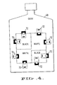
- Figure 4 is an example of the positioning of one embodiment of the optical pre-programming means upon a reference object.
- a bottle 68 having a gray color has a black and white rectangular label 70 positioned thereon.
- targets 72 At various positions on the edge of the label 70, are affixed one embodiment of the target 32, in this case targets 72.
- a typical target 72 is shown in greater detail in Figure 5.
- the optical specifying means designates a nominal location for a particular reference feature on the reference object, information regarding the nature of the reference feature, tolerance information by which the reference feature is to be inspected, and a number of other reference feature specifications.
- Essential to the operation of the optical specifying means is that it be optically distinguishable from patterns normally found in the product or objects to be inspected.
- the edges of the target are lined with spaced apart teeth. The tooth width and the spacing between each tooth is selected to provide an optical pattern which is highly unlike any expected pattern on the object to be inspected.
- the teeth 74 located on perpendicular edges of the target 72 are arranged in different patterns.
- the pattern at the left side of target 72 has a number of equally spaced and equally wide teeth with the exception of a double-width tooth less than halfway down along the edge.
- the identical pattern is implemented on the right side of the target 72.
- the patterns at the top and the bottom of the target are different.
- a wider tooth is positioned at the one-third and two-thirds interval along the edge, with the other teeth being of smaller width.
- a single double-width tooth is positioned at the center point with the other teeth being of smaller width. In this manner, the upper edge and the lower edge can be distinguished from each other.
- the target has a window 76.
- this window is a hole in the target.
- the actual reference feature of the reference object can be scanned.
- the upper portion 78 of the target has low-reflectance, while the lower portion 80 of the target has high reflectance.
- the transition between dark and light occurs at a point midway along the left and right edge of the window 76.
- a short, high-reflectance strip is positioned at a point midway along the top edge of the window 76, while a short, low-reflectance strip is positioned at a point midway along the bottom edge of the window. In this manner, these light and dark strips along with the dark-to-light transition create a kind of cross hair or graticule by which the nominal position of the reference feature is designated.
- a wide, low-reflectance strip is located thereon. This strip provides tolerance information to the system and can be selected by the operator.
- the training target accomplishes, by optical means, the following tasks:
- the target is recognized as such by the system in the following manner.
- the imaging and video signal generator 20 or scanner comprises a vertical scanning diode array which generates a vertical raster scan across the target. This results in the analog electrical signal shown at the bottom of Figure 5.
- the higher signal level regions correspond to white or light color in the image, while the low signal level regions correspond to dark or black areas.
- Scan 1 is the signal generated before the target is encountered. When a target is positioned on a label, this scan will probably include regions corresponding to the structure associated with the label contents, container surface, or other features. Recall that the patterns selected for target recognition are selected to be as different as possible from any anticipated real target pattern.
- Scan 2 is the pattern generated when the scanning array first encounters the pattern edge of the target.
- the object being inspected is being moved across the field of view of the scanner by the moving platform 12.
- the image therefore, sweeps across the vertical scanning array in a direction opposite that of the actual movement of the object. Consequently, each vertical scan produced by the scanning array results in an electrical signal which is slightly displaced from the previous line.
- Scan 3 although displaced from Scan 2, generates the identical signal over the edge pattern. This is because the pattern is constructed to extend over a significant horizontal distance.
- This electrical signal pattern will be recognized by the intelligent processing and control means 22 as a target signal.
- the particular pattern generated informs the intelligent processing and control means 22 of the orientation of the target.
- the system can automatically calibrate its dimensional calculations for magnification due to the imaging means for distortions due to optical and geometric effects within the imaging and video signal generator. Once this is done, the system can then measure fixed dimensions in the object plane occupied by the target.
- the edge pattern also serves to indicate to the system the location of the center of the window.
- the black and white background coloration of the target provides additional confirmation to the system of the location of the center of the window, in addition to assisting the operator in aligning the reference feature with the center of the window.
- the target when the target is affixed to the reference object, and over the reference feature, the target is oriented to include the darker side of the reference feature in the portion of the window corresponding to the dark background. This ensures that the system knows the direction and orientation of the high-to-low transition and where the transition occurs.
- the system can independently identify the position of the window by monitoring the target edge patterns. Using the edge patterns as gating controls, the system stores the digitized form of the analog reflectance signal from the label and bottle surface within the window, and uses this information as the reference data corresponding to the particular object.
- the system does not record any signals from the targets themselves (except for X/Y location of the information within the windows) or from areas of the target not enclosed by the window of the training target.
- the X/Y location information is referenced to the point on the object at which the system first began the scanning operation.
- a system stores actual reflectance data corresponding to the critical features of the reference object, and obtains information on the nature and orientation of the feature and its nominal location.
- the black and white strips 77 adjacent to the top and bottom edges of the window 76 are additional aligning aids for the operator, and need not be used.
- the system measures the width of this black strip and uses the width directly to set boundaries around the nominal location of the feature in the window. Because the system has already automatically calibrated itself to measure dimensions in the plane of the target, it can compute the physical tolerance in absolute units for future display.
- FIG. 6 another embodiment of the optical pre-programming means is illustrated.
- This embodiment is a circularly symmetric target 82.
- the center of the target can be a hole or made up of a transparent material.
- a half-black and half-white ring 84 is located concentrically with the window 81.
- Other larger diameter concentric rings 83 are positioned about the window.
- Located towards the outer edge of the target are radially extending bars 85.
- the radial pattern ensures that the target generates the same type of signature when encountered and scanned by the inspection system, irrespective of its orientation.
- the resulting equivalent electrical signals will vary in frequency according to the graph shown in Figure 7.
- Line A in Figure 7 corresponds to the vertical scan resulting from the outermost scan of the target, while lines F correspond to the vertical scan representing the equivalent video signal resulting when scanning includes the concentric circle area of the target.
- the radial bars 85 of the target are narrow and long, thereby minimizing the effects of the phase of the target frequency, and providing as large a number of recognition scans as possible.
- the scaling of the signature can be obtained in two ways. First, with larger labels, larger targets will be used, thereby keeping the ratio of field height to target height reasonably controlled. Second, the recognition routine used to identify the particular signal will be in the frequency domain and will be implemented, in part, by control of the signal processing and gating circuit 24. The relative shape, in frequency space, rather than being restricted to a particular unique frequency can then be examined for recognition purposes.
- the target 82 is approximately located in the field of view by means of an extrapolation of the initial time-bar geometry. This requires that the signal processing circuitry 24 be switched from the frequency transform mode required in recognition to the spatial analysis mode required for geometrical positioning.
- the system will encounter, sooner or later, one of the black sections which are located at the inner edge of the radial-bar region.
- the system will encounter at least two of these before scanning across the clear area of the target window.
- These black sections 87 prenotify the system of the orientation of the cross hairs and the black/white section of the innermost concentric ring, thereby simplifying the problems of recognizing the light/dark separation and the location of the target center.
- the concentric ring area is included in the target to enable additional information to be encoded in the ring width.
- This additional information can be tolerance data, grade level, threshold information, or other parameter data, and will be read into the apparatus.
- An alternative embodiment of the circular target is to omit the concentric ring area, which can be done when additional information is not required.
- the radial bar area can then be extended further in toward the center of the target, thereby providing a large amount of varying horizontal structure close to the center of the target. With such a configuration, the center of the target is more easily located.
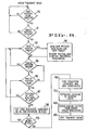
- Figure 10 illustrates the "training" mode of the present invention.
- the system enters the "training" mode illustrated in Figure 8, and the system begins scanning a reference object.
- the target configuration in Figure 5 is being scanned.
- steps 90 and 91 the system loops through each vertical scan until a target is detected. Note that the data from the current scan are examined after the scan is complete, rather than simultaneously with the scan. This permits the system to scan rapidly until an area having a target is encountered, thus speeding the scanning process. Recall that the edge patterns of a target extend for a distance covering several vertical scan widths. The system can, therefore, rapidly scan for the presence of a target, and, upon detection of a target, switch to a slower scan speed for actual data gathering, with a substantial portion of the edge pattern still being available for scanning.
- step 93 determines whether it is a new target and, if so, opens a new data block and records location information for the new target, step 94. The system will thereafter continue to monitor the current vertical scan for new targets until the scan is complete, steps 95 and 96.
- step 97 examines the target scan patterns obtained for differences from the target patterns obtained in the previous scan.
- a difference in target pattern indicates a non-recurring block of data, i.e. that the scan has entered a new portion of the target, the location of which is recorded in step 98. If no differences are detected in step 97 the system continues to process the vertical scans, recording locations of non-recurring blocks of data, until the reference object leaves the field of view (F.O.V.) of the system, step 99.
- step 100 is processed in which all transition locations are found and saved.
- step 102 the location of the window limits are calculated and saved. This computation is based upon the edge patterns of the target which have been detected, and the internal reflectance data of the target, all referenced to the point at which the apparatus began scanning the reference object.
- step 104 the intelligent processing and control means 22 compare the dimensional data obtained in step 102 to a previously specified nominal dimension for the type of target being used. From this comparison, the apparatus can derive a scaling factor for magnification compensation. In this manner, the intelligent processing and control means 22 can examine the tolerance bar to determine the required tolerance range by which the window for viewing the objects to be inspected can be varied. After the scaling factor is obtained in step 104, the intelligent processing and control means 22 proceeds to step 106 in which it exists from the "training" mode.
- the apparatus In the "training" mode, the apparatus, therefore, views a reference object and detects the presence of "training” targets. From these "training" targets, the apparatus obtains window location data, window tolerance data, reflectance transition information, and calculates scaling factors.
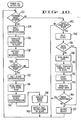
- the slave microprocessor 46 performs a predetermined and prespecified sequence of steps, with the host microprocessor specifying the substeps within certain of these steps. Whether the apparatus is in a "training" mode or in an inspection mode, the slave microprocessor 46 executes the following sequence of steps.
- step 110 the slave microprocessor 46 loops until an object enters the field of view of the imaging and video signal generator 20.
- the slave microprocessor 46 in step 112 accesses RAM memory, for example, first RAM memory 54, to retrieve instructions placed there by the host microprocessor 48.
- the slave microprocessor 46 then executes these instructions in processing and gating the image signal being obtained through the processing circuits 20, 24 and 26.
- the slave microprocessor 46 proceeds to step 114 in which it notifies the host microprocessor that the acquired data is ready. This information can be data from the "training" mode or the object inspection mode.
- step 116 the slave microprocessor transfers data to the host microprocessor 48.
- step 118 the slave microprocessor determines whether a new object is within its field of view. If not, the slave microprocessor proceeds to step 110 and waits for a new object. If a new object is within the field of view, after step 116 has been processed, this indicates that the image data obtained may be erroneous. This is because the slave microprocessor is assumed to have completed its processing of image data before the next object to be inspected enters the field of view of the imaging and video signal generator 20. In step 120, this data error is reported to the host microprocessor 48, and the slave microprocessor 48 proceeds to step 112 in which image data is again attempted to be obtained.
- the host microprocessor 48 determines whether a "training" mode or an inspection mode has been requested. If a "training" mode has been requested, the host microprocessor proceeds to step 124 and halts the operation of the slave microprocessor 46. In step 126, the host microprocessor transfers "training" instructions, or reference extraction signals, to the slave microprocessor, for example, by placing the instructions into first RAM memory 54. In step 128, the slave microprocessor 46 is restarted and data is acquired as described above; see Figure 9.
- the host processor 48 loops in step 130 until the data from the slave microprocessor 46 is ready.
- the host microprocessor halts the slave micro-processor 46 operation, step 132, and reads the "training" image data from the slave microprocessor RAM, for example, second RAM memory 56 in step 134.
- the slave microprocessor 46 is restarted, step 136. After step 136, the host microprocessor analyzes the image data as illustrated in Figure 8, step 138.
- step 140 the host micro-processor, based upon the analysis of the image data, selects a set of test instructions, or an inspection control and processing sequence, for object inspection, and inserts these test instructions into the slave microprocessor RAM, for example, the first RAM memory 54.
- the host microprocessor proceeds to step 122 and determines whether the apparatus remains in the "training" mode, or whether an object inspection has been requested.
- step 142 determines whether test data from the slave microprocessor 46 is ready. Once the test instructions have been transferred in step 140, the slave microprocessor 46 is capable of performing object inspection. Therefore, if after step 140, an object enters the field of view of the imaging and video generator 20, imaging data will be obtained by the slave microprocessor 46. In step 142, the host microprocessor 48 determines whether such data gathering has occurred and, if so, whether the process has been completed. If the slave microprocessor 46 is still acquiring data, the host microprocessor 48 loops back to step 122.
- the host microprocessor 48 in step 144, halts the slave microprocessor 46 operation.
- the host micro-processor 48 determines whether a data error has occurred during the acquisition of the image data, step 146. If such error has occurred, the host microprocessor 48 proceeds to step 148 in which a rejection is reported to the operator. When a reject is reported in step 148, the host microprocessor 48 returns to step 122 and begins the procedure anew. If in step 146 no data error arose, the host microprocessor proceeds to read the image data stored in RAM, for example second RAM memory 56, step 148. In step 150, the host microprocessor 48 signals the slave microprocessor 46 that the data transfer has been completed.
- step 152 the host microprocessor 48 restarts the operation of the slave microprocessor 46.
- step 154 the host microprocessor 48 analyzes the image data just obtained and, in step 156, determines whether according to the "training" image data and analysis, the image is acceptable. If so, the host microprocessor 48 proceeds to step 122 and begins the process for the next object. If the image is unacceptable, the host microprocessor proceeds to step 148 and reports a reject.
- a slave and a host microprocessor are utilized.
- the host microprocessor executes most of the decision-making steps in the process, while the slave microprocessor handles the control and data acquisition steps.
- the slave microprocessor looks to the host microprocessor for instructions in image data gathering, while the host microprocessor looks to the slave microprocessor for supplying image data which is to be analyzed.
- the host microprocessor can instruct the slave microprocessor in data gathering under a wide range of conditions.
- the instructions supplied by the host microprocessor to the slave microprocessor can be instructions for directing the slave microprocessor in acquiring data for a "training" mode, or for acquiring data from objects to be inspected.
- the slave micro- processor supplies the actual processing and control signals to the various signal-processing circuits, for example, the imaging and video generator 20, the signal processing and gating means 24, and the comparative evaluation means 26. These processing and control signals, however, are formed by the slave micro- processor according to instructions supplied by the host microprocessor.
- the above identified apparatus implements a method for automatic optical inspection of specified item.
- the method employs a technique of obtaining a large number of image data, and eliminating redundant, unimportant, and extraneous portions of such data so that the data upon which a decision is to be made is small in quantity. This permits higher processing speed, the ability to perform signal enhancement techniques on such data in real time, and a reduction in the amount of circuitry required for such processing.
- the method includes the steps of providing the system with reference image data through the use of "training" targets. These "training" targets are placed upon a reference object and designate features of the reference object to be examined, and supplying location, tolerance, and other information about the reference features.
- the method includes the steps of obtaining an equivalent electrical image signal of the object under inspection, and processing and gating this image signal according to information obtained in the "training" mode. Following the gating and signal processing step, this image data is compared against reference signal data which was obtained in the "training" mode. The results of the comparison are then evaluated by an intelligent processing and control means which, in turn, renders a decision of acceptance or rejection of the particular object under inspection.
Landscapes
- Physics & Mathematics (AREA)
- General Physics & Mathematics (AREA)
- Engineering & Computer Science (AREA)
- Theoretical Computer Science (AREA)
- Investigating Materials By The Use Of Optical Means Adapted For Particular Applications (AREA)
- Image Analysis (AREA)
- Image Processing (AREA)
- Length Measuring Devices By Optical Means (AREA)
Applications Claiming Priority (2)
| Application Number | Priority Date | Filing Date | Title |
|---|---|---|---|
| US06/273,508 US4509075A (en) | 1981-06-15 | 1981-06-15 | Automatic optical inspection apparatus |
| US273508 | 1999-03-22 |
Publications (2)
| Publication Number | Publication Date |
|---|---|
| EP0067438A2 true EP0067438A2 (fr) | 1982-12-22 |
| EP0067438A3 EP0067438A3 (fr) | 1983-12-28 |
Family
ID=23044224
Family Applications (1)
| Application Number | Title | Priority Date | Filing Date |
|---|---|---|---|
| EP82105185A Withdrawn EP0067438A3 (fr) | 1981-06-15 | 1982-06-14 | Appareil automatique d'inspection optique |
Country Status (3)
| Country | Link |
|---|---|
| US (1) | US4509075A (fr) |
| EP (1) | EP0067438A3 (fr) |
| JP (1) | JPS582980A (fr) |
Cited By (11)
| Publication number | Priority date | Publication date | Assignee | Title |
|---|---|---|---|---|
| GB2135447A (en) * | 1983-02-22 | 1984-08-30 | Metal Closures Ltd | Inspecting screw cap bottle closures |
| FR2600442A1 (fr) * | 1986-06-23 | 1987-12-24 | Gen Electric | Procede de reconstruction d'objets a partir de balayages a angle limite dans une tomographie informatisee |
| WO1988000862A1 (fr) * | 1986-08-04 | 1988-02-11 | The Coca-Cola Company | Procedes pour differencier des recipients contamines de recipients non contamines |
| EP0300545A1 (fr) * | 1987-07-09 | 1989-01-25 | Industrial Contractors Holland B.V. | Appareil pour l'identification d'une ou de plusieurs objets en forme de feuille, par exemple un magazine, procédé d'identification et dispositif de reconnaissance |
| US4858768A (en) * | 1986-08-04 | 1989-08-22 | The Coca-Cola Company | Method for discrimination between contaminated and uncontaminated containers |
| EP0375157A3 (fr) * | 1988-11-28 | 1990-10-17 | Intertest Ltd. | Système d'examen à rayons X "on-line" |
| US4998824A (en) * | 1988-04-13 | 1991-03-12 | International Integrated Systems, Inc. | System of fluid inspection and/or identification |
| US5002397A (en) * | 1988-04-13 | 1991-03-26 | International Integrated Systems, Inc. | System of fluid inspection and/or identification |
| GB2248934A (en) * | 1990-09-17 | 1992-04-22 | Fmc Corp | Automatic windowing for article recognition |
| US5353358A (en) * | 1990-09-24 | 1994-10-04 | Fmc Corporation | Method for determining article orientation in an article handling system using a sampling of a CCD array |
| FR2775204A1 (fr) * | 1998-02-25 | 1999-08-27 | Pellenc Sa | Procede et installation de tri de fruits et legumes, permettant la mesure d'au moins une de leurs caracteristiques |
Families Citing this family (44)
| Publication number | Priority date | Publication date | Assignee | Title |
|---|---|---|---|---|
| GB8300512D0 (en) * | 1983-01-10 | 1983-02-09 | Cruickshank J S | Profile imaging techniques |
| US4733360A (en) * | 1984-06-14 | 1988-03-22 | Dai Nippon Insatsu Kabushiki Kaisha | Device and method for inspecting card-like articles |
| US4697245A (en) * | 1984-11-29 | 1987-09-29 | Cbit Corporation | Inspection and measuring apparatus and method |
| JPH07114180B2 (ja) * | 1985-11-25 | 1995-12-06 | 富士通株式会社 | 半導体露光パタンデータ検査方法及び検査装置 |
| US4751386A (en) * | 1987-03-31 | 1988-06-14 | Emhart Industries, Inc. | Lean detector for determining the offset of an axis of symmetry of a container from its norm |
| GB8724527D0 (en) * | 1987-10-20 | 1987-11-25 | Cruickshank J S | Projection apparatus |
| US4972494A (en) * | 1988-02-26 | 1990-11-20 | R. J. Reynolds Tobacco Company | Package inspection system |
| US4931632A (en) * | 1988-10-07 | 1990-06-05 | Brandt Manufacturing Systems, Inc. | Variable parameter optical bottle checker |
| US5115475A (en) * | 1990-06-04 | 1992-05-19 | Motorola, Inc. | Automatic semiconductor package inspection method |
| US5257325A (en) * | 1991-12-11 | 1993-10-26 | International Business Machines Corporation | Electronic parallel raster dual image registration device |
| US6014461A (en) * | 1994-11-30 | 2000-01-11 | Texas Instruments Incorporated | Apparatus and method for automatic knowlege-based object identification |
| JP3099666B2 (ja) * | 1995-02-16 | 2000-10-16 | 株式会社デンソー | 物品検査装置 |
| JPH09222312A (ja) * | 1996-02-16 | 1997-08-26 | Mitsui Mining & Smelting Co Ltd | パターン検査装置および方法 |
| US6091846A (en) * | 1996-05-31 | 2000-07-18 | Texas Instruments Incorporated | Method and system for anomaly detection |
| US6292582B1 (en) | 1996-05-31 | 2001-09-18 | Lin Youling | Method and system for identifying defects in a semiconductor |
| US6205239B1 (en) | 1996-05-31 | 2001-03-20 | Texas Instruments Incorporated | System and method for circuit repair |
| US6246787B1 (en) | 1996-05-31 | 2001-06-12 | Texas Instruments Incorporated | System and method for knowledgebase generation and management |
| US6046462A (en) * | 1997-12-16 | 2000-04-04 | Eastman Kodak Company | Method and apparatus for determining orientation of parts resting on a flat surface |
| US5955740A (en) * | 1997-12-16 | 1999-09-21 | Eastman Kodak Company | Inspection method and apparatus for determining the side-up orientation of an object resting on a flat surface |
| US6131817A (en) * | 1998-10-09 | 2000-10-17 | Nbs Technologies, Inc. | Plastic card transport apparatus and inspection system |
| US6734981B1 (en) | 2000-11-28 | 2004-05-11 | Honeywell International Inc. | Multiple laser optical systems and methods |
| US6787756B2 (en) * | 2001-04-12 | 2004-09-07 | Honeywell International Inc. | Semiconductor laser-based area scanner |
| US6875993B2 (en) | 2001-04-12 | 2005-04-05 | Honeywell International Inc. | Systems and methods for optically detecting and identifying objects in an environment |
| US6817528B2 (en) * | 2001-07-17 | 2004-11-16 | Honeywell International Inc. | Reflective apparatus and method for optically sensing relative torque employing Moirè fringes |
| US20030015591A1 (en) * | 2001-07-17 | 2003-01-23 | Chen Bo Su | Transmissive apparatus and method for optically sensing relative torque employing moire fringes |
| JP2004198265A (ja) * | 2002-12-18 | 2004-07-15 | Dainippon Printing Co Ltd | 加工製品の外観検査、選別方法および加工製品の外観検査、選別システム |
| US7010863B1 (en) | 2004-01-26 | 2006-03-14 | Owens-Brockway Glass Container Inc. | Optical inspection apparatus and method for inspecting container lean |
| KR100612691B1 (ko) * | 2004-04-30 | 2006-08-16 | 에스케이 텔레콤주식회사 | 동영상 화질 평가시스템 및 방법 |
| US7991242B2 (en) | 2005-05-11 | 2011-08-02 | Optosecurity Inc. | Apparatus, method and system for screening receptacles and persons, having image distortion correction functionality |
| US20070041613A1 (en) * | 2005-05-11 | 2007-02-22 | Luc Perron | Database of target objects suitable for use in screening receptacles or people and method and apparatus for generating same |
| CA2608119A1 (fr) | 2005-05-11 | 2006-11-16 | Optosecurity Inc. | Procede et systeme d'inspection de bagages, de conteneurs de fret ou de personnes |
| US7899232B2 (en) | 2006-05-11 | 2011-03-01 | Optosecurity Inc. | Method and apparatus for providing threat image projection (TIP) in a luggage screening system, and luggage screening system implementing same |
| US8494210B2 (en) | 2007-03-30 | 2013-07-23 | Optosecurity Inc. | User interface for use in security screening providing image enhancement capabilities and apparatus for implementing same |
| US8824731B2 (en) * | 2007-10-31 | 2014-09-02 | The Boeing Comapny | Image processing of apparatus condition |
| JP5490627B2 (ja) * | 2010-06-17 | 2014-05-14 | 株式会社ミツトヨ | 画像機器の校正用パターン |
| US9560808B2 (en) * | 2011-04-19 | 2017-02-07 | Cnh Industrial America Llc | System for controlling bale forming and wrapping operations |
| US9111331B2 (en) | 2011-09-07 | 2015-08-18 | Rapiscan Systems, Inc. | X-ray inspection system that integrates manifest data with imaging/detection processing |
| US20130265410A1 (en) * | 2012-04-10 | 2013-10-10 | Mahle Powertrain, Llc | Color vision inspection system and method of inspecting a vehicle |
| US9759553B2 (en) * | 2013-07-09 | 2017-09-12 | Auburn University | Determining geometric characteristics of reflective surfaces |
| US20150051860A1 (en) * | 2013-08-19 | 2015-02-19 | Taiwan Semiconductor Manufacturing Co., Ltd. | Automatic optical appearance inspection by line scan apparatus |
| US9558547B2 (en) * | 2014-01-09 | 2017-01-31 | The Boeing Company | System and method for determining whether an apparatus or an assembly process is acceptable |
| JP6528665B2 (ja) * | 2015-12-08 | 2019-06-12 | 株式会社島津製作所 | サンプル識別方法、及び、サンプル識別装置 |
| CN116309260A (zh) | 2016-02-22 | 2023-06-23 | 拉皮斯坎系统股份有限公司 | 用于评估货物的平均货盘尺寸和密度的方法 |
| JP7054436B2 (ja) * | 2017-12-14 | 2022-04-14 | オムロン株式会社 | 検出システム、情報処理装置、評価方法及びプログラム |
Family Cites Families (16)
| Publication number | Priority date | Publication date | Assignee | Title |
|---|---|---|---|---|
| US3662181A (en) * | 1970-04-22 | 1972-05-09 | American Cyanamid Co | Scanning apparatus for the detection and identification of luminescing code bars on articles |
| US3650397A (en) * | 1970-11-19 | 1972-03-21 | Sensors Inc | System for inspecting and classifying objects such as screws, bolts and the like while in motion |
| GB1398720A (en) * | 1971-11-16 | 1975-06-25 | Lucas Electrical Co Ltd | Shape recognition systems |
| US3891324A (en) * | 1972-05-01 | 1975-06-24 | Oliver Machinery Co | Method and apparatus for inspecting position of labels on product surfaces |
| NL7409850A (nl) * | 1974-07-22 | 1976-01-26 | Philips Nv | Werkwijze en inrichting voor het testen van een tweedimensionaal patroon. |
| US4002823A (en) * | 1974-11-01 | 1977-01-11 | Ball Corporation | Method and apparatus for video inspection of articles of manufacture |
| DE2514930A1 (de) * | 1975-04-05 | 1976-10-14 | Opto Produkte Ag | Verfahren zur optischen ermittlung und zum vergleich von formen und lagen von objekten |
| US4037971A (en) * | 1975-06-30 | 1977-07-26 | International Business Machines Corporation | Inspection tool |
| US4065212A (en) * | 1975-06-30 | 1977-12-27 | International Business Machines Corporation | Inspection tool |
| US4079416A (en) * | 1975-12-01 | 1978-03-14 | Barry-Wehmiller Company | Electronic image analyzing method and apparatus |
| GB1573142A (en) * | 1976-01-23 | 1980-08-13 | Hitachi Ltd | Apparatus and method for providing information relating to shape and/or position of an object |
| DE2638138C3 (de) * | 1976-08-25 | 1979-05-03 | Kloeckner-Werke Ag, 4100 Duisburg | Vorrichtung zum Erkennen und Aussortieren fehlerhafter Packungen, die längs einer Förderstrecke transportiert werden |
| US4115939A (en) * | 1976-10-04 | 1978-09-26 | Cedric Marks | Bottle with a multiple part label |
| JPS54140838A (en) * | 1978-04-20 | 1979-11-01 | Honeywell Inc | Article identifier |
| US4229797A (en) * | 1978-09-06 | 1980-10-21 | National Biomedical Research Foundation | Method and system for whole picture image processing |
| US4380025A (en) * | 1979-08-06 | 1983-04-12 | Ball Corporation | Auxiliary blanking and auxiliary simulated video line generator unit for a video inspection system |
-
1981
- 1981-06-15 US US06/273,508 patent/US4509075A/en not_active Expired - Fee Related
-
1982
- 1982-06-14 EP EP82105185A patent/EP0067438A3/fr not_active Withdrawn
- 1982-06-15 JP JP57102951A patent/JPS582980A/ja active Pending
Cited By (14)
| Publication number | Priority date | Publication date | Assignee | Title |
|---|---|---|---|---|
| GB2135447A (en) * | 1983-02-22 | 1984-08-30 | Metal Closures Ltd | Inspecting screw cap bottle closures |
| FR2600442A1 (fr) * | 1986-06-23 | 1987-12-24 | Gen Electric | Procede de reconstruction d'objets a partir de balayages a angle limite dans une tomographie informatisee |
| US5067616A (en) * | 1986-08-04 | 1991-11-26 | The Coca-Cola Company | Methods of discriminating between contaminated and uncontaminated containers |
| US4858768A (en) * | 1986-08-04 | 1989-08-22 | The Coca-Cola Company | Method for discrimination between contaminated and uncontaminated containers |
| AU603133B2 (en) * | 1986-08-04 | 1990-11-08 | Coca-Cola Company, The | Methods of discriminating between contaminated and uncontaminated containers |
| WO1988000862A1 (fr) * | 1986-08-04 | 1988-02-11 | The Coca-Cola Company | Procedes pour differencier des recipients contamines de recipients non contamines |
| EP0300545A1 (fr) * | 1987-07-09 | 1989-01-25 | Industrial Contractors Holland B.V. | Appareil pour l'identification d'une ou de plusieurs objets en forme de feuille, par exemple un magazine, procédé d'identification et dispositif de reconnaissance |
| US4998824A (en) * | 1988-04-13 | 1991-03-12 | International Integrated Systems, Inc. | System of fluid inspection and/or identification |
| US5002397A (en) * | 1988-04-13 | 1991-03-26 | International Integrated Systems, Inc. | System of fluid inspection and/or identification |
| EP0375157A3 (fr) * | 1988-11-28 | 1990-10-17 | Intertest Ltd. | Système d'examen à rayons X "on-line" |
| GB2248934A (en) * | 1990-09-17 | 1992-04-22 | Fmc Corp | Automatic windowing for article recognition |
| GB2248934B (en) * | 1990-09-17 | 1994-11-30 | Fmc Corp | Automatic windowing for article recognition |
| US5353358A (en) * | 1990-09-24 | 1994-10-04 | Fmc Corporation | Method for determining article orientation in an article handling system using a sampling of a CCD array |
| FR2775204A1 (fr) * | 1998-02-25 | 1999-08-27 | Pellenc Sa | Procede et installation de tri de fruits et legumes, permettant la mesure d'au moins une de leurs caracteristiques |
Also Published As
| Publication number | Publication date |
|---|---|
| US4509075A (en) | 1985-04-02 |
| EP0067438A3 (fr) | 1983-12-28 |
| JPS582980A (ja) | 1983-01-08 |
Similar Documents
| Publication | Publication Date | Title |
|---|---|---|
| US4509075A (en) | Automatic optical inspection apparatus | |
| CA2976769C (fr) | Procedes reposant sur un modele et appareil pour une classification d'un interferent dans des echantillons | |
| US4876457A (en) | Method and apparatus for differentiating a planar textured surface from a surrounding background | |
| US4974261A (en) | Optical surface inspection method | |
| Noordam et al. | High-speed potato grading and quality inspection based on a color vision system | |
| US5581632A (en) | Method and apparatus for ball bond inspection system | |
| US5703960A (en) | Lumber defect scanning including multi-dimensional pattern recognition | |
| US5859923A (en) | Mark quality inspection apparatus and method | |
| JP3041090B2 (ja) | 外観検査装置 | |
| EP0155789B1 (fr) | Appareil pour contrôler automatiquement des étiquettes imprimées | |
| JPH0782542B2 (ja) | 印字検査方法、印字検査装置および印刷物自動振分けシステム | |
| EP3942520B1 (fr) | Procédé et système de détection de défauts dans des données d'image d'un revêtement cible | |
| CN117237747A (zh) | 基于人工智能的五金件缺陷分类识别方法 | |
| Delwiche et al. | Prune defect detection by line-scan imaging | |
| CN119395039A (zh) | 基于深度学习模型的锯条齿形缺陷的视觉检测系统 | |
| Aleixos et al. | Assessment of citrus fruit quality using a real-time machine vision system | |
| Islam et al. | Image processing techniques for quality inspection of gelatin capsules in pharmaceutical applications | |
| JPH0210461B2 (fr) | ||
| JP2647502B2 (ja) | パターン比較検査方法および装置 | |
| KR20240129991A (ko) | 딥러닝 기반 ai 머신비전 검사장치 | |
| Ahmed Fadzil et al. | LED cosmetic flaw vision inspection system | |
| CN116804637A (zh) | 检查系统、教师数据生成装置、教师数据生成方法及存储介质 | |
| JP4002387B2 (ja) | 農産物の等級判定方法及び等級判定装置 | |
| CN120431084B (zh) | 一种用于加工led编带机轨道的打磨质量检测方法 | |
| CN121437482A (zh) | 一种工业视觉检测系统 |
Legal Events
| Date | Code | Title | Description |
|---|---|---|---|
| PUAI | Public reference made under article 153(3) epc to a published international application that has entered the european phase |
Free format text: ORIGINAL CODE: 0009012 |
|
| 17P | Request for examination filed |
Effective date: 19820614 |
|
| AK | Designated contracting states |
Designated state(s): AT BE CH DE FR GB IT LI LU NL SE |
|
| PUAL | Search report despatched |
Free format text: ORIGINAL CODE: 0009013 |
|
| AK | Designated contracting states |
Designated state(s): AT BE CH DE FR GB IT LI LU NL SE |
|
| STAA | Information on the status of an ep patent application or granted ep patent |
Free format text: STATUS: THE APPLICATION IS DEEMED TO BE WITHDRAWN |
|
| 18D | Application deemed to be withdrawn |
Effective date: 19851029 |
|
| RIN1 | Information on inventor provided before grant (corrected) |
Inventor name: HANEY, JERRY D. Inventor name: SIMMS, JOHN R. |