EP0067521B1 - Procédé pour optimaliser l'efficacité d'un cristal de laser par l'introduction de sites singuliers destinés au dopant - Google Patents
Procédé pour optimaliser l'efficacité d'un cristal de laser par l'introduction de sites singuliers destinés au dopant Download PDFInfo
- Publication number
- EP0067521B1 EP0067521B1 EP82302369A EP82302369A EP0067521B1 EP 0067521 B1 EP0067521 B1 EP 0067521B1 EP 82302369 A EP82302369 A EP 82302369A EP 82302369 A EP82302369 A EP 82302369A EP 0067521 B1 EP0067521 B1 EP 0067521B1
- Authority
- EP
- European Patent Office
- Prior art keywords
- crystal
- dopant
- laser
- ions
- site
- Prior art date
- Legal status (The legal status is an assumption and is not a legal conclusion. Google has not performed a legal analysis and makes no representation as to the accuracy of the status listed.)
- Expired
Links
- 239000013078 crystal Substances 0.000 title claims description 126
- 239000002019 doping agent Substances 0.000 title claims description 53
- 238000000034 method Methods 0.000 title claims description 50
- 230000008569 process Effects 0.000 title claims description 44
- 239000000463 material Substances 0.000 claims description 76
- JNDMLEXHDPKVFC-UHFFFAOYSA-N aluminum;oxygen(2-);yttrium(3+) Chemical compound [O-2].[O-2].[O-2].[Al+3].[Y+3] JNDMLEXHDPKVFC-UHFFFAOYSA-N 0.000 claims description 72
- 229910019901 yttrium aluminum garnet Inorganic materials 0.000 claims description 71
- 150000002500 ions Chemical class 0.000 claims description 43
- 150000001450 anions Chemical class 0.000 claims description 37
- 230000007547 defect Effects 0.000 claims description 36
- 229910052779 Neodymium Inorganic materials 0.000 claims description 29
- -1 rare earth ions Chemical class 0.000 claims description 25
- XLYOFNOQVPJJNP-UHFFFAOYSA-N water Substances O XLYOFNOQVPJJNP-UHFFFAOYSA-N 0.000 claims description 24
- 239000012535 impurity Substances 0.000 claims description 23
- QVGXLLKOCUKJST-UHFFFAOYSA-N atomic oxygen Chemical compound [O] QVGXLLKOCUKJST-UHFFFAOYSA-N 0.000 claims description 17
- ZCYVEMRRCGMTRW-UHFFFAOYSA-N 7553-56-2 Chemical compound [I] ZCYVEMRRCGMTRW-UHFFFAOYSA-N 0.000 claims description 16
- 239000011630 iodine Substances 0.000 claims description 14
- 229910052740 iodine Inorganic materials 0.000 claims description 13
- 230000005284 excitation Effects 0.000 claims description 11
- 239000000155 melt Substances 0.000 claims description 11
- 238000010438 heat treatment Methods 0.000 claims description 10
- QEFYFXOXNSNQGX-UHFFFAOYSA-N neodymium atom Chemical compound [Nd] QEFYFXOXNSNQGX-UHFFFAOYSA-N 0.000 claims description 10
- 230000007704 transition Effects 0.000 claims description 10
- 239000000203 mixture Substances 0.000 claims description 9
- 239000012254 powdered material Substances 0.000 claims description 8
- 230000015572 biosynthetic process Effects 0.000 claims description 5
- 239000001301 oxygen Substances 0.000 claims description 5
- 229910052760 oxygen Inorganic materials 0.000 claims description 5
- 239000011521 glass Substances 0.000 claims description 4
- QWVYNEUUYROOSZ-UHFFFAOYSA-N trioxido(oxo)vanadium;yttrium(3+) Chemical compound [Y+3].[O-][V]([O-])([O-])=O QWVYNEUUYROOSZ-UHFFFAOYSA-N 0.000 claims description 4
- BIOOACNPATUQFW-UHFFFAOYSA-N calcium;dioxido(dioxo)molybdenum Chemical compound [Ca+2].[O-][Mo]([O-])(=O)=O BIOOACNPATUQFW-UHFFFAOYSA-N 0.000 claims description 3
- PLDDOISOJJCEMH-UHFFFAOYSA-N neodymium(3+);oxygen(2-) Chemical compound [O-2].[O-2].[O-2].[Nd+3].[Nd+3] PLDDOISOJJCEMH-UHFFFAOYSA-N 0.000 claims description 3
- SIWVEOZUMHYXCS-UHFFFAOYSA-N oxo(oxoyttriooxy)yttrium Chemical compound O=[Y]O[Y]=O SIWVEOZUMHYXCS-UHFFFAOYSA-N 0.000 claims description 3
- 229910052761 rare earth metal Inorganic materials 0.000 claims description 3
- OYPRJOBELJOOCE-UHFFFAOYSA-N Calcium Chemical compound [Ca] OYPRJOBELJOOCE-UHFFFAOYSA-N 0.000 claims description 2
- 229910052791 calcium Inorganic materials 0.000 claims description 2
- 239000011575 calcium Substances 0.000 claims description 2
- 229910001602 chrysoberyl Inorganic materials 0.000 claims description 2
- ZPDRQAVGXHVGTB-UHFFFAOYSA-N gallium;gadolinium(3+);oxygen(2-) Chemical compound [O-2].[O-2].[O-2].[Ga+3].[Gd+3] ZPDRQAVGXHVGTB-UHFFFAOYSA-N 0.000 claims description 2
- 230000008018 melting Effects 0.000 claims description 2
- 238000002844 melting Methods 0.000 claims description 2
- 229910052594 sapphire Inorganic materials 0.000 claims description 2
- 239000010980 sapphire Substances 0.000 claims description 2
- 229910052596 spinel Inorganic materials 0.000 claims description 2
- 239000011029 spinel Substances 0.000 claims description 2
- 229910001428 transition metal ion Inorganic materials 0.000 claims description 2
- PBYZMCDFOULPGH-UHFFFAOYSA-N tungstate Chemical compound [O-][W]([O-])(=O)=O PBYZMCDFOULPGH-UHFFFAOYSA-N 0.000 claims description 2
- TWNQGVIAIRXVLR-UHFFFAOYSA-N oxo(oxoalumanyloxy)alumane Chemical compound O=[Al]O[Al]=O TWNQGVIAIRXVLR-UHFFFAOYSA-N 0.000 claims 2
- 229910004647 CaMoO4 Inorganic materials 0.000 claims 1
- 230000002708 enhancing effect Effects 0.000 claims 1
- 238000009738 saturating Methods 0.000 claims 1
- 239000000843 powder Substances 0.000 description 25
- 238000001228 spectrum Methods 0.000 description 9
- 238000010521 absorption reaction Methods 0.000 description 8
- 238000006243 chemical reaction Methods 0.000 description 8
- 230000005855 radiation Effects 0.000 description 7
- 238000012546 transfer Methods 0.000 description 7
- 230000000694 effects Effects 0.000 description 6
- 238000012360 testing method Methods 0.000 description 6
- PNEYBMLMFCGWSK-UHFFFAOYSA-N aluminium oxide Inorganic materials [O-2].[O-2].[O-2].[Al+3].[Al+3] PNEYBMLMFCGWSK-UHFFFAOYSA-N 0.000 description 5
- 230000008859 change Effects 0.000 description 5
- RZVAJINKPMORJF-UHFFFAOYSA-N Acetaminophen Chemical compound CC(=O)NC1=CC=C(O)C=C1 RZVAJINKPMORJF-UHFFFAOYSA-N 0.000 description 4
- CSCPPACGZOOCGX-UHFFFAOYSA-N Acetone Chemical compound CC(C)=O CSCPPACGZOOCGX-UHFFFAOYSA-N 0.000 description 4
- 239000004480 active ingredient Substances 0.000 description 4
- 238000002189 fluorescence spectrum Methods 0.000 description 4
- VYPSYNLAJGMNEJ-UHFFFAOYSA-N silicon dioxide Inorganic materials O=[Si]=O VYPSYNLAJGMNEJ-UHFFFAOYSA-N 0.000 description 4
- 239000007787 solid Substances 0.000 description 4
- GQPLMRYTRLFLPF-UHFFFAOYSA-N Nitrous Oxide Chemical compound [O-][N+]#N GQPLMRYTRLFLPF-UHFFFAOYSA-N 0.000 description 3
- CBENFWSGALASAD-UHFFFAOYSA-N Ozone Chemical compound [O-][O+]=O CBENFWSGALASAD-UHFFFAOYSA-N 0.000 description 3
- 230000009471 action Effects 0.000 description 3
- 238000013459 approach Methods 0.000 description 3
- 238000005090 crystal field Methods 0.000 description 3
- 238000000695 excitation spectrum Methods 0.000 description 3
- 238000005259 measurement Methods 0.000 description 3
- 239000005297 pyrex Substances 0.000 description 3
- 239000010453 quartz Substances 0.000 description 3
- 238000010791 quenching Methods 0.000 description 3
- 238000004611 spectroscopical analysis Methods 0.000 description 3
- XKRFYHLGVUSROY-UHFFFAOYSA-N Argon Chemical compound [Ar] XKRFYHLGVUSROY-UHFFFAOYSA-N 0.000 description 2
- CURLTUGMZLYLDI-UHFFFAOYSA-N Carbon dioxide Chemical compound O=C=O CURLTUGMZLYLDI-UHFFFAOYSA-N 0.000 description 2
- MYMOFIZGZYHOMD-UHFFFAOYSA-N Dioxygen Chemical compound O=O MYMOFIZGZYHOMD-UHFFFAOYSA-N 0.000 description 2
- 229910052765 Lutetium Inorganic materials 0.000 description 2
- 239000004809 Teflon Substances 0.000 description 2
- 229920006362 Teflon® Polymers 0.000 description 2
- 238000000862 absorption spectrum Methods 0.000 description 2
- 235000011089 carbon dioxide Nutrition 0.000 description 2
- 229910001430 chromium ion Inorganic materials 0.000 description 2
- 238000011109 contamination Methods 0.000 description 2
- 230000001419 dependent effect Effects 0.000 description 2
- 238000005516 engineering process Methods 0.000 description 2
- 239000007789 gas Substances 0.000 description 2
- 239000007788 liquid Substances 0.000 description 2
- OHSVLFRHMCKCQY-UHFFFAOYSA-N lutetium atom Chemical compound [Lu] OHSVLFRHMCKCQY-UHFFFAOYSA-N 0.000 description 2
- 238000004519 manufacturing process Methods 0.000 description 2
- 229910021645 metal ion Inorganic materials 0.000 description 2
- 238000012545 processing Methods 0.000 description 2
- 230000000171 quenching effect Effects 0.000 description 2
- 239000000126 substance Substances 0.000 description 2
- 241000931526 Acer campestre Species 0.000 description 1
- VYZAMTAEIAYCRO-UHFFFAOYSA-N Chromium Chemical compound [Cr] VYZAMTAEIAYCRO-UHFFFAOYSA-N 0.000 description 1
- 238000002231 Czochralski process Methods 0.000 description 1
- 229910019142 PO4 Inorganic materials 0.000 description 1
- 230000003213 activating effect Effects 0.000 description 1
- 230000004913 activation Effects 0.000 description 1
- 229910052782 aluminium Inorganic materials 0.000 description 1
- 230000003466 anti-cipated effect Effects 0.000 description 1
- 229910052786 argon Inorganic materials 0.000 description 1
- 230000008033 biological extinction Effects 0.000 description 1
- 230000005540 biological transmission Effects 0.000 description 1
- BJQHLKABXJIVAM-UHFFFAOYSA-N bis(2-ethylhexyl) phthalate Chemical compound CCCCC(CC)COC(=O)C1=CC=CC=C1C(=O)OCC(CC)CCCC BJQHLKABXJIVAM-UHFFFAOYSA-N 0.000 description 1
- OKOSPWNNXVDXKZ-UHFFFAOYSA-N but-3-enoyl chloride Chemical compound ClC(=O)CC=C OKOSPWNNXVDXKZ-UHFFFAOYSA-N 0.000 description 1
- 229910052804 chromium Inorganic materials 0.000 description 1
- 239000011651 chromium Substances 0.000 description 1
- 239000000470 constituent Substances 0.000 description 1
- 229910052593 corundum Inorganic materials 0.000 description 1
- 230000007423 decrease Effects 0.000 description 1
- 230000003247 decreasing effect Effects 0.000 description 1
- 238000011161 development Methods 0.000 description 1
- 229910001882 dioxygen Inorganic materials 0.000 description 1
- 230000005684 electric field Effects 0.000 description 1
- 230000008014 freezing Effects 0.000 description 1
- 238000007710 freezing Methods 0.000 description 1
- 150000004820 halides Chemical class 0.000 description 1
- 239000001307 helium Substances 0.000 description 1
- 229910052734 helium Inorganic materials 0.000 description 1
- SWQJXJOGLNCZEY-UHFFFAOYSA-N helium atom Chemical compound [He] SWQJXJOGLNCZEY-UHFFFAOYSA-N 0.000 description 1
- 239000001257 hydrogen Substances 0.000 description 1
- 229910052739 hydrogen Inorganic materials 0.000 description 1
- 229910000450 iodine oxide Inorganic materials 0.000 description 1
- 238000004020 luminiscence type Methods 0.000 description 1
- 230000007246 mechanism Effects 0.000 description 1
- 229910044991 metal oxide Inorganic materials 0.000 description 1
- 150000004706 metal oxides Chemical class 0.000 description 1
- 229910001120 nichrome Inorganic materials 0.000 description 1
- 239000001272 nitrous oxide Substances 0.000 description 1
- 230000003287 optical effect Effects 0.000 description 1
- 239000002245 particle Substances 0.000 description 1
- 239000010452 phosphate Substances 0.000 description 1
- 150000002910 rare earth metals Chemical class 0.000 description 1
- 230000035484 reaction time Effects 0.000 description 1
- 230000001105 regulatory effect Effects 0.000 description 1
- 238000012552 review Methods 0.000 description 1
- 239000010979 ruby Substances 0.000 description 1
- 229910001750 ruby Inorganic materials 0.000 description 1
- 238000000094 site-selection spectroscopy Methods 0.000 description 1
- 239000007858 starting material Substances 0.000 description 1
- 229910019655 synthetic inorganic crystalline material Inorganic materials 0.000 description 1
- 238000002849 thermal shift Methods 0.000 description 1
- 150000003568 thioethers Chemical class 0.000 description 1
- 229910001845 yogo sapphire Inorganic materials 0.000 description 1
- 229910052727 yttrium Inorganic materials 0.000 description 1
Images


Classifications
-
- H—ELECTRICITY
- H01—ELECTRIC ELEMENTS
- H01S—DEVICES USING THE PROCESS OF LIGHT AMPLIFICATION BY STIMULATED EMISSION OF RADIATION [LASER] TO AMPLIFY OR GENERATE LIGHT; DEVICES USING STIMULATED EMISSION OF ELECTROMAGNETIC RADIATION IN WAVE RANGES OTHER THAN OPTICAL
- H01S3/00—Lasers, i.e. devices using stimulated emission of electromagnetic radiation in the infrared, visible or ultraviolet wave range
- H01S3/14—Lasers, i.e. devices using stimulated emission of electromagnetic radiation in the infrared, visible or ultraviolet wave range characterised by the material used as the active medium
- H01S3/16—Solid materials
-
- C—CHEMISTRY; METALLURGY
- C30—CRYSTAL GROWTH
- C30B—SINGLE-CRYSTAL GROWTH; UNIDIRECTIONAL SOLIDIFICATION OF EUTECTIC MATERIAL OR UNIDIRECTIONAL DEMIXING OF EUTECTOID MATERIAL; REFINING BY ZONE-MELTING OF MATERIAL; PRODUCTION OF A HOMOGENEOUS POLYCRYSTALLINE MATERIAL WITH DEFINED STRUCTURE; SINGLE CRYSTALS OR HOMOGENEOUS POLYCRYSTALLINE MATERIAL WITH DEFINED STRUCTURE; AFTER-TREATMENT OF SINGLE CRYSTALS OR A HOMOGENEOUS POLYCRYSTALLINE MATERIAL WITH DEFINED STRUCTURE; APPARATUS THEREFOR
- C30B15/00—Single-crystal growth by pulling from a melt, e.g. Czochralski method
-
- C—CHEMISTRY; METALLURGY
- C30—CRYSTAL GROWTH
- C30B—SINGLE-CRYSTAL GROWTH; UNIDIRECTIONAL SOLIDIFICATION OF EUTECTIC MATERIAL OR UNIDIRECTIONAL DEMIXING OF EUTECTOID MATERIAL; REFINING BY ZONE-MELTING OF MATERIAL; PRODUCTION OF A HOMOGENEOUS POLYCRYSTALLINE MATERIAL WITH DEFINED STRUCTURE; SINGLE CRYSTALS OR HOMOGENEOUS POLYCRYSTALLINE MATERIAL WITH DEFINED STRUCTURE; AFTER-TREATMENT OF SINGLE CRYSTALS OR A HOMOGENEOUS POLYCRYSTALLINE MATERIAL WITH DEFINED STRUCTURE; APPARATUS THEREFOR
- C30B29/00—Single crystals or homogeneous polycrystalline material with defined structure characterised by the material or by their shape
- C30B29/10—Inorganic compounds or compositions
- C30B29/16—Oxides
- C30B29/22—Complex oxides
- C30B29/28—Complex oxides with formula A3Me5O12 wherein A is a rare earth metal and Me is Fe, Ga, Sc, Cr, Co or Al, e.g. garnets
-
- C—CHEMISTRY; METALLURGY
- C30—CRYSTAL GROWTH
- C30B—SINGLE-CRYSTAL GROWTH; UNIDIRECTIONAL SOLIDIFICATION OF EUTECTIC MATERIAL OR UNIDIRECTIONAL DEMIXING OF EUTECTOID MATERIAL; REFINING BY ZONE-MELTING OF MATERIAL; PRODUCTION OF A HOMOGENEOUS POLYCRYSTALLINE MATERIAL WITH DEFINED STRUCTURE; SINGLE CRYSTALS OR HOMOGENEOUS POLYCRYSTALLINE MATERIAL WITH DEFINED STRUCTURE; AFTER-TREATMENT OF SINGLE CRYSTALS OR A HOMOGENEOUS POLYCRYSTALLINE MATERIAL WITH DEFINED STRUCTURE; APPARATUS THEREFOR
- C30B31/00—Diffusion or doping processes for single crystals or homogeneous polycrystalline material with defined structure; Apparatus therefor
- C30B31/06—Diffusion or doping processes for single crystals or homogeneous polycrystalline material with defined structure; Apparatus therefor by contacting with diffusion material in the gaseous state
-
- H—ELECTRICITY
- H01—ELECTRIC ELEMENTS
- H01S—DEVICES USING THE PROCESS OF LIGHT AMPLIFICATION BY STIMULATED EMISSION OF RADIATION [LASER] TO AMPLIFY OR GENERATE LIGHT; DEVICES USING STIMULATED EMISSION OF ELECTROMAGNETIC RADIATION IN WAVE RANGES OTHER THAN OPTICAL
- H01S3/00—Lasers, i.e. devices using stimulated emission of electromagnetic radiation in the infrared, visible or ultraviolet wave range
- H01S3/14—Lasers, i.e. devices using stimulated emission of electromagnetic radiation in the infrared, visible or ultraviolet wave range characterised by the material used as the active medium
- H01S3/16—Solid materials
- H01S3/1601—Solid materials characterised by an active (lasing) ion
- H01S3/1603—Solid materials characterised by an active (lasing) ion rare earth
- H01S3/1611—Solid materials characterised by an active (lasing) ion rare earth neodymium
-
- H—ELECTRICITY
- H01—ELECTRIC ELEMENTS
- H01S—DEVICES USING THE PROCESS OF LIGHT AMPLIFICATION BY STIMULATED EMISSION OF RADIATION [LASER] TO AMPLIFY OR GENERATE LIGHT; DEVICES USING STIMULATED EMISSION OF ELECTROMAGNETIC RADIATION IN WAVE RANGES OTHER THAN OPTICAL
- H01S3/00—Lasers, i.e. devices using stimulated emission of electromagnetic radiation in the infrared, visible or ultraviolet wave range
- H01S3/14—Lasers, i.e. devices using stimulated emission of electromagnetic radiation in the infrared, visible or ultraviolet wave range characterised by the material used as the active medium
- H01S3/16—Solid materials
- H01S3/163—Solid materials characterised by a crystal matrix
- H01S3/164—Solid materials characterised by a crystal matrix garnet
- H01S3/1643—YAG
Definitions
- This invention relates generally to the field of laser materials and, more particularly, to a process for maximizing the lasing efficiency of a dopant-containing laser oxide material, such as neodymium-doped yttrium aluminum garnet.
- a dopant-containing laser oxide material such as neodymium-doped yttrium aluminum garnet.
- a laser beam is produced by introducing light into a host material which contains an active ingredient, to raise the atoms of the active ingredient to higher energy levels. Subsequently, a number of these active atoms return to their original energy state, doing so in phase, and produce radiation of the same frequency, thus producing a laser beam.
- the first laser action was produced using chromium as the active ingredient in a ruby host material. Later, lasing action was produced by neodymium contained in a glass host material.
- Nd neodymium
- YAG yttrium aluminum garnet
- Nd:YAG lasers are particularly useful for the application of optical methods to measure distance, such as in range finders and in target designators and target illuminators.
- the lasing efficiency of a Nd:YAG laser crystal can be increased to approximately 85 percent by exposing the doped laser crystal to an atmosphere conducive to the formation of atomic oxygen to allow the atomic oxygen to react with and remove water and water-derived impurities from the laser crystal.
- the doped laser crystal is heated at 1500°C in a vapor mixture of oxygen and iodine having mole concentrations in the ratio of 10:1, to produce the required atomic oxygen to react with and remove the impurities in the laser crystal. While the above-described process provides a laser oxide material which is hightly satisfactory for many applications, the present invention provides still additional new and improved processes for increasing the lasing efficiency of laser oxide materials even further.
- the purpose of the present invention as claimed is to provide new and improved processes as claimed in independent claims 1, 2, 6 and 11 for maximizing the lasing efficiency of dopant-containing laser oxide materials, and the improved lasing materials formed by such processes, and as claimed in independant claims 7 and 10.
- a dopant-containing laser oxide material is provided in the form of a powder.
- the powdered material is placed in a crystal growth chamber adapted for crystal growth from a melt, and the powder is heated at a predetermined elevated temperature in a reactive atmosphere comprising atomic oxygen for a predetermined period of time to allow the reactive atmosphere to react with and remove water and water-derived impurities from the powder.
- a reactive atmosphere comprising atomic oxygen for a predetermined period of time to allow the reactive atmosphere to react with and remove water and water-derived impurities from the powder.
- the powder is melted.
- the crystal of the dopant-containing laser oxide material is grown from the melt, under the reactive atmosphere.
- the ions of the dopant in the grown crystal are located at a single selected site of the crystal structure of the laser oxide material, with this site being substantially free of crystal defects caused by anion or anion-related impurities in the crystal structure.
- These selectively located neodymium ions subsequently produce a preferential radiative energy transition upon energetic excitation of the laser oxide material, which maximizes the lasing efficiency of the doped laser oxide material.
- Another purpose of the present invention is to provide a new and improved process for maximizing lasing efficiency, in which dopant ions in a laser oxide host material are located in a preferential site of the crystal structure of the laser oxide material, with this site being substantially free of defects caused by the presence of anion or anion-related impurities in the crystal structure and their attendant production of anion off-stoichiometry.
- Still another purpose of the present invention is to provide a process of the type described in which substantially all deflect-related dopant sites in the crystal structure of a laser oxide material are removed and consequently the preferred normal dopant sites in this crystal structure are maximized.
- Yet another purpose is to provide a process of the type described in which the dopant ions located in the preferred normal dopant sites produce a preferential radiative energy transition upon energetic excitation of the laser oxide material, thereby maximizing the lasing efficiency of this laser oxide material.
- a further purpose of the present invention is to provide new and improved dopant-containing laser oxide materials having maximized lasing efficiency.
- Another purpose is to provide new materials of the type described in which dopant ions are located at a preferential single site of the crystal structure of the host laser oxide material, with this site being substantially free of lattice defects induced by anion or anion-related impurities and their attendant production of anion off-stoichiometry.
- a particular purpose of the present invention is to provide a new material of the type described comprising a yttrium aluminum garnet host laser oxide material and neodymium dopant ions, and having maximized lasing efficiency.
- the yttrium aluminum garnet (Y 3 AI 5 0, z ) crystal has a cubic structure.
- yttrium ions (Y 3+ ) occupy only dodecahedral sites and aluminum ions (AI 3+ ) occupy octahedral and tetrahedral sites.
- neodymium ions (Nd 3+ ) are substituted for Y 3+ ions in the crystal structure.
- Fig. 1 is a graphic presentation of the data measured for the quantum efficiency of a commercially available Nd:YAG crystal at various temperatures from approximately 7 degrees Kel- vin (K) to approximately 520K (In Fig. 1, ranges of measured data are represented by vertical bars.)
- K degrees Kel- vin
- Fig. 1 ranges of measured data are represented by vertical bars.
- the quantum efficiency is nearly 100 percent and decreases with an increase in temperature to approximately 200K, where the quantum efficiency levels out at approximately 65 percent.
- the quantum efficiency was determined by detecting the fluorescence power emitted per power absorbed using a test set-up of the type described herein in relation to Fig. 4.
- Fig. 1 shows that the quantum efficiency of Nd:YAG changes with temperature and Fig. 2 shows that the fluorescence lifetime remains constant with temperature change.
- Fig. 2 shows that the fluorescence lifetime remains constant with temperature change.
- the first site is the normal substitutional site, in which the Nd 3+ ion substitutes for the Y" ion in the normal dodecahedral site; and (b) the second site is a defect-related dodecahedral site which is coupled to crystal defects, and in which the Nd 3+ ions are coordinated in sites where the local crystal field and consequently the electrical properties of the dopant ions are altered by the presence of anion or anion-related impurities in the YAG crystal.
- anion off-stoichiometry which is referred to herein as "anion off-stoichiometry," and which is caused either by the presence of impurity anions or the absence of a desired anion, either of which alters the local electric field in the crystal.
- impurities are most frequently water or water-derived hydroxyl ions or hydrogen ions.
- This change in the local crystal field alters the behavior of Nd 3+ ions in the environment of this crystal field and, in particular, alters the fluorescence transition frequency of the Nd 3+ ions.
- Nd 3+ ions in these two sites in the YAG crystal produce fluorescence outputs of differing wavelengths and that the preferred fluorescence output is obtained from the Nd 3+ ion in the normal dodecahedral site of the YAG crystal as discussed below in relation to Fig. 3.
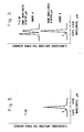
- Fig. 3 there is shown the excitation spectra for a commercially available Nd:YAG crystal, obtained at 6.8K by selective site spectroscopy using the experimental test set-up described in Fig. 4 below.
- a sample of a commercially available Nd:YAG crystal (for example, from Litton Airtron of Morris Plains, New Jersey) containing 1 atomic percent of neodymium dopant and having dimensions of 3 to 6 millimeters in diameter and approximately 6 millimeters in length was used.
- a tunable dye laser of 0.5 centimeter -1 linewidth and output powers in the range of 0.3 to 1.0 watt was used to excite fluorescence of the crystal.
- the dye laser was tuned to the peak of a strong absorption line and the fluorescence spectrum shown as Curve B of Fig. 3 was recorded. However, the detected fluorescence showed weak sidebands, such as at point "Z" of Curve B. Subsequently, the dye laser was tuned off the peak of the absorption line, to enhance this sideband fluorescence, and the spectrum shown in Fig. 3, Curve A was obtained. As shown in Fig. 3, Curve A, an "extra" fluorescence output was obtained at approximately 0.8751 micrometers, as well as the main output at approximately 0.8754 micrometers.
- the temperature variation of quantum efficiency is due to the transfer of energy through the crystal lattice from neodymium ions in the first or normal site at 0.8754 micrometer to neodymium ions in the second or defect-related site at 0.8751 micrometer, with this transfer being strongly temperature-dependent.
- the defect-related dopant site acts as an energy sink, giving up the transferred energy to the crystal lattice, which becomes heat.
- the neodymium ions in the normal site are robbed of the energy needed to produce an efficient fluorescence output.
- the quantum efficiency is regulated only by neodymium ions in the second site.
- this energy transfer mechanism is greatly reduced and neodymium ions in the first site are no longer controlled by neodymium ions in the second site.
- this maximized lasing efficiency is accomplished by improving anion stoichiometry in the Nd:YAG crystal as formed and thus eliminating the anion off-stoichiometry which causes the undesired defect-related sites for the Nd 3+ ions.
- all or most of the Nd 3+ ions are located in the normal sites, and few, if any, Nd 3+ ions are located in sites associated with anion or anion-related defects in the crystal, since the source of these defects has been removed.
- FIG. 4 there is shown, in schematic form, an experimental test set-up which was used to generate the site selection spectra shown in Fig. 3 and discussed above.
- a laser 50 produces an output beam 52 of a specified wavelength, which is stabilized by an internal etalon and power feedback network. Room temperature fluorescence output can be measured using argon laser excitation, while low temperature fluorescence output measurements require a dye laser tuned to a specific absorption line.
- the beam 52 strikes the beam splitter 54, to split the beam into the portions 53 and 55.
- the beam portion 53 strikes the thermopile 57 which measures the power incident on the Nd-doped YAG sample 64.
- the beam portion 55 passes through the focusing lens 56 whereby the beam 55 is focused to a point in the plane of blade 58 of a motor driven chopper 60, which turns the beam 55 on and off, to provide a means to measure the fluorescence rise and decay rates.
- the focused beam passes through a collimating lens 62 and then strikes the Nd-doped YAG laser rod sample 64.
- the laser rod sample may be contained in a heater or on a cold finger in the vacuum space of a transmission dewar (not shown).
- the laser beam striking the Nd:YAG sample 64 causes the sample 64 to produce fluorescent rays 65 which are collected by the spherical mirror 66, having a 0.25 meter radius.
- the mirror 66 reflects the fluorescent rays and images then on an interference filter 68 which passes a preselected wavelength of radiation, such as 1.06 micrometer radiation.
- the radiation passed by filter 68 strikes the detector 70 which may be a monochromator used to resolve the crystal fluorescence transition lines, or a power meter equipped with a suitable filter and used to measure fluorescence output power per absorbed laser excitation power and thus provide quantum efficiency data.
- a portion of the laser beam which strikes the Nd:YAG sample 64 is transmitted thereby and detected by the thermopile 74.
- the test set-up shown in Fig. 4 was used to generate the spectra shown in Fig. 3 and discussed above.
- Fig. 5 there is shown the fluorescence spectrum generated at 8K by using selective site spectroscopy for a Nd:YAG crystal containing 1 atomic percent of neodymium, which has been formed in accordance with the second process embodiment of the present invention described below with regard to Fig. 6.
- This process includes, among other things, reactive atmosphere processing of a commercially available Nd:YAG powder with 1 2 and O2, C0 2 laser melting of the treated powder, and growth of a Nd:YAG crystal from the melt under the reactive atmosphere.
- the spectrum shown in Fig. 5 was generated in the manner previously described in relation to Fig. 3, Curve A. The dye laser was first tuned to the peak of a strong absorption line and a fluorescence spectrum nearly identical to that shown in Fig.
- Fig. 5 was obtained. Then, the dye laser was tuned off the peak of the absorption line to try to enhance the sideband absorption, and the fluorescence spectrum shown in Fig. 5 was obtained. As indicated in Fig. 5 at the point designated "X", there is no sideband absorption, which indicates that the defect-related fluorescence output has been essentially removed from the Nd:YAG crystal has a single dopant site, which provides a fluorescence output at 0.8754 micrometer. Fig. 5 should be compared to Fig. 3, Curve A which indicates the fluorescence output for an untreated Nd:YAG material, in which sideband absorption due to defect-related dopant sites is present.
- a neodymium-doped YAG material having maximized lasing efficiency heretofore unobtained, is produced.
- This new Nd:YAG material is characterized by having neodymium ions located in a single selected site of the YAG crystal structure, which is the "normal" dodecahedral site substantially free of lattice defects induced by anion or anion-related impurities in the crystal. In particular, these lattice defects would arise from anion off-stoichiometry in the crystal.
- these preferentially located neodymium ions undergo a preferential radiative transition and produce a fluorescence output of a specified wavelength, which thereby maximizes the lasing efficiency of the Nd:YAG material, to provide a value close to the theoretically possible value of 91 percent at room temperature.
- the laser threshold, power supply requirements, and laser dimensions may be advantageously reduced.
- the heat load on the laser crystal is reduced, which, in turn, removes thermal distortions and increases beam brightness, to permit ranging at increased distances for a given power input, as compared to some prior art lasers.
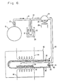
- Fig. 6 shows, in schematic form, one apparatus suitable for generating the reactive atmosphere required in several process embodiments of the present invention.
- the apparatus of Fig. 6 is known from U.S. Patent No. 4,315,832 and FR-A-2 450 885, respectively).
- High purity oxygen (99.99% pure) is provided in a container 10 which is connected to a valve 12, which is connected at its other end to the quartz or pyrex tubing 14.
- the tubing 14 is connected to a water trap device 16 that is immersed in a mixture of dry ice and acetone 18 in the container 20.
- the quartz or pyrex tubing 22 which emerges as shown from the exit of the water trap device 16 leads to a quartz or pyrex container 24 which holds iodine (1 2 ) initially in solid form.
- the solid iodine forms the liquid 28 and is then vaporized.
- the temperature in the container 24 may be controlled to produce sufficient vapor pressure directly from the solid iodine.
- the 1 2 vapor mixed with the dried 0 2 gas in the container 24 passes through the Teflon tube 30 to a connecting high purity (99.9%) alumina tube 32 which passes through a Teflon or vitreous silica cap 33 and then into a high purity alumina reaction tube 34.
- reaction tube 34 there are one or more platinum-lined alumina boats 36 which contain the selected material 38 to be processed.
- the reaction tube 34 also has a high purity alumina tube 40 through which exhaust gases are removed from the reaction tube 34.
- the reaction tube 34 is contained within a furnace 42 which has heating elements 44 that can be controlled to raise the temperature in the furnace 42 to a predetermined level at which atomic oxygen and atomic iodine are formed from the 0 2 and I 2 .
- the method of use of the apparatus shown in Fig. 6 is described in greater detail below.
- the apparatus shown in Fig. 6 may be altered as required to accommodate the use of other atomic oxygen-producing substances, such as a mixture of iodine and nitrous oxide (N 2 0); ozone (0 3 ); or molecular oxygen (0 2 ) under electric discharge.
- the apparatus of Fig. 6 may be combined with an apparatus suitable for crystal growth from a melt, with the reaction tube 34 and associated heating elements shown in Fig. 6 being replaced by a crystal growth chamber and associated heating means.
- the minimization of undesired anion off-stoichiometry and the associated undesired defect-related dopant sites in the Nd:YAG crystal is achieved by first preparing a powder of mixed oxides, comprising, for example, Y 2 0 3 , Nd 2 0 3 , and A1 2 0 3 in the molar ratio of 2.97:0.03:5.00.
- the powder is placed in a crystal growth apparatus which is suitable for crystal growth from a melt and in which a reactive atmosphere can be maintained.
- Such a crystal growth process may be, for example, the known Czochralski method or vertical pull method, in which a seed crystal is immersed in a melt and is then rotated while being slowly withdrawn from the melt. The heating of the melt and the rate of pulling the crystal from the melt are controlled to provide a crystal of the desired size and shape.
- the Czochralski method is described in more detail by J. C. Brice in the book entitled “The Growth of Crystals from Liquids", North-Holland Publishing Company, 1973.
- crystal growth may be performed by the Bridgman method, as described, for example, by Brice as referenced above.
- the apparatus shown in Fig. 6 is used to generate the reactive atmosphere of atomic iodine and atomic oxygen, with the reaction chamber 34 and associated heating elements being replaced by the crystal growth chamber and its associated heating means.
- reactive atmosphere processing is used to remove water and water-derived impurities from the metal oxide powder in order to remove defect-related sites and maximize normal sites for dopants in the crystal structure subsequently formed.
- the oxide powder is placed in a crucible in the crystal growth apparatus, which is then sealed.
- the temperature in the crystal growth chamber is raised at 1500°C.
- High purity 0 2 is introduced from the container 10 through the valve 12 at a flow rate of 6 to 7 cubic centimeters per minute into the cold trap 16, where residual water is removed from the 0 2 by freezing in the dry ice/ acetone mixture 18.
- the dried 0 2 is then passed into the container 24 containing iodine vapor.
- the iodine vapor is produced by activating the heating element 26, which is a nichrome wire, by applying a controlled voltage to this wire, to raise the temperature in the container 24 to approximately 100°C to vaporize the 1 2 .
- the mixture of dry 0 2 and 1 2 have mole concentrations in the ratio of 10:1.
- the O2 and 1 2 mixture then passes through tubes 30 and 32 into the crystal growth chamber.
- the powder is kept at approximately 1500°C for on the order of 100 hours.
- the reactive atmosphere of 0 2 and 1 2 reacts to produce atomic iodine and atomic oxygen, which react with an remove the water and water-derived impurities from the mixed oxide powder.
- the reaction time may be reduced, but both quantities depend upon the particle size of the oxide powder.
- the reactive atmosphere is maintained and the powder is melted by exposure to a laser beam from a C0 2 laser, for example, or by application of heat. Then, the Nd:YAG crystal is grown by the known Czochralski process, for example, under the reactive atmosphere.
- the oxide may first be purified by treatment in the apparatus shown in Fig. 6, using a reactive atmosphere of iodine and oxygen as previously described. After the oxide powder has been purified, it is then transferred to a suitable crystal growth apparatus, the powder is melted, and the crystal is grown from the melt, as discussed above. However, care must be taken at all times during the transfer of the powder to the crystal growth chamber, as well as during the crystal growth process, to assure that the purified powder and the crystal melt subsequently formed thereon are protected from any source of water contamination. This protection can best be accomplished by maintaining the powder or melt under the reactive atmosphere of 1 2 and 0 2 as described above. Alternatively, the purified powder may be protected from water contamination by an inert atmosphere, such as helium, rather than by the reactive atmosphere.
- an inert atmosphere such as helium
- the anion or anion-related impurities which cause unwanted defect-related dopant sites in the YAG crystal have been eliminated. Consequently, upon growth of the neodymium-doped YAG material, the neodymium dopant ions are located in the preferential single crystal site which is substantially free of crystal defects. As previously discussed herein, this preferential single crystal site (i.e., the normal site) for the neodymium dopant produces maximized lasing efficiency in the Nd:YAG crystal.
- a Nd:YAG crystal rod is treated with ozone at 1500°C or higher.
- An apparatus somewhat similar to that shown in Fig. 6 is used with the 1 2 and 0 2 portions being replaced by an ozone-generating system.
- the crystal rod sample is substituted for the powder 38 shown in Fig. 6.
- a Nd:YAG crystal rod is treated with an 1 2 and 0 2 reactive atmosphere, using the apparatus shown in Fig. 6 and substituting the crystal rod sample for the powder 38 shown in Fig. 6.
- the atomic oxygen and atomic iodine formed react with and remove water and water-derived impurities from the YAG crystal.
- this process is performed under high pressure, such as 980 bar (100 atmospheres) or more, which promotes a condition in the crystal structure whereby the location of dopant ions in the normal site is preferred.
- the scope of the invention is not limited to Nd-doped YAG crystals, but is intended to include other lasing ions, such as rare earth ions and transition metal ions, and other oxide crystals and glass host materials, such as yttrium aluminum oxide (YA10 3 ), gadolinium gallium garnet (Gd 3 Ga 5 O 12 ), yttrium vanadate (YV0 4 ), yttrium oxide (Y 2 0 3 ), calcium tungstate (CaW0 4 ), calcium molybdate (CaMo0 4 ), spinel (MgO ⁇ Al 2 O 3 ), chrysoberyl (BeO ⁇ AI 2 0 3 ), sapphire (AI 2 0 3 ), and glass.
- yttrium aluminum oxide YA10 3
- gadolinium gallium garnet Gd 3 Ga 5 O 12
- YV0 4 yttrium vanadate
- Y 2 0 3 yttrium oxide
- the present invention limited to laser materials, but includes any material in which radiation emission is extracted as a result of a given energy input, including, for example, phosphorescent material.
- the basic concept of the present invention i.e., locating dopant ions at a selected site of the host crystal structure during crystal growth, to optimize a radiation emission, applies as well to host crystals other than oxides, such as halides and sulfides.
- host crystals other than oxides such as halides and sulfides.
- alternative processes or reactive atmospheres for producing the desired effect other than those described herein for oxides, must be used which are compatible with the chemical properties of these other materials.
- the process of the present invention has been described herein with respect to laser oxide materials with cation-dopants, it is anticipated that the present invention would apply as well to maximizing the lasing efficiency of stoichiometric laser crystals, in which the laser active ion is a constituent of the crystal structure, rather than a dopant ion, such as neodymium ultra-phosphate (NdP 5 0 12 ) or holmium fluoride.
- a dopant ion such as neodymium ultra-phosphate (NdP 5 0 12 ) or holmium fluoride.
Landscapes
- Chemical & Material Sciences (AREA)
- Engineering & Computer Science (AREA)
- Crystallography & Structural Chemistry (AREA)
- Materials Engineering (AREA)
- Metallurgy (AREA)
- Organic Chemistry (AREA)
- Electromagnetism (AREA)
- Physics & Mathematics (AREA)
- Inorganic Chemistry (AREA)
- Plasma & Fusion (AREA)
- Optics & Photonics (AREA)
- Crystals, And After-Treatments Of Crystals (AREA)
- Lasers (AREA)
Claims (11)
Applications Claiming Priority (2)
| Application Number | Priority Date | Filing Date | Title |
|---|---|---|---|
| US27067481A | 1981-06-04 | 1981-06-04 | |
| US270674 | 1981-06-04 |
Publications (3)
| Publication Number | Publication Date |
|---|---|
| EP0067521A2 EP0067521A2 (fr) | 1982-12-22 |
| EP0067521A3 EP0067521A3 (en) | 1984-11-28 |
| EP0067521B1 true EP0067521B1 (fr) | 1987-07-08 |
Family
ID=23032314
Family Applications (1)
| Application Number | Title | Priority Date | Filing Date |
|---|---|---|---|
| EP82302369A Expired EP0067521B1 (fr) | 1981-06-04 | 1982-05-10 | Procédé pour optimaliser l'efficacité d'un cristal de laser par l'introduction de sites singuliers destinés au dopant |
Country Status (2)
| Country | Link |
|---|---|
| EP (1) | EP0067521B1 (fr) |
| DE (1) | DE3276735D1 (fr) |
Cited By (2)
| Publication number | Priority date | Publication date | Assignee | Title |
|---|---|---|---|---|
| JP2002220287A (ja) * | 2001-01-19 | 2002-08-09 | Shinetsu Quartz Prod Co Ltd | 透光性セラミックス及びその製造方法 |
| EP3985082A4 (fr) * | 2019-08-21 | 2023-02-15 | Meishan Boya Advanced Materials Co., Ltd. | Procédé et dispositif de croissance de cristaux d'oxyde sans recuit |
Families Citing this family (3)
| Publication number | Priority date | Publication date | Assignee | Title |
|---|---|---|---|---|
| CA1207998A (fr) * | 1982-11-23 | 1986-07-22 | Union Carbide Corporation | Obtention de cristaux de grenat pour laser, exempts d'impuretes sous forme d'eau et d'ions hydroxyles |
| JP4605729B2 (ja) * | 2001-01-19 | 2011-01-05 | 信越石英株式会社 | 透光性セラミックス体及びその製造方法 |
| US8039413B2 (en) | 2008-10-24 | 2011-10-18 | Lawrence Livermore National Security, Llc | Transparent ceramics and methods of preparation thereof |
Family Cites Families (2)
| Publication number | Priority date | Publication date | Assignee | Title |
|---|---|---|---|---|
| FR1453868A (fr) * | 1964-05-18 | 1966-07-22 | Union Carbide Corp | Cristaux et procédé permettant de les faire croître |
| US4315832A (en) * | 1979-03-05 | 1982-02-16 | Hughes Aircraft Company | Process for increasing laser crystal fluorescence yield by controlled atmosphere processing |
-
1982
- 1982-05-10 EP EP82302369A patent/EP0067521B1/fr not_active Expired
- 1982-05-10 DE DE8282302369T patent/DE3276735D1/de not_active Expired
Cited By (3)
| Publication number | Priority date | Publication date | Assignee | Title |
|---|---|---|---|---|
| JP2002220287A (ja) * | 2001-01-19 | 2002-08-09 | Shinetsu Quartz Prod Co Ltd | 透光性セラミックス及びその製造方法 |
| EP3985082A4 (fr) * | 2019-08-21 | 2023-02-15 | Meishan Boya Advanced Materials Co., Ltd. | Procédé et dispositif de croissance de cristaux d'oxyde sans recuit |
| US11828001B2 (en) | 2019-08-21 | 2023-11-28 | Meishan Boya Advanced Materials Co., Ltd. | Methods and devices for growing oxide crystals in oxygen atmosphere |
Also Published As
| Publication number | Publication date |
|---|---|
| DE3276735D1 (en) | 1987-08-13 |
| EP0067521A3 (en) | 1984-11-28 |
| EP0067521A2 (fr) | 1982-12-22 |
Similar Documents
| Publication | Publication Date | Title |
|---|---|---|
| Baryshevsky et al. | Spectroscopy and scintillation properties of cerium doped YAlO3 single crystals | |
| US4315832A (en) | Process for increasing laser crystal fluorescence yield by controlled atmosphere processing | |
| US5164041A (en) | Method of growing rare earth doped orthosilicates(ln2-xrexsio5) | |
| Shimamura et al. | Growth of Ce-doped LiCaAlF6 and LiSrAlF6 single crystals by the Czochralski technique under CF4 atmosphere | |
| Foulon et al. | Laser heated pedestal growth and optical properties of Yb3+-doped LiNbO3 single crystal fibers | |
| US4962504A (en) | Mixed lanthanide-magnesium aluminates and lasers using monocrystals of these aluminates | |
| US6839362B2 (en) | Cobalt-doped saturable absorber Q-switches and laser systems | |
| US3866142A (en) | Doped beryllium lanthanate crystals | |
| Richter | Laser Parameters and Performance of Pr_1hn3_1hn+-doped Fluorides Operating in the Visible Spectral Region | |
| EP0067521A2 (fr) | Procédé pour optimaliser l'efficacité d'un cristal de laser par l'introduction de sites singuliers destinés au dopant | |
| US3769230A (en) | Calcium fluoride-rare earth fluoride fluorescent compound useful as alaser crystal | |
| US3550033A (en) | Chromium-doped gdalo3 high energy storage laser material | |
| Borkowski et al. | Chemical synthesis and crystal growth of laser quality praseodymium pentaphosphate | |
| US4124524A (en) | Neodymium ultraphosphates and process for their preparation | |
| Jacobsen et al. | New methods for studying the optical properties of metal ions in solids | |
| Gorbachenya et al. | Continuous-wave Laser on Er, Yb-Codoped Pentaborate Crystal | |
| Parisi et al. | Fluoride crystals: materials for near-infrared solid state lasers | |
| US3983051A (en) | Doped beryllium lanthanate crystals | |
| Dianov et al. | Synthesis and investigation of spectral, luminescence, and lasing properties of alumoborate crystals activated with chromium and neodymium ions | |
| Baldochi et al. | A short review on fluoride laser crystals grown by Czochralski method at IPEN | |
| Chang et al. | Fabrication of laser materials by laser-heated pedestal growth | |
| Werkhoven et al. | Annihilation of frozen‐in point defects in GaP by thermal and recombination‐induced processes | |
| RU2202010C1 (ru) | Способ получения монокристаллического оксида цинка с быстрым излучением в ультрафиолетовой области спектра | |
| Papadopoulo et al. | Properties of homogeneously doped ZnSe single crystals obtained by a new growth method | |
| Püschel | Anti-Stokes fluorescence cooling of ytterbium-doped fluoride crystals |
Legal Events
| Date | Code | Title | Description |
|---|---|---|---|
| PUAI | Public reference made under article 153(3) epc to a published international application that has entered the european phase |
Free format text: ORIGINAL CODE: 0009012 |
|
| AK | Designated contracting states |
Designated state(s): DE FR GB IT NL |
|
| PUAL | Search report despatched |
Free format text: ORIGINAL CODE: 0009013 |
|
| AK | Designated contracting states |
Designated state(s): DE FR GB IT NL |
|
| 17P | Request for examination filed |
Effective date: 19850502 |
|
| 17Q | First examination report despatched |
Effective date: 19860430 |
|
| RAP1 | Party data changed (applicant data changed or rights of an application transferred) |
Owner name: HUGHES AIRCRAFT COMPANY |
|
| ITF | It: translation for a ep patent filed | ||
| GRAA | (expected) grant |
Free format text: ORIGINAL CODE: 0009210 |
|
| AK | Designated contracting states |
Kind code of ref document: B1 Designated state(s): DE FR GB IT NL |
|
| REF | Corresponds to: |
Ref document number: 3276735 Country of ref document: DE Date of ref document: 19870813 |
|
| ET | Fr: translation filed | ||
| PLBE | No opposition filed within time limit |
Free format text: ORIGINAL CODE: 0009261 |
|
| STAA | Information on the status of an ep patent application or granted ep patent |
Free format text: STATUS: NO OPPOSITION FILED WITHIN TIME LIMIT |
|
| 26N | No opposition filed | ||
| ITTA | It: last paid annual fee | ||
| PGFP | Annual fee paid to national office [announced via postgrant information from national office to epo] |
Ref country code: FR Payment date: 19940413 Year of fee payment: 13 |
|
| PGFP | Annual fee paid to national office [announced via postgrant information from national office to epo] |
Ref country code: GB Payment date: 19940419 Year of fee payment: 13 |
|
| PGFP | Annual fee paid to national office [announced via postgrant information from national office to epo] |
Ref country code: DE Payment date: 19940425 Year of fee payment: 13 |
|
| PGFP | Annual fee paid to national office [announced via postgrant information from national office to epo] |
Ref country code: NL Payment date: 19940531 Year of fee payment: 13 |
|
| PG25 | Lapsed in a contracting state [announced via postgrant information from national office to epo] |
Ref country code: GB Effective date: 19950510 |
|
| PG25 | Lapsed in a contracting state [announced via postgrant information from national office to epo] |
Ref country code: NL Effective date: 19951201 |
|
| GBPC | Gb: european patent ceased through non-payment of renewal fee |
Effective date: 19950510 |
|
| NLV4 | Nl: lapsed or anulled due to non-payment of the annual fee |
Effective date: 19951201 |
|
| PG25 | Lapsed in a contracting state [announced via postgrant information from national office to epo] |
Ref country code: DE Effective date: 19960201 |
|
| PG25 | Lapsed in a contracting state [announced via postgrant information from national office to epo] |
Ref country code: FR Effective date: 19960229 |
|
| REG | Reference to a national code |
Ref country code: FR Ref legal event code: ST |
|
| REG | Reference to a national code |
Ref country code: FR Ref legal event code: ST |