EP0067522A2 - Cellule blindée pourvue d'un manipulateur maître-esclave - Google Patents
Cellule blindée pourvue d'un manipulateur maître-esclave Download PDFInfo
- Publication number
- EP0067522A2 EP0067522A2 EP82302378A EP82302378A EP0067522A2 EP 0067522 A2 EP0067522 A2 EP 0067522A2 EP 82302378 A EP82302378 A EP 82302378A EP 82302378 A EP82302378 A EP 82302378A EP 0067522 A2 EP0067522 A2 EP 0067522A2
- Authority
- EP
- European Patent Office
- Prior art keywords
- arm
- sealed
- slave
- replacement
- linking part
- Prior art date
- Legal status (The legal status is an assumption and is not a legal conclusion. Google has not performed a legal analysis and makes no representation as to the accuracy of the status listed.)
- Granted
Links
Images




Classifications
-
- B—PERFORMING OPERATIONS; TRANSPORTING
- B25—HAND TOOLS; PORTABLE POWER-DRIVEN TOOLS; MANIPULATORS
- B25J—MANIPULATORS; CHAMBERS PROVIDED WITH MANIPULATION DEVICES
- B25J3/00—Manipulators of leader-follower type, i.e. both controlling unit and controlled unit perform corresponding spatial movements
-
- G—PHYSICS
- G21—NUCLEAR PHYSICS; NUCLEAR ENGINEERING
- G21F—PROTECTION AGAINST X-RADIATION, GAMMA RADIATION, CORPUSCULAR RADIATION OR PARTICLE BOMBARDMENT; TREATING RADIOACTIVELY CONTAMINATED MATERIAL; DECONTAMINATION ARRANGEMENTS THEREFOR
- G21F7/00—Shielded cells or rooms
- G21F7/06—Structural combination with remotely-controlled apparatus, e.g. with manipulators
- G21F7/061—Integrated manipulators
- G21F7/062—Integrated manipulators mounted in a wall, e.g. pivotably mounted
-
- Y—GENERAL TAGGING OF NEW TECHNOLOGICAL DEVELOPMENTS; GENERAL TAGGING OF CROSS-SECTIONAL TECHNOLOGIES SPANNING OVER SEVERAL SECTIONS OF THE IPC; TECHNICAL SUBJECTS COVERED BY FORMER USPC CROSS-REFERENCE ART COLLECTIONS [XRACs] AND DIGESTS
- Y10—TECHNICAL SUBJECTS COVERED BY FORMER USPC
- Y10T—TECHNICAL SUBJECTS COVERED BY FORMER US CLASSIFICATION
- Y10T29/00—Metal working
- Y10T29/49—Method of mechanical manufacture
- Y10T29/49718—Repairing
- Y10T29/49721—Repairing with disassembling
- Y10T29/4973—Replacing of defective part
-
- Y—GENERAL TAGGING OF NEW TECHNOLOGICAL DEVELOPMENTS; GENERAL TAGGING OF CROSS-SECTIONAL TECHNOLOGIES SPANNING OVER SEVERAL SECTIONS OF THE IPC; TECHNICAL SUBJECTS COVERED BY FORMER USPC CROSS-REFERENCE ART COLLECTIONS [XRACs] AND DIGESTS
- Y10—TECHNICAL SUBJECTS COVERED BY FORMER USPC
- Y10T—TECHNICAL SUBJECTS COVERED BY FORMER US CLASSIFICATION
- Y10T29/00—Metal working
- Y10T29/49—Method of mechanical manufacture
- Y10T29/49815—Disassembling
- Y10T29/49822—Disassembling by applying force
Definitions
- This invention relates to shielded cells having manipulators comprising a master arm and a slave arm with a linking part between the arms.
- alpha-emitting materials such as plutonium.
- any shielded cell therefore is expected to have a high standard of containment of such air-borne substances at all times.
- alpha-emitting materials have been handled in a compartment (sometimes called a "glove box").
- the master-slave manipulator is sealed in the glove box and the slave arm is encased in a sealing gaiter which extends from the shoulder to the wrist-
- a complicated procedure of introducing the slave arm into protective bags is adopted and, whilst this is intended to maintain a high standard of containment, possibilities arise that slight air-borne contamination can reach operator occupied regions.
- this known procedure is quite adequate but for a much reduced limit on alpha contamination (eg 1% of the currently accepted maximum permissible limit) improved methods of removing slave arms are required.
- the present invention provides such improved methods.
- the present invention provides a shielded cell having a manipulator comprising a master arm and a slave arm sealed in the cell with a linking part between the arms characterised in that the linking part is demountable in a manner to permit the insertion of a replacement slave unit which can eject the existing slave arm into its contaminated environment without breaching the cell seal and then replace the existing slave arm, said replacement unit comprising a replacement slave arm preceded by an intermediate sealing body sealed with the replacement arm by a sealed flexible gaiter which is decouplable, also into said contaminated environment, once the seal of the replacement arm in the cell is set up.
- the invention is further extended with advantage by providing the cell as a sealed compartment spaced from a shield wall to provide an interspace accessible to a protected operator and the linking part of the manipulator is demountable and spans from the shield wall to the sealed compartment and the replacement slave unit is insertable into the sealed compartment from the interspace when the linking part is demounted.
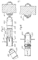
- FIG. 1 there is shown a shielded cell comprising a shield wall 10 permitting unprotected operator access in the region numbered 11 and a sealed compartment 12 spaced from the wall 10 by an interspace 13.
- a master/slave manipulator comprising a master arm 14, a slave arm 15 and a linking part 16 between the arms.
- the part 16 has a number of sub-parts. These include a master arm support sleeve 21 sealed by sealing rings 22 in an aperture tube 23 in the wall 10, demountable coupling 24 and a slave arm support sleeve 25 sealed by rings 26 in an aperture tube 27 in the compartment 12. A further demountable coupling 20 is provided for the master arm.
- the coupling 20 is accessible to a nominally unprotected operator in region 11 whilst the coupling 24, being between the wall 10 and compartment 12, is accessible to an operator in the interspace 13 having protective clothing.
- the coupling 24 has a sleeve split into upper and lower parts 30, 31 which are normally secured together by bolts 33.
- Each part 30, 3 1 has a pair of slotted lugs 34 ( Figure 4) which engage on heads 35 so that rotary motion can be transmitted from a flange 36 to the flanges 37 on the parts 30, 31 and thence to a flange 38.
- linear reciprocating parts 40, 41 joined by a coupling 42 are exposed.
- Parts 41 have bellows 43 to seal them in passage through flange 38.
- Figure 3 shows the coupling 42 disconnected and the part 40, 41 moved apart.
- the coupling 20 is very similar in construction to that of coupling 24 and is not described in detail.
- FIG 5 the master/slave manipulator is separated into its parts and the dis-assembly procedure is shown.
- Arrow 50 shows the direction of movement of the slave arm (represented by support sleeve 25) into the sealed compartment 12 whence it can be removed via an air lock.
- Arrow 51 shows the direction of movement of the master arm support leeve 21 into the interspace where it is gathered by an operator using protective clothing. This operator has previously gathered the demounted coupling 2u.
- the master arm 14 is removed by the nominally unprotected operator together with the demounted coupling 20.
- the split sleeve form of coupling 24 is not essential and other couplings capable of transmitting the required torque between flanges 36 and 38 could be provided.
- FIG 6 the situation is shown in which the master arm support sleeve 21 and slave arm support sleeve 25 of Figure 1 remains in position but the coupling 24 has been removed and a replacement slave arm assembly 100 is arranged in the interspace 13 between the wall 10 and the compartment 12.
- the assembly 100 comprises a replacement slave arm support sleeve 125 having sealing rings 126 and carrying a slave arm 115.
- An intermediate sealing body in the form of a sleeve 101 is provided and this sleeve has external sealing rings 102 and is coupled to the support sleeve 125 by a flexible bag 103.
- the sleeve 101 has been pushed into the tube 27 by a protected operator in the interspace 13 to displace the support sleeve 25 into the compartment 12.
- the , bag 103 is extended and there has been no breach of the containment as either a sealing ring 26 or 102 maintains a seal and the bag isolates the interspace 13 from the interior of the compartment 12.
- the sleeve 125 is advanced into the tube 27 to displace, in turn, the sleeve 101 into the compartment. Again there is no breach of the containment as either a sealing ring 102 or 126 maintains, with the bag 103, a seal.
- the sleeve 101 and bag 103 can then be detached within the compartment 12 by heat cutting the bag where it joins the support sleeve 125 by devices within the compartment 12 operated through gloved ports.
- the support sleeve 125 can then be connected to the support sleeve 21 by reconnecting the coupling 24.
- the support sleeve 21 can also be replaced before connecting to the sleeve 125 by means of the coupling 24.
- a bagging ring 104 is mounted at the inner end of the tube 23 in the wall 10 and a plastics bag 105 is attached to the ring 104.
- the support sleeve 21 is pushed into the bag by a replacement support sleeve 121 from outside the shield wall 10 and the bag 105 ensures that there is no direct access between the interspace 13 and the outside of the shield wall 1 0.
- the bag 105 containing the support sleeve 21 is then removed from the bagging ring 104 and can be heat sealed before removal from the interspace.
- the replacement support sleeve 121 can be then joined to the replacement support sleeve 125 by the coupling 24.
- the coupling 20 and master arm . 14 are replaced to allow operation of the "new"manioulator.
- Items displaced into the compartment 12 can be allowed to remain as debris on the floor of the compartment or removed through ports, provided for that purpose, into shielded disposal containers.
- FIG 11 there is shown a modified arrangement which has been shown in the context of a shielded cell having a single shield wall 210 (which could also be wall 10 or 12).
- Aperture tube 223 in the wall 210 (or tube 27 in wall 12) is provided with bagging ring 204 on the side of the wall exposed to radiation.
- a bag 205 is attached to the ring 204 through gloves in glove posts to receive an "old" manipulator assembly 15 which is displaced by a "new" manipulator assembly 215.
- the "old” assembly is pushed out of the tube 223 by the end sleeve 201 which is coupled to the "new" support sleeve 225 by bag 203.
- the sleeve 201 is provided with sealing rings 202 which engage the tube 223.
- the bag containing the "old" manipulator can then be removed and sealed.
- the arm of the "new” manipulator is advanced through the tube 223 until the sleeve 225 abuts against the sleeve 201. At this position the bag 203 is compressed.
- the manipulator arm can be contained within a gaiter 206.
- a similar gaiter can also be provided about the slave arm in Figures 6 to 8.
- a typical spacing between walls 10 and 12 of Figure 1 is 1 metre.
- a typical manipulator slave arm may be about 1.5 to 2.0 metres. It is seen from Figure 11 that the manipulator has an elbow 260 and, by bending the manipulator at the elbow, it is possible to manipulate it in the 1 metre space.
- the replacement slave arm assembly 100 is shown for convenience in line with the aperture tube 27, in practice the assembly 100 can be bent initially and can be manipulated into its working position by a protected operator in the interspace 13.
Landscapes
- Engineering & Computer Science (AREA)
- Robotics (AREA)
- Mechanical Engineering (AREA)
- Physics & Mathematics (AREA)
- General Engineering & Computer Science (AREA)
- High Energy & Nuclear Physics (AREA)
- Manipulator (AREA)
Applications Claiming Priority (4)
| Application Number | Priority Date | Filing Date | Title |
|---|---|---|---|
| GB8115157 | 1981-05-18 | ||
| GB8115157 | 1981-05-18 | ||
| GB8128675 | 1981-09-22 | ||
| GB8128675 | 1981-09-22 |
Publications (3)
| Publication Number | Publication Date |
|---|---|
| EP0067522A2 true EP0067522A2 (fr) | 1982-12-22 |
| EP0067522A3 EP0067522A3 (en) | 1984-04-18 |
| EP0067522B1 EP0067522B1 (fr) | 1986-08-13 |
Family
ID=26279504
Family Applications (1)
| Application Number | Title | Priority Date | Filing Date |
|---|---|---|---|
| EP82302378A Expired EP0067522B1 (fr) | 1981-05-18 | 1982-05-10 | Cellule blindée pourvue d'un manipulateur maître-esclave |
Country Status (3)
| Country | Link |
|---|---|
| US (1) | US4474518A (fr) |
| EP (1) | EP0067522B1 (fr) |
| DE (1) | DE3272546D1 (fr) |
Families Citing this family (7)
| Publication number | Priority date | Publication date | Assignee | Title |
|---|---|---|---|---|
| IE56166B1 (en) * | 1985-02-15 | 1991-05-08 | Tekscan Ltd | Manipulator means |
| US4961273A (en) * | 1987-03-30 | 1990-10-09 | Hull Corporation | Method and means for assuring freeze dryer chamber sterility |
| US4913481A (en) * | 1988-09-13 | 1990-04-03 | Applied Power Inc. | Clean room gripper |
| GB2311955B (en) * | 1996-04-12 | 2000-02-16 | Par Systems Inc | System for performing work in a hot cell |
| FR2797412B1 (fr) * | 1999-08-13 | 2001-10-19 | Sit Soc Innovations Tech | Telemanipulateur |
| US20100158641A1 (en) * | 2008-12-19 | 2010-06-24 | Delaware Capital Formation, Inc. | Manipulator System |
| DE102017102653B4 (de) * | 2017-02-10 | 2024-10-31 | Schunk Gmbh & Co. Kg Spann- Und Greiftechnik | Stabkinematik |
Family Cites Families (7)
| Publication number | Priority date | Publication date | Assignee | Title |
|---|---|---|---|---|
| US312887A (en) * | 1885-02-24 | Loose-pulley lubricator | ||
| FR1248526A (fr) * | 1959-11-05 | 1960-12-16 | Saint Gobain | Perfectionnement aux télémanipulateurs mécaniques |
| DE1250988B (fr) * | 1962-04-30 | |||
| US3475808A (en) * | 1967-03-09 | 1969-11-04 | Atomic Energy Commission | Method of changing gloves in a controlled environment box |
| US3503273A (en) * | 1968-11-08 | 1970-03-31 | Central Research Lab Inc | Wrist joint |
| GB1341489A (en) * | 1971-09-20 | 1973-12-19 | Atomic Energy Authority Uk | Remote handling devices |
| JPS562600A (en) * | 1979-06-21 | 1981-01-12 | Hitachi Cable | Exchanging port structure of operation member in shielding box |
-
1982
- 1982-05-10 DE DE8282302378T patent/DE3272546D1/de not_active Expired
- 1982-05-10 EP EP82302378A patent/EP0067522B1/fr not_active Expired
- 1982-05-17 US US06/378,803 patent/US4474518A/en not_active Expired - Lifetime
Also Published As
| Publication number | Publication date |
|---|---|
| EP0067522A3 (en) | 1984-04-18 |
| EP0067522B1 (fr) | 1986-08-13 |
| US4474518A (en) | 1984-10-02 |
| DE3272546D1 (en) | 1986-09-18 |
Similar Documents
| Publication | Publication Date | Title |
|---|---|---|
| US7282176B2 (en) | Method of mounting a piece of handling equipment to a containment chamber containing a sterile medium | |
| EP0067522B1 (fr) | Cellule blindée pourvue d'un manipulateur maître-esclave | |
| CA1232984A (fr) | Enceinte mobile pour le remplacement et la transport d'elements contamines, et enveloppe complementaire pour ladite enceinte | |
| Desbats et al. | Force‐feedback teleoperation of an industrial robot in a nuclear spent fuel reprocessing plant | |
| US20230364619A1 (en) | Beta component of a transfer system for a sterile isolation region, sterile isolation region, aseptic filling system, and a method of operating such a filling system | |
| EP0030565B1 (fr) | Structure d'orifice de remplacement pour composant changeable dans une boite de protection | |
| US4334896A (en) | Filter replacement process and apparatus | |
| CN117425550A (zh) | 用于密封封围件的包含可变形部分的传输装置 | |
| CN209405298U (zh) | 用于合成放射性药物产品的设备 | |
| JPH0549436B2 (fr) | ||
| US20250196376A1 (en) | Device for manipulating items contained in a glove box while forming a double sealed wall, and associated glove box | |
| US4140453A (en) | Press apparatus enclosure arrangement | |
| US3897089A (en) | Device for the releasable connection of a dual hose system to a closed container | |
| CN114770551A (zh) | 退役机器人 | |
| KR100886638B1 (ko) | 구획실의 외부와 내부 사이를 연결하기 위한 시스템 | |
| Clement et al. | An overview of CAT control in nuclear services | |
| KR100909767B1 (ko) | 홀더 장치 및 이를 갖는 매니퓰레이터 어셈블리 | |
| US5052938A (en) | Through-wall connection assembly | |
| JPH0299896A (ja) | 密封又は生物学的防護を破ること無く、駆動要素及び/又は該駆動要素と照射済物体処理用セルの内側の駆動要素との間の接続部材を交換する方法 | |
| JPH06342096A (ja) | 隔室開口における封止板の隔離方法及び装置 | |
| GB1599699A (en) | Counterweight system for master-slave manipulator | |
| JP4304867B2 (ja) | レーザー用ファイバーのセル内外配線構造 | |
| CN2543185Y (zh) | 一种同位素自动分装装置 | |
| US3510011A (en) | Manipulator for working in non-accessible spaces | |
| JPH0634091B2 (ja) | ペリスコープの放射能汚染防護装置及びその着脱方法 |
Legal Events
| Date | Code | Title | Description |
|---|---|---|---|
| PUAI | Public reference made under article 153(3) epc to a published international application that has entered the european phase |
Free format text: ORIGINAL CODE: 0009012 |
|
| AK | Designated contracting states |
Designated state(s): DE FR GB IT |
|
| PUAL | Search report despatched |
Free format text: ORIGINAL CODE: 0009013 |
|
| AK | Designated contracting states |
Designated state(s): DE FR GB IT |
|
| RAP1 | Party data changed (applicant data changed or rights of an application transferred) |
Owner name: BRITISH NUCLEAR FUELS PLC |
|
| 17P | Request for examination filed |
Effective date: 19840703 |
|
| GRAA | (expected) grant |
Free format text: ORIGINAL CODE: 0009210 |
|
| AK | Designated contracting states |
Kind code of ref document: B1 Designated state(s): DE FR GB IT |
|
| ITF | It: translation for a ep patent filed | ||
| ET | Fr: translation filed | ||
| REF | Corresponds to: |
Ref document number: 3272546 Country of ref document: DE Date of ref document: 19860918 |
|
| PLBE | No opposition filed within time limit |
Free format text: ORIGINAL CODE: 0009261 |
|
| STAA | Information on the status of an ep patent application or granted ep patent |
Free format text: STATUS: NO OPPOSITION FILED WITHIN TIME LIMIT |
|
| 26N | No opposition filed | ||
| ITTA | It: last paid annual fee | ||
| PGFP | Annual fee paid to national office [announced via postgrant information from national office to epo] |
Ref country code: FR Payment date: 20000411 Year of fee payment: 19 |
|
| PGFP | Annual fee paid to national office [announced via postgrant information from national office to epo] |
Ref country code: GB Payment date: 20000419 Year of fee payment: 19 |
|
| PGFP | Annual fee paid to national office [announced via postgrant information from national office to epo] |
Ref country code: DE Payment date: 20000425 Year of fee payment: 19 |
|
| PG25 | Lapsed in a contracting state [announced via postgrant information from national office to epo] |
Ref country code: GB Free format text: LAPSE BECAUSE OF NON-PAYMENT OF DUE FEES Effective date: 20010510 |
|
| GBPC | Gb: european patent ceased through non-payment of renewal fee |
Effective date: 20010510 |
|
| PG25 | Lapsed in a contracting state [announced via postgrant information from national office to epo] |
Ref country code: FR Free format text: LAPSE BECAUSE OF NON-PAYMENT OF DUE FEES Effective date: 20020131 |
|
| PG25 | Lapsed in a contracting state [announced via postgrant information from national office to epo] |
Ref country code: DE Free format text: LAPSE BECAUSE OF NON-PAYMENT OF DUE FEES Effective date: 20020301 |