EP0067554B1 - Mesure de la grandeur des particules - Google Patents
Mesure de la grandeur des particules Download PDFInfo
- Publication number
- EP0067554B1 EP0067554B1 EP82302582A EP82302582A EP0067554B1 EP 0067554 B1 EP0067554 B1 EP 0067554B1 EP 82302582 A EP82302582 A EP 82302582A EP 82302582 A EP82302582 A EP 82302582A EP 0067554 B1 EP0067554 B1 EP 0067554B1
- Authority
- EP
- European Patent Office
- Prior art keywords
- light
- particles
- illuminating
- size
- backscattered
- Prior art date
- Legal status (The legal status is an assumption and is not a legal conclusion. Google has not performed a legal analysis and makes no representation as to the accuracy of the status listed.)
- Expired
Links
- 239000002245 particle Substances 0.000 title claims abstract description 35
- 238000005259 measurement Methods 0.000 title 1
- 238000000034 method Methods 0.000 claims abstract description 10
- 239000012798 spherical particle Substances 0.000 claims abstract description 7
- 230000003287 optical effect Effects 0.000 claims description 6
- 230000005684 electric field Effects 0.000 claims description 5
- 239000013598 vector Substances 0.000 claims description 4
- UBLYEVLMRSPMOG-UHFFFAOYSA-N NCC1CCCC1 Chemical compound NCC1CCCC1 UBLYEVLMRSPMOG-UHFFFAOYSA-N 0.000 description 1
- 238000004590 computer program Methods 0.000 description 1
- 238000001514 detection method Methods 0.000 description 1
- 239000007788 liquid Substances 0.000 description 1
- 238000004513 sizing Methods 0.000 description 1
- 239000007787 solid Substances 0.000 description 1
Images


Classifications
-
- G—PHYSICS
- G01—MEASURING; TESTING
- G01B—MEASURING LENGTH, THICKNESS OR SIMILAR LINEAR DIMENSIONS; MEASURING ANGLES; MEASURING AREAS; MEASURING IRREGULARITIES OF SURFACES OR CONTOURS
- G01B11/00—Measuring arrangements characterised by the use of optical techniques
- G01B11/08—Measuring arrangements characterised by the use of optical techniques for measuring diameters
-
- G—PHYSICS
- G01—MEASURING; TESTING
- G01N—INVESTIGATING OR ANALYSING MATERIALS BY DETERMINING THEIR CHEMICAL OR PHYSICAL PROPERTIES
- G01N15/00—Investigating characteristics of particles; Investigating permeability, pore-volume or surface-area of porous materials
- G01N15/02—Investigating particle size or size distribution
- G01N15/0205—Investigating particle size or size distribution by optical means
- G01N15/0211—Investigating a scatter or diffraction pattern
Definitions
- the present invention is based on a method and an apparatus for determining the size of spherical particles such as known from document GB-A-2054143.
- a number of optical methods for measuring the size of particles are available. For example, the diameters of projected images of the particles can be measured directly. More sophisticated techniques utilise in one way or another variations in the intensity of light which is scattered by the particles. For example, one can measure the changes in the intensity of linearly polarised light reflected or scattered from particles as they traverse a system of interference fringes as in Patent Specification GB-A-2,054,143, or the intensity distribution of unpolarised light scattered by the particles in a foward direction can be utilised to derive an estimation of the size of the scattering particles.
- the present invention bears some similarity to the last mentioned technique, but it operates in a backscatter mode which simplifies the optical arrangements, because only one-sided optical access is required.
- a method of determining the size of spherical particles comprising the operations of illuminating with a beam of polarised light particles the size of which is to be determined, detecting light backscattered by the particles, characterised in that the illuminating light is circularly polarised and there are included the operations of measuring the angular intensity distribution of the backscattered light and deriving therefrom an indication of the sizes of the particles.
- an apparatus for determining the size of spherical particles comprising means for illuminating with a beam of polarised light particles the size of which is to be determined and means for detecting light backscattered from the illuminating beam by the particles characterised by means for circularly polarising the illuminating light and by means for measuring the angular intensity distribution of the backscattered light.
- the illuminating beam of circularly polarised light is derived from a laser source.
- S 1 ( ⁇ ) and S 2 (A) are the scattering functions for the electric field components of a plane electromagnetic wave which is scattered by a spherical particle, normal and perpendicular to the scattering plane, then it can be shown that for a circularly polarised incident beam, the scattered intensity in the backward direction is given by:- and where i is the scattered intensity component rotating in the same sense as the beam which was incident upon the scattering particle when viewed from the same direction in space.! is the intensity of the counter-rotating component and where ⁇ is the wavelength of the incident light, 1 0 its intensity and y the distance from the scattering particle.
- the functions S 1 ( ⁇ ) and S 2 (S) were first determined by Mie in a paper published in Ann. Phys. 1pz. 25,377 (08).
- Figure 1 shows the intensities
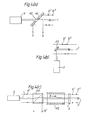
- Figures 2 and 3 illustrate two forms of apparatus for putting the invention into practice. That arrangement which is illustrated in Figure 2, gives 3-dimensional spatial resolution which is suitable particularly for sizing single particles in low density situations. That arrangement which is illustrated in Figure 3 gives only line of sight resolution but is more suitable for use when many particles are under observation.
- a narrow plane polarised beam of light 1 from a laser source 2 is passed through a beam splitter 3 and then a quarter wave plate 4 which converts it into a circularly polarised beam of light 5 which is brought to a focus on a scattering particle 6 by means of a lens 7.
- Scattered light 8 containing components rotating in the same and opposite senses as the light in the beam 5 are converted into two superimposed beams 8' and 8" with their electric field vectors E x and Ey in and perpendicular to the plane of the paper, respectively.
- the beam splitter 3 directs the beams of light 8' and 8" onto a polarisation analyser 9, for example, a Nicol prism, which selects the counter-rotating beam 8' only. This is brought to a focus at an aperture 10 by means of a lens 11, and then falls on an annular shaped detector 12.
- the apparatus shown in Figure 3 is similar to that shown in Figure 2, and corresponding components have the same reference numbers. The differences are that the lens 7 and the aperture 10 are omitted. Also, the detection system 12 is in the Fourier transform plane of the lens 11, and it is arranged to be sensitive only to the angular deviation of the scattered light. Thus the position of any given scattering particle along the axis of the beam of lights is unimportant within the limits of the backscattered lightcollec- tion aperture.
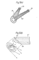
- Figure 5(a) shows two forms of annular detector which can be used.
- the arrangement shown in Figure 5(a) uses concentric annular bundles of optical fibres, two of which are shown.
- Each annular group of fibres 51 and 52 is brought to a circular output at a respective light sensitive diode 53 and 54.
- the photo diodes 53 and 54 can be replaced by photomultipliers.
- Figure 5(b) shows another form of annular detector.
- the annular detector shown in Figure 5(b) consists of a plurality of elliptical mirrors 55 which are regularly displaced relatively to one another in azimuth.
- a plurality of light sensitive diodes or photomultipliers are positioned at known angular locations so as to receive light reflected from the mirrors 55.
- the mirrors 55 are produced by working an end 56 of a bundle of co-axial tubes 57 at an angle of 45° to the axis of the bundle of co-axial tubes 57, rotating the tubes 57 relative to one another and fixing them in the desired positions.
- detectors which are not illustrated are an annular array of self-scanning storage light sensitive diodes, or a spirally scanned television tube.
- the final determination of particle size can be achieved either by carrying out a Fourier transform process on the outputs from the detectors electronically, or by means of a suitable computer program.
Landscapes
- Physics & Mathematics (AREA)
- General Physics & Mathematics (AREA)
- Chemical & Material Sciences (AREA)
- Analytical Chemistry (AREA)
- Health & Medical Sciences (AREA)
- Life Sciences & Earth Sciences (AREA)
- Dispersion Chemistry (AREA)
- Biochemistry (AREA)
- General Health & Medical Sciences (AREA)
- Immunology (AREA)
- Pathology (AREA)
- Investigating Or Analysing Materials By Optical Means (AREA)
- Length Measuring Devices By Optical Means (AREA)
- Analysing Materials By The Use Of Radiation (AREA)
Claims (13)
Priority Applications (1)
| Application Number | Priority Date | Filing Date | Title |
|---|---|---|---|
| AT82302582T ATE19302T1 (de) | 1981-06-04 | 1982-05-20 | Messung der teilchengroesse. |
Applications Claiming Priority (2)
| Application Number | Priority Date | Filing Date | Title |
|---|---|---|---|
| GB8117190 | 1981-06-04 | ||
| GB8117190 | 1981-06-04 |
Publications (2)
| Publication Number | Publication Date |
|---|---|
| EP0067554A1 EP0067554A1 (fr) | 1982-12-22 |
| EP0067554B1 true EP0067554B1 (fr) | 1986-04-16 |
Family
ID=10522287
Family Applications (1)
| Application Number | Title | Priority Date | Filing Date |
|---|---|---|---|
| EP82302582A Expired EP0067554B1 (fr) | 1981-06-04 | 1982-05-20 | Mesure de la grandeur des particules |
Country Status (5)
| Country | Link |
|---|---|
| US (1) | US4492467A (fr) |
| EP (1) | EP0067554B1 (fr) |
| AT (1) | ATE19302T1 (fr) |
| DE (1) | DE3270572D1 (fr) |
| DK (1) | DK245882A (fr) |
Families Citing this family (25)
| Publication number | Priority date | Publication date | Assignee | Title |
|---|---|---|---|---|
| US4652755A (en) * | 1985-01-10 | 1987-03-24 | Advanced Fuel Research, Inc. | Method and apparatus for analyzing particle-containing gaseous suspensions |
| US4890920A (en) * | 1986-02-12 | 1990-01-02 | Combustion Engineering, Inc. | In situ particle size measuring device |
| AU609394B2 (en) * | 1987-04-27 | 1991-05-02 | Mettler-Toledo Autochem, Inc. | Apparatus and method for particle analysis |
| US4871251A (en) * | 1987-04-27 | 1989-10-03 | Preikschat F K | Apparatus and method for particle analysis |
| US4854705A (en) * | 1988-04-05 | 1989-08-08 | Aerometrics, Inc. | Method and apparatus to determine the size and velocity of particles using light scatter detection from confocal beams |
| US4917496A (en) * | 1988-07-11 | 1990-04-17 | Pacific Scientific Company | Particle size measuring instrument with direct scattered light detection |
| US5012118A (en) * | 1989-12-13 | 1991-04-30 | Preikschat F K | Apparatus and method for particle analysis |
| US5063301A (en) * | 1989-12-21 | 1991-11-05 | The Standard Oil Company | Noninvasive method and apparatus using coherent backscattering for process control |
| GB2284050B (en) * | 1991-02-05 | 1995-08-02 | Marconi Gec Ltd | Gaseous suspension particle size measurement |
| US5192870A (en) * | 1992-01-14 | 1993-03-09 | International Business Machines Corporation | Optical submicron aerosol particle detector |
| US5383024A (en) * | 1992-08-12 | 1995-01-17 | Martin Marietta Energy Systems, Inc. | Optical wet steam monitor |
| US5426501A (en) * | 1993-01-06 | 1995-06-20 | Laser Sensor Technology, Inc. | Apparatus and method for particle analysis |
| US5428438A (en) * | 1993-08-30 | 1995-06-27 | Northrop Grumman Corporation | Laser ranging and detection system employing a geometric coherent/incoherent beam separator |
| US5619043A (en) * | 1994-09-21 | 1997-04-08 | Laser Sensor Technology, Inc. | System for acquiring an image of a multi-phase fluid by measuring backscattered light |
| US5546183A (en) * | 1994-10-12 | 1996-08-13 | Northrop Grumman Corporation | Lidar droplet size monitor for in-flight measurement of aircraft engine exhaust contrails, droplets and aerosols |
| ES2143378B1 (es) * | 1997-10-03 | 2000-12-01 | Sener Ing & Sist | Procedimiento y aparato para la caracterizacion de sprays compuestos por particulas esfericas. |
| US6153873A (en) * | 1998-05-20 | 2000-11-28 | E. I. Dupont De Numours And Company | Optical probe having an imaging apparatus |
| US6256102B1 (en) | 1999-04-27 | 2001-07-03 | University Of Central Florida | Dual-beam low-coherence interferometer with improved signal-to-noise ratio |
| US6958812B1 (en) * | 2003-08-19 | 2005-10-25 | The United States Of America As Represented By The Secretary Of The Army | Systems and methods for analyzing particle systems of surface facets using polarized scattered light |
| US6963400B1 (en) * | 2003-08-19 | 2005-11-08 | The United States Of America As Represented By The Secretary Of The Army | Systems and methods for analyzing particle systems using polarized scattered light |
| US7440102B1 (en) | 2005-08-26 | 2008-10-21 | The United States Of America As Represented By The Secretary Of The Army | Systems and methods for analyzing polarized light scattered from a sample |
| JP6473580B2 (ja) * | 2013-07-29 | 2019-02-20 | 学校法人 東洋大学 | 粒径測定装置および粒径測定方法 |
| FR3030748B1 (fr) | 2014-12-17 | 2017-01-27 | Commissariat Energie Atomique | Systeme d'observation d'objets |
| CN108291863B (zh) | 2015-10-02 | 2020-07-03 | 国家光学研究所 | 用于使用光散射技术进行个体颗粒尺寸测量的系统和方法 |
| EP3608653B1 (fr) | 2018-08-06 | 2024-03-13 | Institut von Karman de Dynamique des Fluides, AISBL | Appareil et procédé de mesure de la taille de particules au moyen d'une lumière rétrodiffusée |
Family Cites Families (7)
| Publication number | Priority date | Publication date | Assignee | Title |
|---|---|---|---|---|
| US3612689A (en) * | 1967-04-10 | 1971-10-12 | American Standard Inc | Suspended particle concentration determination using polarized light |
| DE1802269C3 (de) * | 1968-10-10 | 1979-09-27 | Kernforschungszentrum Karlsruhe Gmbh, 7500 Karlsruhe | Verfahren zum Messen der Konzentration und/oder Größe von Schwebstoffteilchen |
| US3835315A (en) * | 1972-12-06 | 1974-09-10 | Us Commerce | System for determining parameters of a particle by radiant energy scattering techniques |
| US4173415A (en) * | 1976-08-20 | 1979-11-06 | Science Spectrum, Inc. | Apparatus and process for rapidly characterizing and differentiating large organic cells |
| US4286876A (en) * | 1979-01-02 | 1981-09-01 | Coulter Electronics, Inc. | Apparatus and method for measuring scattering of light in particle detection systems |
| GB2054143B (en) * | 1979-07-11 | 1983-06-29 | Atomic Energy Authority Uk | Measurement of the size of particles dispersed in a fluid |
| US4385830A (en) * | 1980-11-26 | 1983-05-31 | Cornell Research Foundation, Inc. | Direct measurement of vorticity by optical probe |
-
1982
- 1982-05-20 AT AT82302582T patent/ATE19302T1/de not_active IP Right Cessation
- 1982-05-20 DE DE8282302582T patent/DE3270572D1/de not_active Expired
- 1982-05-20 EP EP82302582A patent/EP0067554B1/fr not_active Expired
- 1982-05-25 US US06/381,855 patent/US4492467A/en not_active Expired - Fee Related
- 1982-06-01 DK DK245882A patent/DK245882A/da not_active Application Discontinuation
Also Published As
| Publication number | Publication date |
|---|---|
| DK245882A (da) | 1982-12-05 |
| US4492467A (en) | 1985-01-08 |
| ATE19302T1 (de) | 1986-05-15 |
| EP0067554A1 (fr) | 1982-12-22 |
| DE3270572D1 (en) | 1986-05-22 |
Similar Documents
| Publication | Publication Date | Title |
|---|---|---|
| EP0067554B1 (fr) | Mesure de la grandeur des particules | |
| US5703692A (en) | Lens scatterometer system employing source light beam scanning means | |
| US5104221A (en) | Particle size analysis utilizing polarization intensity differential scattering | |
| US4734578A (en) | Two-dimensional scanning photo-electric microscope | |
| US4329054A (en) | Apparatus for sizing particles, droplets or the like with laser scattering | |
| US4953978A (en) | Particle size analysis utilizing polarization intensity differential scattering | |
| US5257092A (en) | Apparatus for measuring polarization and birefringence | |
| US6064473A (en) | Particle measuring apparatus and its calibration method | |
| JPH07501397A (ja) | 測定方法および装置 | |
| US3815998A (en) | Surface contrast system and method | |
| US4572628A (en) | Method of and apparatus for measuring radius | |
| US4620790A (en) | System for determining optical aberrations of a telescope optical system | |
| US4728196A (en) | Arrangement for determining a surface structure, especially for roughness | |
| KR900002116B1 (ko) | 스펙트럼 분석 및 방향 표시 시스템 | |
| EP0047272B1 (fr) | Mesure du profil d'indice de refraction | |
| US6327041B1 (en) | Method and device for opto-electrical acquisition of shapes by axial illumination | |
| US4976543A (en) | Method and apparatus for optical distance measurement | |
| US4682888A (en) | Spectral analyzer and direction indicator | |
| US5440383A (en) | Phase detection deflectometer-type optical device having a large measuring range | |
| US6111644A (en) | Interferometer for detecting and analyzing coherent radiation | |
| GB2261728A (en) | Instrument for determining visual surface properties | |
| US5926295A (en) | Holographic process and device using incoherent light | |
| US5473438A (en) | Spectroscopic method and apparatus for measuring optical radiation | |
| US4624566A (en) | Spectral analyzer and direction indicator | |
| US4367648A (en) | Dark field viewing apparatus |
Legal Events
| Date | Code | Title | Description |
|---|---|---|---|
| PUAI | Public reference made under article 153(3) epc to a published international application that has entered the european phase |
Free format text: ORIGINAL CODE: 0009012 |
|
| AK | Designated contracting states |
Designated state(s): AT DE FR GB |
|
| 17P | Request for examination filed |
Effective date: 19830530 |
|
| GRAA | (expected) grant |
Free format text: ORIGINAL CODE: 0009210 |
|
| AK | Designated contracting states |
Kind code of ref document: B1 Designated state(s): AT DE FR GB |
|
| REF | Corresponds to: |
Ref document number: 19302 Country of ref document: AT Date of ref document: 19860515 Kind code of ref document: T |
|
| ET | Fr: translation filed | ||
| REF | Corresponds to: |
Ref document number: 3270572 Country of ref document: DE Date of ref document: 19860522 |
|
| PLBE | No opposition filed within time limit |
Free format text: ORIGINAL CODE: 0009261 |
|
| STAA | Information on the status of an ep patent application or granted ep patent |
Free format text: STATUS: NO OPPOSITION FILED WITHIN TIME LIMIT |
|
| 26N | No opposition filed | ||
| PG25 | Lapsed in a contracting state [announced via postgrant information from national office to epo] |
Ref country code: GB Effective date: 19890520 |
|
| GBPC | Gb: european patent ceased through non-payment of renewal fee | ||
| PGFP | Annual fee paid to national office [announced via postgrant information from national office to epo] |
Ref country code: DE Payment date: 19910627 Year of fee payment: 10 |
|
| PGFP | Annual fee paid to national office [announced via postgrant information from national office to epo] |
Ref country code: AT Payment date: 19910628 Year of fee payment: 10 |
|
| PGFP | Annual fee paid to national office [announced via postgrant information from national office to epo] |
Ref country code: FR Payment date: 19910705 Year of fee payment: 10 |
|
| PG25 | Lapsed in a contracting state [announced via postgrant information from national office to epo] |
Ref country code: AT Effective date: 19920520 |
|
| PG25 | Lapsed in a contracting state [announced via postgrant information from national office to epo] |
Ref country code: FR Effective date: 19930129 |
|
| PG25 | Lapsed in a contracting state [announced via postgrant information from national office to epo] |
Ref country code: DE Effective date: 19930202 |
|
| REG | Reference to a national code |
Ref country code: FR Ref legal event code: ST |