EP0067620A2 - Secondary arc extinction device - Google Patents
Secondary arc extinction device Download PDFInfo
- Publication number
- EP0067620A2 EP0067620A2 EP82302840A EP82302840A EP0067620A2 EP 0067620 A2 EP0067620 A2 EP 0067620A2 EP 82302840 A EP82302840 A EP 82302840A EP 82302840 A EP82302840 A EP 82302840A EP 0067620 A2 EP0067620 A2 EP 0067620A2
- Authority
- EP
- European Patent Office
- Prior art keywords
- reactance
- phase
- arc
- earth
- conductor
- Prior art date
- Legal status (The legal status is an assumption and is not a legal conclusion. Google has not performed a legal analysis and makes no representation as to the accuracy of the status listed.)
- Granted
Links
Images


Classifications
-
- H—ELECTRICITY
- H02—GENERATION; CONVERSION OR DISTRIBUTION OF ELECTRIC POWER
- H02H—EMERGENCY PROTECTIVE CIRCUIT ARRANGEMENTS
- H02H9/00—Emergency protective circuit arrangements for limiting excess current or voltage without disconnection
- H02H9/08—Limitation or suppression of earth fault currents, e.g. Petersen coil
Definitions
- This invention relates to a multiphase transmission line having means for extinguishing a secondary arc between one phase of the line and earth.
- a flashover can occur between one of the transmission lines and earth, such a flashover being referred to as a secondary arc.
- a flashover is particularly likely to occur in conditions when lightening is liable to occur.
- the transmission line has a circuit breaker at each end of each phase, and these breakers are opened to isolate the line in an attempt to extinguish the arc, the arc is continued to be fed from other phases of the line due to the electrostatic coupling which exists between the conductors of the transmission line.
- circuit breakers at the ends of one or more phases of a transmission line When the circuit breakers at the ends of one or more phases of a transmission line are opened, it can affect the stability of the whole system and, clearly, it is desirable that the circuit breakers should be re-opened and the current flow through the line re-established as soon as possible. On the other hand, it is necessary to ensure that the secondary arc is fully extinguished before opening the breakers. ''
- Figure 1 shows a conventional electric power transmission line with a flashover to earth from one of the phases.
- two three phase bus bars 2A, 2B are interconnected by a three phase transmission line.
- C is the distributed electrostatic capacitance that exists between the phase from which the flashover has occurred and the unaffected phases of the transmission line
- IF is the secondary arc which occurs due to the supply of induced current at the point where the fault occurs, from the uninterrupted phases.
- reference numeral 3 indicates the line impedance consisting of the line inductance 6, the distributed electrostatic capacity 5 which exists between the phases and the distributed electrostatic capacity 4 which exists between each phase and earth.
- Reference numeral 7 indicates an arc extinction reactor which is connected in the line. This reactor 7 is constructed by connecting one end of reactors L 1 , L 2 , L 3 to respective phases of the transmission line and connecting their other ends together. A neutral point reactor L g is connected between the common point of the reactors and earth.
- the mutual admittance can be made zero, i.e. the distributed electrostatic capacity between the lines can be reduced to zero.
- the line impedance equal to infinity, the induced currents are reduced to zero and secondary arc extinction is, therefore, possible.
- an extinction reactor cannot reduce the electrostatic admittance to zero for the uninterrupted lines in the case of a multiphase transmission system having two conductors per phase.
- investigations of an extinction reactor device of the form shown in Figure 3 have been made.
- an extinction reactor device 8 is of the form in which one end of reactors L 1 , L 2 and L 3 is connected one to each of the phases of the transmission line, while one end of reactors L4, L 5 and L 6 are connected to the respective phases of the other conductors and the ends of the six reactors L l - L 6 are connected in common and a neutral point reactor L g is connected between this common point and earth.
- the arc extinction function of a reactor device has an admittance matrix determined by the distributed electrostatic capacity of the transmission lines of the two circuits and it is expressed by equation (4).
- the admittance matrix of the extinction reactor device 8 is expressed by equation (5).
- the total admittance of the two conductor three phase transmission line is, therefore, expressed in the same way as equation (3) given above and, by suitably choosing the value of YL, extinction of secondary arcing can be achieved.
- the value of the admittance YL as described, either the value of YL may be made a constant value found by'means of the admittance due to the distributed electrostatic capacity, or it may be set to a calculated value.
- the admittance due to the distributed electrostatic capacity varies depending on the phase on which the fault occurs and appreciable errors are unavoidable in the calculation of the line constant which forms the reference value for the setting of the optimum admittance by calculation.
- a particular value of YL is not always the optimum value. It is, therefore, difficult to obtain extinction of the secondary arc in a short time and the value of YL may vary above and below the optimum value. For these reasons, the extinction of the secondary arc is often difficult.
- An object of the present invention is to provide an electric power system with a secondary arc extinction device whereby a secondary arc can be rapidly extinguished.
- an electric power system includes a multiphase transmission line; means for detecting the presence of an arc between one conductor of the line and earth; first reactance means having two terminals per phase, with one terminal connected to the respective phase conductor; second reactance means connected between the other terminal of each of the first reactance' means and earth; means for detecting the voltage of each phase conductor; current detecting means coupled to the second reactance means for detecting the current therein; and control means for controlling said second reactance means in response to outputs from said voltage and current detecting means when an arc between one line conductor and earth is detected.
- reference LINE represents one conductor of a two conductor per phase multiphase transmission line. Each conductor is connected through a circuit breaker at each end to a bus bar BUS.
- L 1 - L 6 are reactors which are connected one to each of respective conductors of the tranmsission line and corresponding ends of the reactors are connected together.
- the primary winding of a step-down transformer TR is connected between the common point and ground.
- a neutral point reactor L g and a thyristor assembly THY are connected in series.with the secondary winding of this transformer TR.
- the reactance (admittance) of the neutral point reactor L is continuously variable by controlling the ignition angle of the thyristyor assenbly THY.
- PRO is a protective relay into which inputs are provided from a current transformer CT l provided in the transmission line and the voltage from a potential transformer PD 1 connected to the bus bar.
- This protective relay PRO is actuated when it detects a fault in the transmission line and delivers a trip pulse TP to the appropriate circuit breaker CB.
- CONT is an ignition angle controller which commences to operate when it receives an actuation output from the protective relay PRO and to which inputs are received from a potential transformer PD 2 connected to the conductor of the transmission line and from a current transformer CT 2 provided in the secondary circuit of the transformer TR.
- this ignition angle controller CONT converts the voltage and current signals which are inputted from the potential transformer PD 2 and the current transformer CT 2 into a DC level, and the ignition angle of the thyristor assembly THY is controlled by ascertaining this level.
- the thyristor assembly THY comprises two thyristors connected in anti-parallel relation.
- PHC is an ignition phase comparison controller to which are imputted as a start command the actuation of the protective relay PRO and through an analog/digital converter A/D the output of the potential transformer PD 2 and the output of the current transformer CT 2 .
- This phase comparison controller PHC is in the form of a discriminator which contains a memory device such as a central processing unit CPU.
- PC is a phase control circuit to which is applied the output obtained through.
- D/A which is provided in the output stage of the ignition phase comparison controller PHC.
- PG is a pulse generator to which is applied the output ⁇ S of this phase control circuit PC and which supplies a gate signal GS to the thyristor assembly THY.
- the transmission line protecting relay PRO detects the fault occurrence, fault phase and fault mode (box 101 in Figure 6) and supplies this information as a digital signal to the ignition phase comparison controller PHC of the ignition angle controller CONT shown in Figure 5.
- This ignition phase comparison controller PHC applies an analog output corresponding to the fault to the phase control circuit PC.
- the circuit PC converts the level of the analog quantity into a voltage level corresponding to the ignition angle a and supplies this to the pulse generator PG.
- a generator sends the gate pulses that are necessary for thyristor ignition at the phase of the ignition angle ⁇ so that, in the first instance, the reactance of the neutral point reactor L g is controlled to the value calculated as optimum for secondary arc extinction (box 102).
- the secondary arc may not be extinguished.
- the arc voltage is, therefore, detected by the potential transformer PD 2 connected to the transmission line and sent to the ignition angle phase comparator PHC which is provided with a discriminator such as a CPU in the form of a high speed analog signal obtained by the A/D converter.
- the neutral point reactor current (box 104) detected by the current transformer CT 2 is cdnverted to a high speed digital signal by the A/D converter and sent to the ignition .phase comparison controller PHC.
- both the arc' voltage detection signal and the neutral point reactor current detected signal are inputted and stored to the controller PHC.
- the output I 0 of the current transformer CT 2 exists, in other words, when the output . I 0 is not zero, the voltage V 0 from PD 2 is compared with a previous value of voltage V 0 which was detected when the fault occurred.
- the ignition angle phase controller carries out a control operation whereby it delivers an output of a level which is lower or higher than the analog level which was produced before.
- This analog quantity is converted to an ignition angle q l by the phase circuit PC and the gate control is carried out by the pulse generator PG to alter the reactance of the neutral point reactor L g by an amount ⁇ L.
- the secondary arc voltage is thereby altered by an amount ⁇ V
- the new arc voltage level which is subsequently inputted to the analog/digital converter A/D is compared with the previous voltage level and, if the voltage level is lower, the ignition angle controller PHC outputs an analog level signal that is even lower (or even higher) than the digital analog converter D/A (box 115).
- the ignition angle controller PHC outputs an analog level signal that is ⁇ V higher (or lower) than the analog level that was outputted previously (box 11 4).
- the reactance of the neutral point reactor L is, therefore, changed by ⁇ L.
- a secondary arc extinguisher for high voltage, high capacity transmission lines whereby, whatever the conditions (including errors in the transmission line constant), control can be achieved to a mutual admittance which is optimum for secondary arc extinction, ensuring secondary arc extinction in a short time and making the period of time during which the conductor is disconnected from the supply much shorter and this is advantageous in electrical power systems.
- phase control for individually controlling phase reactors L 1 - L 6 could be employed.
- the transformer TR is replaced by a fixed neutral point reactor L g and a variable reactance device including the transformer TR, a reactor, the thyristor assembly THY, and current transformer CT 2 is respectively connected between the line LINE and the fixed neutral point reactor L , instead of each phase reactor L 1 - L 6 .
- Potential transformers PD 2 connected to each phase is connected with respective ignition angle controllers CONT.
Landscapes
- Supply And Distribution Of Alternating Current (AREA)
- Emergency Protection Circuit Devices (AREA)
Abstract
Description
- This invention relates to a multiphase transmission line having means for extinguishing a secondary arc between one phase of the line and earth.
- In a multiphase transmission line, a flashover can occur between one of the transmission lines and earth, such a flashover being referred to as a secondary arc. Such a flashover is particularly likely to occur in conditions when lightening is liable to occur. Although the transmission line has a circuit breaker at each end of each phase, and these breakers are opened to isolate the line in an attempt to extinguish the arc, the arc is continued to be fed from other phases of the line due to the electrostatic coupling which exists between the conductors of the transmission line.
- The problem of secondary arc extinction exists with power transmission systems at the voltage rating as used at present, but it will become an even greater problem in the future when UHV power transmission systems are employed.
- When the circuit breakers at the ends of one or more phases of a transmission line are opened, it can affect the stability of the whole system and, clearly, it is desirable that the circuit breakers should be re-opened and the current flow through the line re-established as soon as possible. On the other hand, it is necessary to ensure that the secondary arc is fully extinguished before opening the breakers. ''
- Figure 1 shows a conventional electric power transmission line with a flashover to earth from one of the phases. In Figure 1, two three
phase bus bars 2A, 2B are interconnected by a three phase transmission line. At each end of the line, there is a circuit breaker CB in each phase. C is the distributed electrostatic capacitance that exists between the phase from which the flashover has occurred and the unaffected phases of the transmission line, and IF is the secondary arc which occurs due to the supply of induced current at the point where the fault occurs, from the uninterrupted phases. Thus, a fault between one phase and earth sets up a secondary arc which is not removed simply by opening the circuit breakers at the ends of that phase. - It has been suggested to provide a reactor which serves to cancel the electrostatic capacity between the lines of a high voltage transmission system in order to extinguish the arc.
- In Figure 2, reference numeral 3 indicates the line impedance consisting of the
line inductance 6, the distributedelectrostatic capacity 5 which exists between the phases and the distributed electrostatic capacity 4 which exists between each phase and earth. Reference numeral 7 indicates an arc extinction reactor which is connected in the line. This reactor 7 is constructed by connecting one end of reactors L1, L2, L3 to respective phases of the transmission line and connecting their other ends together. A neutral point reactor Lg is connected between the common point of the reactors and earth. - The function of the arc extinguisher may be explained as follows:-
- The admittance matrix determined by the distributed electrostatic capacity of the transmission line is expressed by equation (1)
-


- The total admittance of the transmission line 1 is,-therefore, expressed by equation (3)

- Since the characteristics of the admittance matrices YC and YL, represented by the equations (1) and (2), are different, by suitably choosing the value of YL, the mutual admittance can be made zero, i.e. the distributed electrostatic capacity between the lines can be reduced to zero. In other words, by making the line impedance equal to infinity, the induced currents are reduced to zero and secondary arc extinction is, therefore, possible.
- However, an extinction reactor, as described above, cannot reduce the electrostatic admittance to zero for the uninterrupted lines in the case of a multiphase transmission system having two conductors per phase. To deal with this case, investigations of an extinction reactor device of the form shown in Figure 3 have been made. As shown in Figure 3, an
extinction reactor device 8 is of the form in which one end of reactors L1, L2 and L3 is connected one to each of the phases of the transmission line, while one end of reactors L4, L5 and L6 are connected to the respective phases of the other conductors and the ends of the six reactors Ll - L6 are connected in common and a neutral point reactor Lg is connected between this common point and earth. - The arc extinction function of a reactor device, as shown in Figure 3, has an admittance matrix determined by the distributed electrostatic capacity of the transmission lines of the two circuits and it is expressed by equation (4).

- The admittance matrix of the
extinction reactor device 8 is expressed by equation (5).
- The total admittance of the two conductor three phase transmission line is, therefore, expressed in the same way as equation (3) given above and, by suitably choosing the value of YL, extinction of secondary arcing can be achieved. In choosing the value of the admittance YL, as described, either the value of YL may be made a constant value found by'means of the admittance due to the distributed electrostatic capacity, or it may be set to a calculated value.
- However, the admittance due to the distributed electrostatic capacity varies depending on the phase on which the fault occurs and appreciable errors are unavoidable in the calculation of the line constant which forms the reference value for the setting of the optimum admittance by calculation. Furthermore, due to the effects of weather conditions, a particular value of YL is not always the optimum value. It is, therefore, difficult to obtain extinction of the secondary arc in a short time and the value of YL may vary above and below the optimum value. For these reasons, the extinction of the secondary arc is often difficult.
- An object of the present invention is to provide an electric power system with a secondary arc extinction device whereby a secondary arc can be rapidly extinguished.
- According to the present invention, an electric power system includes a multiphase transmission line; means for detecting the presence of an arc between one conductor of the line and earth; first reactance means having two terminals per phase, with one terminal connected to the respective phase conductor; second reactance means connected between the other terminal of each of the first reactance' means and earth; means for detecting the voltage of each phase conductor; current detecting means coupled to the second reactance means for detecting the current therein; and control means for controlling said second reactance means in response to outputs from said voltage and current detecting means when an arc between one line conductor and earth is detected.
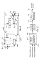
- In order that the invention may be more readily understood, it will now be described, by way of example only, with reference to Figures 4, 5 and 6 of the accompanying drawings, in which:-
- Figure 4 is a diagram showing one embodiment of the invention,
- Figure 5 is block diagram showing the internal structure of an ignition angle phase comparison controller shown in Figure 4, and
- Figure 6 is a flow chart showing the operation of the secondary arc extinction device of this invention.
- In Figure 4, reference LINE represents one conductor of a two conductor per phase multiphase transmission line. Each conductor is connected through a circuit breaker at each end to a bus bar BUS. L1 - L6 are reactors which are connected one to each of respective conductors of the tranmsission line and corresponding ends of the reactors are connected together. The primary winding of a step-down transformer TR is connected between the common point and ground. A neutral point reactor Lg and a thyristor assembly THY are connected in series.with the secondary winding of this transformer TR. The reactance (admittance) of the neutral point reactor L is continuously variable by controlling the ignition angle of the thyristyor assenbly THY. PRO is a protective relay into which inputs are provided from a current transformer CTl provided in the transmission line and the voltage from a potential transformer PD1 connected to the bus bar. This protective relay PRO is actuated when it detects a fault in the transmission line and delivers a trip pulse TP to the appropriate circuit breaker CB. CONT is an ignition angle controller which commences to operate when it receives an actuation output from the protective relay PRO and to which inputs are received from a potential transformer PD2 connected to the conductor of the transmission line and from a current transformer CT2 provided in the secondary circuit of the transformer TR. When its operation is started by means of the actuation output of the protective relay PRO, this ignition angle controller CONT converts the voltage and current signals which are inputted from the potential transformer PD2 and the current transformer CT2 into a DC level, and the ignition angle of the thyristor assembly THY is controlled by ascertaining this level. The thyristor assembly THY comprises two thyristors connected in anti-parallel relation.
- Referring to Figure 5, the ignition angle controller CONT is shown in block form. PHC is an ignition phase comparison controller to which are imputted as a start command the actuation of the protective relay PRO and through an analog/digital converter A/D the output of the potential transformer PD2 and the output of the current transformer CT2. This phase comparison controller PHC is in the form of a discriminator which contains a memory device such as a central processing unit CPU.
- PC is a phase control circuit to which is applied the output obtained through.a digital/analog converter D/A which is provided in the output stage of the ignition phase comparison controller PHC. PG is a pulse generator to which is applied the output α S of this phase control circuit PC and which supplies a gate signal GS to the thyristor assembly THY.
- The operation of the secondary arc extinguisher as described above will now be explained.
- Referring to Figure 4, when a fault occurs on one of the conductors of the transmission line, the transmission line protecting relay PRO detects the fault occurrence, fault phase and fault mode (
box 101 in Figure 6) and supplies this information as a digital signal to the ignition phase comparison controller PHC of the ignition angle controller CONT shown in Figure 5. This ignition phase comparison controller PHC applies an analog output corresponding to the fault to the phase control circuit PC. The circuit PC converts the level of the analog quantity into a voltage level corresponding to the ignition angle a and supplies this to the pulse generator PG. A generator sends the gate pulses that are necessary for thyristor ignition at the phase of the ignition angle α so that, in the first instance, the reactance of the neutral point reactor Lg is controlled to the value calculated as optimum for secondary arc extinction (box 102). - Now, in some cases, as mentioned earlier, due to errors in the determination of the transmission line constant, or to weather conditions, the secondary arc may not be extinguished. The arc voltage is, therefore, detected by the potential transformer PD2 connected to the transmission line and sent to the ignition angle phase comparator PHC which is provided with a discriminator such as a CPU in the form of a high speed analog signal obtained by the A/D converter.
- The neutral point reactor current (box 104) detected by the current transformer CT2 is cdnverted to a high speed digital signal by the A/D converter and sent to the ignition .phase comparison controller PHC.
- After the controller PHC has outputted a gate signal to the thyristor assembly THY, both the arc' voltage detection signal and the neutral point reactor current detected signal are inputted and stored to the controller PHC. When the output I0 of the current transformer CT2 exists, in other words, when the output . I0 is not zero, the voltage V0 from PD2 is compared with a previous value of voltage V0 which was detected when the fault occurred. As a result of the comparison, the ignition angle phase controller carries out a control operation whereby it delivers an output of a level which is lower or higher than the analog level which was produced before. This analog quantity is converted to an ignition angle ql by the phase circuit PC and the gate control is carried out by the pulse generator PG to alter the reactance of the neutral point reactor Lg by an amount ΔL. The secondary arc voltage is thereby altered by an amount ΔV
- When the reactance of the neutral point reactor Lg is altered by an amount Δ L, the new arc voltage level which is subsequently inputted to the analog/digital converter A/D is compared with the previous voltage level and, if the voltage level is lower, the ignition angle controller PHC outputs an analog level signal that is even lower (or even higher) than the digital analog converter D/A (box 115).
- On the other hand, if the new arc voltage level is higher than the preceding arc voltage level, then the ignition angle controller PHC outputs an analog level signal that is ΔV higher (or lower) than the analog level that was outputted previously (box 114). The reactance of the neutral point reactor L is, therefore, changed by ΔL.
- This process is repeated, changing the angle of ignition while applying a feedback such that the secondary arc voltage is a minimum and changing the reactance of the neutral point reactor L9 while comparing with the previous arc voltage. Soon as the secondary arc voltage reaches zero, or its minimum, whereupon this arc voltage changes considerably (box 111) and the current level of the neutral point reactor L9 becomes zero. The secondary arc is thus extinguished (box 112) and reclosing of the transmission line becomes possible.
- The above explanation concerns the case of an independent secondary arc extinguisher. However, with the high voltage transmission lines of recent years, the same object can be achieved by providing the said device at the neutral point of the reactor portion of the reactive power compensator that is connected to the transmission line for transmission stabilisation.
- As explained, above, according to this invention, there is provided a secondary arc extinguisher for high voltage, high capacity transmission lines whereby, whatever the conditions (including errors in the transmission line constant), control can be achieved to a mutual admittance which is optimum for secondary arc extinction, ensuring secondary arc extinction in a short time and making the period of time during which the conductor is disconnected from the supply much shorter and this is advantageous in electrical power systems.
- Thus, although the invention has been explained by way of example of one unit control for controlling the neutral point reactor TR-L , it should be apparent that phase control for individually controlling phase reactors L1 - L6 could be employed.
- That is to say, the transformer TR is replaced by a fixed neutral point reactor L g and a variable reactance device including the transformer TR, a reactor, the thyristor assembly THY, and current transformer CT2 is respectively connected between the line LINE and the fixed neutral point reactor L , instead of each phase reactor L1 - L 6.
- Potential transformers PD2 connected to each phase is connected with respective ignition angle controllers CONT.
Claims (4)
Applications Claiming Priority (2)
| Application Number | Priority Date | Filing Date | Title |
|---|---|---|---|
| JP86486/81 | 1981-06-05 | ||
| JP56086486A JPS57202824A (en) | 1981-06-05 | 1981-06-05 | Secondary arc extinguishing device for power system |
Publications (3)
| Publication Number | Publication Date |
|---|---|
| EP0067620A2 true EP0067620A2 (en) | 1982-12-22 |
| EP0067620A3 EP0067620A3 (en) | 1983-01-26 |
| EP0067620B1 EP0067620B1 (en) | 1986-02-12 |
Family
ID=13888305
Family Applications (1)
| Application Number | Title | Priority Date | Filing Date |
|---|---|---|---|
| EP82302840A Expired EP0067620B1 (en) | 1981-06-05 | 1982-06-02 | Secondary arc extinction device |
Country Status (4)
| Country | Link |
|---|---|
| US (1) | US4471401A (en) |
| EP (1) | EP0067620B1 (en) |
| JP (1) | JPS57202824A (en) |
| DE (1) | DE3269052D1 (en) |
Families Citing this family (4)
| Publication number | Priority date | Publication date | Assignee | Title |
|---|---|---|---|---|
| US7128148B2 (en) * | 2004-04-16 | 2006-10-31 | Halliburton Energy Services, Inc. | Well treatment fluid and methods for blocking permeability of a subterranean zone |
| CN100405686C (en) * | 2004-07-08 | 2008-07-23 | 思源电气股份有限公司 | Combined automatic tracing arc extinction compensation and line selecting device |
| ITTO20110722A1 (en) * | 2011-08-03 | 2013-02-04 | Microelettrica Scientifica Spa | DEVICE OF EMULATOR OF VARIABLE IMPEDANCE, AND SYSTEM OF CONTROL AND REGULATION OF THE STATE OF NEUTRAL IN A THREE-PHASE SYSTEM, INCLUDING SUCH A DEVICE |
| CN103048567B (en) * | 2012-12-21 | 2014-12-31 | 浙江大学 | Method for judging parallel reactor-containing transmission line malfunction properties based on wave form estimation |
Family Cites Families (9)
| Publication number | Priority date | Publication date | Assignee | Title |
|---|---|---|---|---|
| NL27336C (en) * | 1928-04-19 | |||
| US2050082A (en) * | 1935-12-12 | 1936-08-04 | Gen Electric | Suppression of ground faults on alternating current systems |
| US2824978A (en) * | 1953-11-09 | 1958-02-25 | Asea Ab | Arrangement for polyphase networks provided with means for high speed reclosing |
| GB1230830A (en) * | 1968-11-28 | 1971-05-05 | ||
| SE378719B (en) * | 1973-12-13 | 1975-09-08 | Asea Ab | |
| DE2710625C3 (en) * | 1977-03-11 | 1981-02-12 | Licentia Patent-Verwaltungs-Gmbh, 6000 Frankfurt | , Short-circuit protection device for a high-performance electrical system |
| SU807444A2 (en) * | 1979-04-27 | 1981-02-23 | Донецкий Ордена Трудового Красногознамени Политехнический Институт | Device for automatic adjusting of compensation current in the mode of alternating single-phase earthing |
| JPS5611523A (en) * | 1979-07-06 | 1981-02-04 | Nissin Electric Co Ltd | Suppressing unit for voltage variance |
| EP0026260B1 (en) * | 1979-09-27 | 1984-03-28 | Siemens Aktiengesellschaft | Device for controlling the voltage between two conductors of an a.c. supply mains for a rapidly changing load |
-
1981
- 1981-06-05 JP JP56086486A patent/JPS57202824A/en active Granted
-
1982
- 1982-06-02 EP EP82302840A patent/EP0067620B1/en not_active Expired
- 1982-06-02 DE DE8282302840T patent/DE3269052D1/en not_active Expired
- 1982-06-07 US US06/386,018 patent/US4471401A/en not_active Expired - Lifetime
Also Published As
| Publication number | Publication date |
|---|---|
| EP0067620A3 (en) | 1983-01-26 |
| JPS57202824A (en) | 1982-12-11 |
| DE3269052D1 (en) | 1986-03-27 |
| JPH0152973B2 (en) | 1989-11-10 |
| EP0067620B1 (en) | 1986-02-12 |
| US4471401A (en) | 1984-09-11 |
Similar Documents
| Publication | Publication Date | Title |
|---|---|---|
| US5699219A (en) | Ground fault current limiter and method of limiting ground fault current | |
| US4477855A (en) | Protecting system for transmission lines | |
| US4600961A (en) | Protective relay apparatus for detecting high-impedance ground faults | |
| EP1014530B1 (en) | Electrical power distribution installation for electrical power system | |
| CA1038450A (en) | Reactance controller | |
| US4631622A (en) | Multiple static trip circuit breaker coordination | |
| CN1127573A (en) | Method and device for limiting short-circuit current on power transmission lines | |
| EP0067620B1 (en) | Secondary arc extinction device | |
| EP0067563B1 (en) | Secondary arc extinction device | |
| US4479084A (en) | Secondary arc extinction device | |
| EP0067532A1 (en) | Secondary arc extinction device | |
| RU2009593C1 (en) | Device for protecting three-phase motors | |
| SU1030911A1 (en) | Device for power transmission to three-phase loads in isolated neutral system | |
| US2272991A (en) | Protective system | |
| US2951981A (en) | Capacitor bank | |
| US3383562A (en) | Electirical distribution system | |
| US3325686A (en) | Relay protective means for d.c. transmission | |
| SU1700624A1 (en) | Device for protection of transformer connected to power line through insulating switch | |
| JPH0224101B2 (en) | ||
| RU1836774C (en) | Internal surge and ferroresonance process limiting arrangement for systems with compensated capacitive fault-to earth current | |
| SU1647755A1 (en) | Method for compensating faulty phase potential | |
| SU655019A1 (en) | Arrangement for power supply of consumers | |
| SU1372471A1 (en) | A.c. power transmission | |
| SU966806A1 (en) | Method of phasewise automatic reconnection of generator-transformer-line block | |
| SU920956A1 (en) | Device for distributing electric power with ac |
Legal Events
| Date | Code | Title | Description |
|---|---|---|---|
| PUAI | Public reference made under article 153(3) epc to a published international application that has entered the european phase |
Free format text: ORIGINAL CODE: 0009012 |
|
| PUAL | Search report despatched |
Free format text: ORIGINAL CODE: 0009013 |
|
| AK | Designated contracting states |
Designated state(s): CH DE GB LI SE |
|
| AK | Designated contracting states |
Designated state(s): CH DE GB LI SE |
|
| 17P | Request for examination filed |
Effective date: 19830707 |
|
| RAP1 | Party data changed (applicant data changed or rights of an application transferred) |
Owner name: KABUSHIKI KAISHA TOSHIBA |
|
| GRAA | (expected) grant |
Free format text: ORIGINAL CODE: 0009210 |
|
| AK | Designated contracting states |
Designated state(s): CH DE GB LI SE |
|
| REF | Corresponds to: |
Ref document number: 3269052 Country of ref document: DE Date of ref document: 19860327 |
|
| PLBE | No opposition filed within time limit |
Free format text: ORIGINAL CODE: 0009261 |
|
| STAA | Information on the status of an ep patent application or granted ep patent |
Free format text: STATUS: NO OPPOSITION FILED WITHIN TIME LIMIT |
|
| REG | Reference to a national code |
Ref country code: GB Ref legal event code: 746 |
|
| 26N | No opposition filed | ||
| EAL | Se: european patent in force in sweden |
Ref document number: 82302840.2 |
|
| PGFP | Annual fee paid to national office [announced via postgrant information from national office to epo] |
Ref country code: SE Payment date: 19990414 Year of fee payment: 18 |
|
| PGFP | Annual fee paid to national office [announced via postgrant information from national office to epo] |
Ref country code: GB Payment date: 19990602 Year of fee payment: 18 |
|
| PGFP | Annual fee paid to national office [announced via postgrant information from national office to epo] |
Ref country code: DE Payment date: 19990607 Year of fee payment: 18 |
|
| PGFP | Annual fee paid to national office [announced via postgrant information from national office to epo] |
Ref country code: CH Payment date: 19990614 Year of fee payment: 18 |
|
| PG25 | Lapsed in a contracting state [announced via postgrant information from national office to epo] |
Ref country code: GB Free format text: LAPSE BECAUSE OF NON-PAYMENT OF DUE FEES Effective date: 20000602 |
|
| PG25 | Lapsed in a contracting state [announced via postgrant information from national office to epo] |
Ref country code: SE Free format text: LAPSE BECAUSE OF NON-PAYMENT OF DUE FEES Effective date: 20000603 |
|
| PG25 | Lapsed in a contracting state [announced via postgrant information from national office to epo] |
Ref country code: LI Free format text: LAPSE BECAUSE OF NON-PAYMENT OF DUE FEES Effective date: 20000630 Ref country code: CH Free format text: LAPSE BECAUSE OF NON-PAYMENT OF DUE FEES Effective date: 20000630 |
|
| GBPC | Gb: european patent ceased through non-payment of renewal fee |
Effective date: 20000602 |
|
| REG | Reference to a national code |
Ref country code: CH Ref legal event code: PL |
|
| EUG | Se: european patent has lapsed |
Ref document number: 82302840.2 |
|
| PG25 | Lapsed in a contracting state [announced via postgrant information from national office to epo] |
Ref country code: DE Free format text: LAPSE BECAUSE OF NON-PAYMENT OF DUE FEES Effective date: 20010403 |