EP0067640A2 - Böden - Google Patents
Böden Download PDFInfo
- Publication number
- EP0067640A2 EP0067640A2 EP82302928A EP82302928A EP0067640A2 EP 0067640 A2 EP0067640 A2 EP 0067640A2 EP 82302928 A EP82302928 A EP 82302928A EP 82302928 A EP82302928 A EP 82302928A EP 0067640 A2 EP0067640 A2 EP 0067640A2
- Authority
- EP
- European Patent Office
- Prior art keywords
- panels
- floor
- adjacent
- locating
- skating
- Prior art date
- Legal status (The legal status is an assumption and is not a legal conclusion. Google has not performed a legal analysis and makes no representation as to the accuracy of the status listed.)
- Granted
Links
Images


Classifications
-
- F—MECHANICAL ENGINEERING; LIGHTING; HEATING; WEAPONS; BLASTING
- F16—ENGINEERING ELEMENTS AND UNITS; GENERAL MEASURES FOR PRODUCING AND MAINTAINING EFFECTIVE FUNCTIONING OF MACHINES OR INSTALLATIONS; THERMAL INSULATION IN GENERAL
- F16B—DEVICES FOR FASTENING OR SECURING CONSTRUCTIONAL ELEMENTS OR MACHINE PARTS TOGETHER, e.g. NAILS, BOLTS, CIRCLIPS, CLAMPS, CLIPS OR WEDGES; JOINTS OR JOINTING
- F16B5/00—Joining sheets or plates, e.g. panels, to one another or to strips or bars parallel to them
- F16B5/0004—Joining sheets, plates or panels in abutting relationship
- F16B5/0056—Joining sheets, plates or panels in abutting relationship by moving the sheets, plates or panels or the interlocking key perpendicular to the main plane
- F16B5/0068—Joining sheets, plates or panels in abutting relationship by moving the sheets, plates or panels or the interlocking key perpendicular to the main plane and using I-shaped clamps with flanges moving towards each other
-
- E—FIXED CONSTRUCTIONS
- E01—CONSTRUCTION OF ROADS, RAILWAYS, OR BRIDGES
- E01C—CONSTRUCTION OF, OR SURFACES FOR, ROADS, SPORTS GROUNDS, OR THE LIKE; MACHINES OR AUXILIARY TOOLS FOR CONSTRUCTION OR REPAIR
- E01C13/00—Pavings or foundations specially adapted for playgrounds or sports grounds; Drainage, irrigation or heating of sports grounds
- E01C13/003—Construction of, or surfacings for, rinks or tracks for roller skating, skate-boarding or the like
-
- E—FIXED CONSTRUCTIONS
- E01—CONSTRUCTION OF ROADS, RAILWAYS, OR BRIDGES
- E01C—CONSTRUCTION OF, OR SURFACES FOR, ROADS, SPORTS GROUNDS, OR THE LIKE; MACHINES OR AUXILIARY TOOLS FOR CONSTRUCTION OR REPAIR
- E01C13/00—Pavings or foundations specially adapted for playgrounds or sports grounds; Drainage, irrigation or heating of sports grounds
- E01C13/10—Pavings or foundations specially adapted for playgrounds or sports grounds; Drainage, irrigation or heating of sports grounds for artificial surfaces for outdoor or indoor practice of snow or ice sports
- E01C13/107—Non-frozen surfacings for ice, skating or curling rinks or for sledge runs; Rinks or runs with such surfacings
-
- E—FIXED CONSTRUCTIONS
- E01—CONSTRUCTION OF ROADS, RAILWAYS, OR BRIDGES
- E01C—CONSTRUCTION OF, OR SURFACES FOR, ROADS, SPORTS GROUNDS, OR THE LIKE; MACHINES OR AUXILIARY TOOLS FOR CONSTRUCTION OR REPAIR
- E01C5/00—Pavings made of prefabricated single units
- E01C5/005—Individual couplings or spacer elements for joining the prefabricated units
-
- E—FIXED CONSTRUCTIONS
- E04—BUILDING
- E04B—GENERAL BUILDING CONSTRUCTIONS; WALLS, e.g. PARTITIONS; ROOFS; FLOORS; CEILINGS; INSULATION OR OTHER PROTECTION OF BUILDINGS
- E04B1/00—Constructions in general; Structures which are not restricted either to walls, e.g. partitions, or floors or ceilings or roofs
- E04B1/38—Connections for building structures in general
- E04B1/61—Connections for building structures in general of slab-shaped building elements with each other
- E04B1/6108—Connections for building structures in general of slab-shaped building elements with each other the frontal surfaces of the slabs connected together
- E04B1/612—Connections for building structures in general of slab-shaped building elements with each other the frontal surfaces of the slabs connected together by means between frontal surfaces
- E04B1/6166—Connections for building structures in general of slab-shaped building elements with each other the frontal surfaces of the slabs connected together by means between frontal surfaces with protrusions on both frontal surfaces
- E04B1/617—Connections for building structures in general of slab-shaped building elements with each other the frontal surfaces of the slabs connected together by means between frontal surfaces with protrusions on both frontal surfaces with one protrusion on each frontal surface
-
- E—FIXED CONSTRUCTIONS
- E04—BUILDING
- E04F—FINISHING WORK ON BUILDINGS, e.g. STAIRS, FLOORS
- E04F15/00—Flooring
- E04F15/02—Flooring or floor layers composed of a number of similar elements
-
- E—FIXED CONSTRUCTIONS
- E04—BUILDING
- E04F—FINISHING WORK ON BUILDINGS, e.g. STAIRS, FLOORS
- E04F15/00—Flooring
- E04F15/02—Flooring or floor layers composed of a number of similar elements
- E04F15/10—Flooring or floor layers composed of a number of similar elements of other materials, e.g. fibrous or chipped materials, organic plastics, magnesite tiles, hardboard, or with a top layer of other materials
-
- Y—GENERAL TAGGING OF NEW TECHNOLOGICAL DEVELOPMENTS; GENERAL TAGGING OF CROSS-SECTIONAL TECHNOLOGIES SPANNING OVER SEVERAL SECTIONS OF THE IPC; TECHNICAL SUBJECTS COVERED BY FORMER USPC CROSS-REFERENCE ART COLLECTIONS [XRACs] AND DIGESTS
- Y10—TECHNICAL SUBJECTS COVERED BY FORMER USPC
- Y10T—TECHNICAL SUBJECTS COVERED BY FORMER US CLASSIFICATION
- Y10T403/00—Joints and connections
- Y10T403/75—Joints and connections having a joining piece extending through aligned openings in plural members
Definitions
- the invention relates to floors, for example for use as ice or roller skating floors.
- the invention provides a floor for use as an ice or roller skating floor, comprising a plurality of panels arrangeable to provide a substantially continuous planar surface, and a plurality of locating devices arrangeable between each pair of adjacent panels, each locating device having a portion which overlies the adjacent parts of the two panels of thepair, in such a manner as to restrict upward movement of one panel with respect to the other panel.
- the locating device also has a portion which underlies adjacent parts of the two panels, so that the adjacent edges of the two panels are sandwiched between the two portions of the locating device.
- the locating device hooks over a part of each of the two panels so that the two panels are prevented from moving apart in the horizontal direction.
- the locating device preferably comprises upper and lower portions which are threadedly connectable together to sandwich the panels therebetween.
- One of the parts may have a tapered interengagement with the panels so that as the parts are threaded together to sandwich the panels therebetween, adjacent panels are urged towards one another.
- the upper portion may have a female screw thread, the lower portion having a male screw thread, the male screw thread being accessible through the upper portion so that both the portions can be gripped from above the floor for screwing the portions together.
- the locating device may be arranged to hook over the panels by virtue of a flange on one of the portions which seats in a groove provided in the panels.
- the panels are manufactured from high molecular weight polyethylene.
- the upper portion of the locating device is also preferably manufactured from this material.
- the lower portion of the locating-device may be manufactured from this material or from some other material such as metal.
- the thickness of the floor may be in the range 15 mm to 25 mm, for example 20 mm.
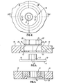
- Figure 1 shows a plurality of substantially square panels 10 arranged in a staggered formation to provide a substantially continuous floor.
- the panels are made of high molecular weight polyethylene which provides a surface which has been found to be effective as a substitute for ice when ice skating.
- each edge of each panel is machined at two locations 11 to provide a circular cross-section (when viewed in plan view) locating device 12.
- each locating-device fastens together the mating edges of each pair of adjacent panels, both in the upward direction and the horizontal direction, thus providing a firm secure floor with minimal risk of any one panel riding up and providing an obstruction to a skater.
- each locating device 12 comprises an upper portion in the form of a nut 13 and a lower portion in the form of a bolt 14.
- the underside of the panels 10 are machined away at 15 to receive the head of the bolt, there is an aperture 16 through which the shank 17 of the bolt can pass, and the upper face of the panels 10 is machined away at 18 to receive the nut 13.
- Each of the panels 10 has sufficient space to accommodate half of the bolt and half of the nut, so that when the panels are fitted together as shown in Figure 1, the panels combine to form spaces each of which can accommodate a whole bolt and a whole nut.
- Each bolt 14 has an upwardly extending peripheral flange 19 and each panel is provided with an arcuate groove 20 into which this flange 19 can hook.
- Each bolt is provided with a square section bore 21 and each nut 13 is provided with a pair of holes 22.
- each bolt 14 is positioned underneath each of the locations 11. This can be done very rapidly, the bolts fitting neatly into position with their flanges 19 engaging-in the grooves 20.
- the bolts can then be held against rotation from above the floor by inserting an appropriate key into the bore 21, and each bolt can have a nut 13 screwed on to it by inserting an appropriate key, for example a C-shaped spanner having pegs that project into the holes 22.
- each nut is screwed tightly down on to the associated bolt, the locating device is as shown in Figure 3.
- the upper face of the nut, together with the upper end of the shank of the bolt, combine with the panels 10 to provide a smooth continuous surface. Since each nut overlies part of each pair of adjacent panels, each edge of each panel is prevented from rising with respect to the adjacent panel. Furthermore, because the flanges 19 hook into the grooves 20, the panels are also prevented from moving with respect to one another in the horizontal direction.
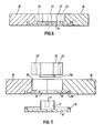
- Figure 5 illustrates an embodiment which is generally similar, except for the fact that the head of the bolt 14 is smaller, the nut 13 is larger, and instead of providing a flange 19 on the head of the bolt, a flange 23 is provided on the nut.
- Figures 6 and 7 show an embodiment generally similar to that shown in Figures 1 to 4, except that the nut 13 has a downwardly projecting boss 13a thereon.
- the hole 16 and bolt shank 17 are of such a size that the shank 17 can pass through the hole 16 with clearance around the shank. When the nut is tightened, this clearance is filled by the boss 13a, as best illustrated in Figure 6.
- this embodiment also utilises substantially square panels of high molecular weight polyethylene, one panel 24 being shown in plan view in Figure 8 and two panels 24 being shown joined together in Figure 9.
- notches 25 are provided in the edges of the panels, at the corners of the panels, and when panels are assembled together as shown in Figure 9 the notches co-operate to define a plurality of bores, one of which is shown at 26 in Figure 9, the bores extending vertically through the skating surface from the lower face 30 of the skating surface to the upper face 31.
- an upper rebate 32 is provided around each notch and when the panels are assembled these rebates co-operate to define an upper counterbore 33 (see Figure 9) at the upper end of each bore 29.
- each rebate in the lower face of each panel, again surrounding each notch 25, these rebates co-operating to define a lower counterbore 34 at the lower end of each bore 29.
- the counterbore 34 has a greater diameter than the counterbore 33 but is much lower in height, as clearly shown in Figure 9.
- each lower rebate in the lower face of each panel Surrounding each lower rebate in the lower face of each panel is an arcuate groove 35 so that when the panels are assembled the grooves 35 co-operate to define a circular groove extending around the periphery of.the lower counterbore 34.
- each member 36 comprises a disc-like plate 37 from which projects an internally screw-threaded boss 38 and a peripheral flange 39.
- the boss 38 projects into-the bore 29 and the flange 39 mates with the grooves 35.
- the upper face 40 of the plate is knurled or otherwise roughened to increase friction with the surface 41 of the panels and reduce any tendency for the member 36 to rotate.
- a second locating member in the form of a cylindrical plug 42 having an externally threaded boss 43a which is screwed into the internally threaded boss 38 of the lower member 36.
- the plug 42 can be rotated with an appropriate tool engaging in two sockets 43 in the upper face of the plug, the lower member 36 being held against rotation because of the frictional engagement between the surfaces 40 and 41.
- the two locating members securely sandwich between them the corners of four panels, so that none of,the corners can lift with respect to any of the other corners.
- the panels are held together against movement in the horizontal'direction by engagement of the flanges 39 in the grooves 35.
- the flanges 39 and grooves 35 have tapered co-operating surfaces 44 and 45 so that any gaps between the edges of the panels tend to be closed since the panels are drawn together in the horizontal direction as the flanges 39 move into the grooves 35.
- the invention is not restricted to the details of the foregoing embodiments.
- the bolts, and/or the nuts may be manufactured wholly or partly from metal.
- the panels may have other configurations. They may for example be rectangular, and a preferred size has the dimensions 1.2 metres x 0.6 metres. A panel of such dimensions may for example be held in position by a total of ten locating devices, there being four on each of the two long sides of the panel and two on each of the two short sides of the panel.
Landscapes
- Engineering & Computer Science (AREA)
- Architecture (AREA)
- Civil Engineering (AREA)
- Structural Engineering (AREA)
- General Engineering & Computer Science (AREA)
- Mechanical Engineering (AREA)
- Physics & Mathematics (AREA)
- Electromagnetism (AREA)
- Floor Finish (AREA)
- Air-Conditioning For Vehicles (AREA)
Priority Applications (1)
| Application Number | Priority Date | Filing Date | Title |
|---|---|---|---|
| AT82302928T ATE33282T1 (de) | 1981-06-17 | 1982-06-08 | Boeden. |
Applications Claiming Priority (2)
| Application Number | Priority Date | Filing Date | Title |
|---|---|---|---|
| GB8118563 | 1981-06-17 | ||
| GB8118563 | 1981-06-17 |
Publications (3)
| Publication Number | Publication Date |
|---|---|
| EP0067640A2 true EP0067640A2 (de) | 1982-12-22 |
| EP0067640A3 EP0067640A3 (en) | 1983-11-02 |
| EP0067640B1 EP0067640B1 (de) | 1988-03-30 |
Family
ID=10522556
Family Applications (1)
| Application Number | Title | Priority Date | Filing Date |
|---|---|---|---|
| EP82302928A Expired EP0067640B1 (de) | 1981-06-17 | 1982-06-08 | Böden |
Country Status (4)
| Country | Link |
|---|---|
| US (1) | US4577448A (de) |
| EP (1) | EP0067640B1 (de) |
| AT (1) | ATE33282T1 (de) |
| DE (1) | DE3278286D1 (de) |
Cited By (8)
| Publication number | Priority date | Publication date | Assignee | Title |
|---|---|---|---|---|
| FR2612972A1 (fr) * | 1986-11-05 | 1988-09-30 | Tmh Taasiat Mishmar Ha Emek | Panneau de plancher |
| WO1988010339A1 (en) * | 1987-06-16 | 1988-12-29 | Smp (Playgrounds) Limited | Tiles for playground surfaces |
| EP0335110A3 (de) * | 1988-03-30 | 1991-04-17 | Josef Wund | Einrichtung zur unterschiedlichen Nutzbarkeit einer mit einem Rasenbelag oder einem ähnlichen Belag versehenen Fläche |
| NL1033722C2 (nl) * | 2007-04-19 | 2008-10-21 | Zoontjens Beton B V | Tegelsamenstel met een profiellichaam met zich verjongende kamers. |
| WO2009153044A1 (de) * | 2008-06-18 | 2009-12-23 | Ralf Gross | Verfahren zur trocknung und optischen wiederherstellung von bodenbelägen nach wassereinbruch |
| WO2014184325A1 (en) * | 2013-05-15 | 2014-11-20 | Philip Mcintosh | A modular ramp system |
| EP2108072B1 (de) * | 2007-02-02 | 2017-06-14 | Gio'Speedy Di Giovanni Iovene | System zur vorübergehenden befestigung von holzblöcken für holzböden oder ähnliches |
| CN109252436A (zh) * | 2018-09-21 | 2019-01-22 | 王俊铎 | 一种便于快速安装的地砖结构 |
Families Citing this family (72)
| Publication number | Priority date | Publication date | Assignee | Title |
|---|---|---|---|---|
| DE8427790U1 (de) * | 1984-09-21 | 1985-01-31 | Berleburger Schaumstoffwerk Gmbh, 5920 Bad Berleburg | Fahrdynamische Schwelle für Kraftverkehrswege |
| US4693629A (en) * | 1985-11-25 | 1987-09-15 | Datron Systems, Inc. | Fastener for joining panels to each other |
| US4720115A (en) * | 1986-05-02 | 1988-01-19 | Houston Rehrig | Plastic dolly |
| US5102256A (en) * | 1988-11-07 | 1992-04-07 | Gosnell Glenn D | Containment system for paving material |
| KR900702141A (ko) * | 1988-11-07 | 1990-12-05 | 디. 고스넬 글렌 | 포장 재료용 밀봉 시스템 |
| US5281055C1 (en) * | 1992-07-17 | 2001-08-14 | Marine Floats Inc | Floating dock |
| WO1994018392A1 (en) * | 1993-02-04 | 1994-08-18 | Viscount Plastics Pty. Ltd. | A device for fastening elements together |
| JPH1161719A (ja) * | 1997-08-19 | 1999-03-05 | Miyagawa Kasei Ind Co Ltd | 敷板の連結構造 |
| US6061979A (en) * | 1997-09-30 | 2000-05-16 | Johannes; Nicholas J. | Inline skating sports floor |
| US6210069B1 (en) * | 1998-04-27 | 2001-04-03 | John W. Speck | Support block for use in interconnecting storage crates, and method of using same |
| WO2000074544A1 (en) | 1999-06-07 | 2000-12-14 | Tac-Fast Systems S.A. | Anchor sheet attachment devices |
| JP3855124B2 (ja) * | 1999-07-02 | 2006-12-06 | エクセレント システムズ エー/エス | 傾斜構造およびそのための部品 |
| US6247282B1 (en) * | 1999-10-28 | 2001-06-19 | Icon, Incorporated | Deck and beam connector |
| US7614197B2 (en) * | 1999-11-08 | 2009-11-10 | Premark Rwp Holdings, Inc. | Laminate flooring |
| US7833250B2 (en) | 2004-11-10 | 2010-11-16 | Jackson Roger P | Polyaxial bone screw with helically wound capture connection |
| US6726687B2 (en) * | 2000-12-08 | 2004-04-27 | Jackson Roger P | Closure plug for open-headed medical implant |
| US8377100B2 (en) * | 2000-12-08 | 2013-02-19 | Roger P. Jackson | Closure for open-headed medical implant |
| US6726689B2 (en) * | 2002-09-06 | 2004-04-27 | Roger P. Jackson | Helical interlocking mating guide and advancement structure |
| US7412806B2 (en) * | 2001-12-13 | 2008-08-19 | Tac-Fast Georgia Llc | Structures for creating spaces while installing anchor sheet and attachment piece subfloors |
| EP1461505A4 (de) * | 2002-01-07 | 2005-01-19 | Collins & Aikman Automotive Co | Verbindungsanordnung für ein verkleidungsteil |
| US8876868B2 (en) * | 2002-09-06 | 2014-11-04 | Roger P. Jackson | Helical guide and advancement flange with radially loaded lip |
| US8282673B2 (en) * | 2002-09-06 | 2012-10-09 | Jackson Roger P | Anti-splay medical implant closure with multi-surface removal aperture |
| US8257402B2 (en) * | 2002-09-06 | 2012-09-04 | Jackson Roger P | Closure for rod receiving orthopedic implant having left handed thread removal |
| US20060009773A1 (en) * | 2002-09-06 | 2006-01-12 | Jackson Roger P | Helical interlocking mating guide and advancement structure |
| GB0221726D0 (en) * | 2002-09-19 | 2002-10-30 | Mccormack Lee C | Support system |
| PT1589856E (pt) * | 2003-01-30 | 2008-07-18 | Tac Fast Systems Sa | Sistema de posicionamento e de ligação com folha de fixação |
| US6716214B1 (en) * | 2003-06-18 | 2004-04-06 | Roger P. Jackson | Polyaxial bone screw with spline capture connection |
| US7377923B2 (en) | 2003-05-22 | 2008-05-27 | Alphatec Spine, Inc. | Variable angle spinal screw assembly |
| US8137386B2 (en) | 2003-08-28 | 2012-03-20 | Jackson Roger P | Polyaxial bone screw apparatus |
| US8398682B2 (en) | 2003-06-18 | 2013-03-19 | Roger P. Jackson | Polyaxial bone screw assembly |
| US8366753B2 (en) * | 2003-06-18 | 2013-02-05 | Jackson Roger P | Polyaxial bone screw assembly with fixed retaining structure |
| US7776067B2 (en) | 2005-05-27 | 2010-08-17 | Jackson Roger P | Polyaxial bone screw with shank articulation pressure insert and method |
| US8936623B2 (en) | 2003-06-18 | 2015-01-20 | Roger P. Jackson | Polyaxial bone screw assembly |
| US7766915B2 (en) | 2004-02-27 | 2010-08-03 | Jackson Roger P | Dynamic fixation assemblies with inner core and outer coil-like member |
| US7967850B2 (en) | 2003-06-18 | 2011-06-28 | Jackson Roger P | Polyaxial bone anchor with helical capture connection, insert and dual locking assembly |
| US7748177B2 (en) * | 2004-02-25 | 2010-07-06 | Connor Sport Court International, Inc. | Modular tile with controlled deflection |
| US8407951B2 (en) * | 2004-10-06 | 2013-04-02 | Connor Sport Court International, Llc | Modular synthetic floor tile configured for enhanced performance |
| US8397466B2 (en) * | 2004-10-06 | 2013-03-19 | Connor Sport Court International, Llc | Tile with multiple-level surface |
| US20090235605A1 (en) * | 2004-10-06 | 2009-09-24 | Thayne Haney | Method of Making A Modular Synthetic Floor Tile Configured For Enhanced Performance |
| US8926672B2 (en) | 2004-11-10 | 2015-01-06 | Roger P. Jackson | Splay control closure for open bone anchor |
| JP2008519656A (ja) | 2004-11-10 | 2008-06-12 | ロジャー・ピー・ジャクソン | 破断伸張部付の螺旋状案内及び前進フランジ |
| US9168069B2 (en) | 2009-06-15 | 2015-10-27 | Roger P. Jackson | Polyaxial bone anchor with pop-on shank and winged insert with lower skirt for engaging a friction fit retainer |
| US10076361B2 (en) | 2005-02-22 | 2018-09-18 | Roger P. Jackson | Polyaxial bone screw with spherical capture, compression and alignment and retention structures |
| US7694480B2 (en) * | 2005-06-27 | 2010-04-13 | Niese Michael W | Panel-type subfloor for athletic floor |
| US20070062131A1 (en) * | 2005-08-10 | 2007-03-22 | Yokubison Ronald A | Method and system for supporting sports-related components about a modular flooring system |
| US7914228B2 (en) * | 2006-05-17 | 2011-03-29 | Antonio Rapaz | Multi-purpose construction module |
| US8979904B2 (en) | 2007-05-01 | 2015-03-17 | Roger P Jackson | Connecting member with tensioned cord, low profile rigid sleeve and spacer with torsion control |
| US20090293397A1 (en) * | 2008-05-27 | 2009-12-03 | Lytton John L | Load-Transfer Device For Reinforcing Concrete Structures |
| US8118345B1 (en) * | 2009-03-27 | 2012-02-21 | Thomas David Hootman | Flooring system for use with flatbed trailers |
| US11229457B2 (en) | 2009-06-15 | 2022-01-25 | Roger P. Jackson | Pivotal bone anchor assembly with insert tool deployment |
| US8881482B2 (en) | 2010-01-22 | 2014-11-11 | Connor Sport Court International, Llc | Modular flooring system |
| US8683769B2 (en) * | 2010-01-22 | 2014-04-01 | Connor Sport Court International, Llc | Modular sub-flooring system |
| US8505256B2 (en) * | 2010-01-29 | 2013-08-13 | Connor Sport Court International, Llc | Synthetic floor tile having partially-compliant support structure |
| CA2774386A1 (en) | 2011-04-15 | 2012-10-15 | Tac-Fast Systems Canada Limited | Methods and systems for engagement of decorative covering |
| US8911479B2 (en) | 2012-01-10 | 2014-12-16 | Roger P. Jackson | Multi-start closures for open implants |
| US8911478B2 (en) | 2012-11-21 | 2014-12-16 | Roger P. Jackson | Splay control closure for open bone anchor |
| US10058354B2 (en) | 2013-01-28 | 2018-08-28 | Roger P. Jackson | Pivotal bone anchor assembly with frictional shank head seating surfaces |
| US8852239B2 (en) | 2013-02-15 | 2014-10-07 | Roger P Jackson | Sagittal angle screw with integral shank and receiver |
| US9566092B2 (en) | 2013-10-29 | 2017-02-14 | Roger P. Jackson | Cervical bone anchor with collet retainer and outer locking sleeve |
| US9717533B2 (en) | 2013-12-12 | 2017-08-01 | Roger P. Jackson | Bone anchor closure pivot-splay control flange form guide and advancement structure |
| US9451993B2 (en) | 2014-01-09 | 2016-09-27 | Roger P. Jackson | Bi-radial pop-on cervical bone anchor |
| US9597119B2 (en) | 2014-06-04 | 2017-03-21 | Roger P. Jackson | Polyaxial bone anchor with polymer sleeve |
| US10064658B2 (en) | 2014-06-04 | 2018-09-04 | Roger P. Jackson | Polyaxial bone anchor with insert guides |
| KR101646184B1 (ko) * | 2014-06-26 | 2016-08-08 | 스코트라 주식회사 | 중장비의 이동을 위한 폰툰 및 이를 위한 폰툰용 데크 |
| WO2016112402A2 (en) * | 2015-01-09 | 2016-07-14 | Malmquist M Casey | Pick mat locking system |
| KR101735527B1 (ko) | 2015-10-23 | 2017-05-15 | 재단법인한국조선해양기자재연구원 | 중장비의 이동을 위한 폰툰 및 이를 위한 폰툰용 데크 조립체 |
| ITUA20164281A1 (it) * | 2016-06-10 | 2017-12-10 | Eps Italia Srl | Pannelli modulari per la realizzazione di una pavimentazione temporanea calpestabile componibile/scomponibile e metodo per realizzare detta pavimentazione |
| US10246831B1 (en) | 2016-06-13 | 2019-04-02 | James Loughran | Synthetic ice panel |
| BE1024723B1 (nl) * | 2016-11-10 | 2018-06-11 | Ivc Bvba | Vloerpaneel en werkwijze voor het vervaardigen van een vloerpaneel. |
| TWM561114U (zh) * | 2017-09-06 | 2018-06-01 | 潤弘精密工程事業股份有限公司 | 格子板、用於格子板之回填塞及格子板回填結構 |
| USD970055S1 (en) | 2021-04-25 | 2022-11-15 | James Loughran | Modular floor panel locking system |
| US12279710B2 (en) * | 2021-07-09 | 2025-04-22 | Dorai Home, Inc. | Reconfigurable absorption mat |
Family Cites Families (30)
| Publication number | Priority date | Publication date | Assignee | Title |
|---|---|---|---|---|
| GB135881A (en) * | 1918-08-30 | 1919-12-01 | Emily Louisa Jane Le Breton | Improvements in Floors and Roofs. |
| CH107556A (de) * | 1924-02-27 | 1925-02-16 | Suter Strickler Heinrich | Strassenbelag mit aneinanderstossenden künstlichen Steinplatten. |
| US1888937A (en) * | 1928-04-06 | 1932-11-22 | Renault Louis | Metallic flooring and method of laying the same |
| US2341777A (en) * | 1942-04-13 | 1944-02-15 | Universal Oil Prod Co | Insulating block |
| US2453221A (en) * | 1944-07-21 | 1948-11-09 | Emile S Guignon Jr | Interlocking building units |
| FR61013E (fr) * | 1945-10-05 | 1955-03-23 | Procédé de construction pour l'établissement de surfaces de roulage | |
| US2867301A (en) * | 1956-07-26 | 1959-01-06 | Joseph H Benton | False flooring system |
| DE1811446U (de) * | 1959-08-06 | 1960-05-19 | Henschel Werke G M B H | Schraubenverbindung fuer bodenbelagplatten. |
| GB902259A (en) * | 1960-02-08 | 1962-08-01 | Kerridge Joinery Ltd | Improvements in or relating to portable floors |
| US3285633A (en) * | 1963-10-30 | 1966-11-15 | Dow Chemical Co | Fastener |
| US3310919A (en) * | 1964-10-02 | 1967-03-28 | Sico Inc | Portable floor |
| US3363382A (en) * | 1965-09-03 | 1968-01-16 | Dow Chemical Co | Meshing panels with interfitting expandable locking strips |
| NL6602434A (de) * | 1966-02-24 | 1967-08-25 | ||
| CH519067A (fr) * | 1970-11-03 | 1972-02-15 | Von Sury Charles | Faux-plancher |
| DE2116407A1 (de) * | 1971-04-03 | 1972-10-12 | Rheinstahl Ag, 4300 Essen | Fehlboden bzw Zwischendecke |
| US3778956A (en) * | 1971-05-12 | 1973-12-18 | R Martin | Glass pane fastening |
| DE2147032A1 (de) * | 1971-09-21 | 1973-03-29 | Geb Winkler Elisabeth Lohaus | Aus bodenplatten gebildeter umsetzbarer fehlboden |
| US3943674A (en) * | 1972-11-14 | 1976-03-16 | Liskey Aluminum Inc. | Elevated floor assembly with releasable tie means connecting the panel sides |
| US3903667A (en) * | 1973-06-18 | 1975-09-09 | Lev Zetlin Associates Inc | Structural floor system accomodating multi-directional ducts |
| US4074488A (en) * | 1974-06-05 | 1978-02-21 | Liskey Archectural Mfg. Inc. | Elevated floor assembly |
| GB1473143A (de) * | 1974-07-13 | 1977-05-11 | ||
| US4169688A (en) * | 1976-03-15 | 1979-10-02 | Sato Toshio | Artificial skating-rink floor |
| DE2723307A1 (de) * | 1977-05-24 | 1978-12-07 | All Seasons Recreation Inc | Kunsteisbahn |
| FR2446376A1 (fr) * | 1979-01-15 | 1980-08-08 | Pont A Mousson | Procede et dispositif pour l'assemblage de voussoirs d'un revetement de tunnel |
| DE2916482A1 (de) * | 1979-04-24 | 1980-12-04 | Terbrack Kunststoff Gmbh & Co | Platte mit verbindungsmitteln fuer eine zusammengesetzte spielflaeche, z.b. fuer schlittschuhlauf, kegeln, aehnliches |
| CH642701A5 (de) * | 1979-09-03 | 1984-04-30 | Willi Ruckstuhl | Fahrbahndecke aus einzelnen, miteinander verbundenen elementen. |
| US4435935A (en) * | 1980-10-08 | 1984-03-13 | Perfil En Frio, S.A. (Perfrisa) | Panel joining system |
| US4455798A (en) * | 1981-09-04 | 1984-06-26 | Wasco Products, Inc. | Skylight system |
| US4430837A (en) * | 1981-11-16 | 1984-02-14 | Bell Telephone Laboratories, Incorporated | Fastening arrangement for abutting structural members |
| US4440818A (en) * | 1983-03-30 | 1984-04-03 | Teknor Apex Company | Floor mat connector device |
-
1982
- 1982-06-03 US US06/384,743 patent/US4577448A/en not_active Expired - Fee Related
- 1982-06-08 DE DE8282302928T patent/DE3278286D1/de not_active Expired
- 1982-06-08 AT AT82302928T patent/ATE33282T1/de not_active IP Right Cessation
- 1982-06-08 EP EP82302928A patent/EP0067640B1/de not_active Expired
Cited By (9)
| Publication number | Priority date | Publication date | Assignee | Title |
|---|---|---|---|---|
| FR2612972A1 (fr) * | 1986-11-05 | 1988-09-30 | Tmh Taasiat Mishmar Ha Emek | Panneau de plancher |
| WO1988010339A1 (en) * | 1987-06-16 | 1988-12-29 | Smp (Playgrounds) Limited | Tiles for playground surfaces |
| EP0335110A3 (de) * | 1988-03-30 | 1991-04-17 | Josef Wund | Einrichtung zur unterschiedlichen Nutzbarkeit einer mit einem Rasenbelag oder einem ähnlichen Belag versehenen Fläche |
| EP2108072B1 (de) * | 2007-02-02 | 2017-06-14 | Gio'Speedy Di Giovanni Iovene | System zur vorübergehenden befestigung von holzblöcken für holzböden oder ähnliches |
| NL1033722C2 (nl) * | 2007-04-19 | 2008-10-21 | Zoontjens Beton B V | Tegelsamenstel met een profiellichaam met zich verjongende kamers. |
| WO2009153044A1 (de) * | 2008-06-18 | 2009-12-23 | Ralf Gross | Verfahren zur trocknung und optischen wiederherstellung von bodenbelägen nach wassereinbruch |
| WO2014184325A1 (en) * | 2013-05-15 | 2014-11-20 | Philip Mcintosh | A modular ramp system |
| US9441333B2 (en) | 2013-05-15 | 2016-09-13 | Philip McIntosh | Modular ramp system |
| CN109252436A (zh) * | 2018-09-21 | 2019-01-22 | 王俊铎 | 一种便于快速安装的地砖结构 |
Also Published As
| Publication number | Publication date |
|---|---|
| ATE33282T1 (de) | 1988-04-15 |
| EP0067640A3 (en) | 1983-11-02 |
| US4577448A (en) | 1986-03-25 |
| EP0067640B1 (de) | 1988-03-30 |
| DE3278286D1 (en) | 1988-05-05 |
Similar Documents
| Publication | Publication Date | Title |
|---|---|---|
| US4577448A (en) | Floors | |
| DE69726455T2 (de) | Schneideinsatz und halter für metallbearbeitung | |
| DE69417042T2 (de) | Doppelboden niedriger bauhöhe mit metalltragstruktur | |
| US2144350A (en) | Fastening means | |
| US4584221A (en) | Floor covering assembly | |
| US20170232499A1 (en) | Method of making composite deck clips | |
| US20170350141A1 (en) | Deck pedestal | |
| DE60200556T2 (de) | Werkzeugträger | |
| DE69822000T2 (de) | Wand der abnutzung ausgesetzt und abnutzungsbeständige verkleidung | |
| US4469466A (en) | Fastening device | |
| US9834927B2 (en) | Floor protector | |
| EP2654993B1 (de) | Schneideinsatz mit strukturierten freiflächen | |
| EP1335069B1 (de) | Kunststein für Pflasterzwecke | |
| US3967428A (en) | Portable floor construction | |
| DE3037508C2 (de) | ||
| WO1994018392A1 (en) | A device for fastening elements together | |
| DE112017007688T5 (de) | Bauplatte, vorzugsweise für eine Abdeckung im Inneren eines Gebäudes | |
| DE19653921B4 (de) | Schneidwerkzeugeinheit aus einem Werkzeughalter und einer Wendeschneidplatte | |
| CA2985906C (en) | Deck pedestal | |
| EP0619406B1 (de) | Klemmkeil zum Verlegen von Parkett-Dielen | |
| EP0289532A1 (de) | Elastischer gerätefuss. | |
| US4687366A (en) | Corner connecting arrangement | |
| CA2069698A1 (en) | Railroad grade crossings | |
| EP0623705B1 (de) | Schienenbefestigungssysteme | |
| EP1087059A1 (de) | Schlittschuhlaufbelag |
Legal Events
| Date | Code | Title | Description |
|---|---|---|---|
| PUAI | Public reference made under article 153(3) epc to a published international application that has entered the european phase |
Free format text: ORIGINAL CODE: 0009012 |
|
| AK | Designated contracting states |
Designated state(s): AT BE CH DE FR GB IT LI LU NL SE |
|
| PUAL | Search report despatched |
Free format text: ORIGINAL CODE: 0009013 |
|
| AK | Designated contracting states |
Designated state(s): AT BE CH DE FR GB IT LI LU NL SE |
|
| 17P | Request for examination filed |
Effective date: 19840411 |
|
| GRAA | (expected) grant |
Free format text: ORIGINAL CODE: 0009210 |
|
| AK | Designated contracting states |
Kind code of ref document: B1 Designated state(s): AT BE CH DE FR GB IT LI LU NL SE |
|
| PG25 | Lapsed in a contracting state [announced via postgrant information from national office to epo] |
Ref country code: NL Effective date: 19880330 Ref country code: LI Effective date: 19880330 Ref country code: IT Free format text: LAPSE BECAUSE OF FAILURE TO SUBMIT A TRANSLATION OF THE DESCRIPTION OR TO PAY THE FEE WITHIN THE PRESCRIBED TIME-LIMIT;WARNING: LAPSES OF ITALIAN PATENTS WITH EFFECTIVE DATE BEFORE 2007 MAY HAVE OCCURRED AT ANY TIME BEFORE 2007. THE CORRECT EFFECTIVE DATE MAY BE DIFFERENT FROM THE ONE RECORDED. Effective date: 19880330 Ref country code: FR Free format text: THE PATENT HAS BEEN ANNULLED BY A DECISION OF A NATIONAL AUTHORITY Effective date: 19880330 Ref country code: CH Effective date: 19880330 Ref country code: BE Effective date: 19880330 Ref country code: AT Effective date: 19880330 |
|
| REF | Corresponds to: |
Ref document number: 33282 Country of ref document: AT Date of ref document: 19880415 Kind code of ref document: T |
|
| PG25 | Lapsed in a contracting state [announced via postgrant information from national office to epo] |
Ref country code: SE Effective date: 19880331 |
|
| REF | Corresponds to: |
Ref document number: 3278286 Country of ref document: DE Date of ref document: 19880505 |
|
| PG25 | Lapsed in a contracting state [announced via postgrant information from national office to epo] |
Ref country code: LU Free format text: LAPSE BECAUSE OF NON-PAYMENT OF DUE FEES Effective date: 19880630 |
|
| REG | Reference to a national code |
Ref country code: CH Ref legal event code: PL |
|
| EN | Fr: translation not filed | ||
| NLV1 | Nl: lapsed or annulled due to failure to fulfill the requirements of art. 29p and 29m of the patents act | ||
| PLBE | No opposition filed within time limit |
Free format text: ORIGINAL CODE: 0009261 |
|
| STAA | Information on the status of an ep patent application or granted ep patent |
Free format text: STATUS: NO OPPOSITION FILED WITHIN TIME LIMIT |
|
| PG25 | Lapsed in a contracting state [announced via postgrant information from national office to epo] |
Ref country code: DE Effective date: 19890301 |
|
| 26N | No opposition filed | ||
| PGFP | Annual fee paid to national office [announced via postgrant information from national office to epo] |
Ref country code: GB Payment date: 19910531 Year of fee payment: 10 |
|
| PG25 | Lapsed in a contracting state [announced via postgrant information from national office to epo] |
Ref country code: GB Effective date: 19920608 |
|
| GBPC | Gb: european patent ceased through non-payment of renewal fee |
Effective date: 19920608 |