EP0067654A2 - Empfangskleidung zum Simulieren eines Waffenkampfes - Google Patents
Empfangskleidung zum Simulieren eines Waffenkampfes Download PDFInfo
- Publication number
- EP0067654A2 EP0067654A2 EP82302956A EP82302956A EP0067654A2 EP 0067654 A2 EP0067654 A2 EP 0067654A2 EP 82302956 A EP82302956 A EP 82302956A EP 82302956 A EP82302956 A EP 82302956A EP 0067654 A2 EP0067654 A2 EP 0067654A2
- Authority
- EP
- European Patent Office
- Prior art keywords
- garment
- receiver
- signal
- hit
- accordance
- Prior art date
- Legal status (The legal status is an assumption and is not a legal conclusion. Google has not performed a legal analysis and makes no representation as to the accuracy of the status listed.)
- Withdrawn
Links
Images
Classifications
-
- F—MECHANICAL ENGINEERING; LIGHTING; HEATING; WEAPONS; BLASTING
- F41—WEAPONS
- F41G—WEAPON SIGHTS; AIMING
- F41G3/00—Aiming or laying means
- F41G3/26—Teaching or practice apparatus for gun-aiming or gun-laying
- F41G3/2616—Teaching or practice apparatus for gun-aiming or gun-laying using a light emitting device
- F41G3/2622—Teaching or practice apparatus for gun-aiming or gun-laying using a light emitting device for simulating the firing of a gun or the trajectory of a projectile
- F41G3/2655—Teaching or practice apparatus for gun-aiming or gun-laying using a light emitting device for simulating the firing of a gun or the trajectory of a projectile in which the light beam is sent from the weapon to the target
-
- F—MECHANICAL ENGINEERING; LIGHTING; HEATING; WEAPONS; BLASTING
- F41—WEAPONS
- F41J—TARGETS; TARGET RANGES; BULLET CATCHERS
- F41J5/00—Target indicating systems; Target-hit or score detecting systems
- F41J5/02—Photo-electric hit-detector systems
Definitions
- the present invention relates to a weapons engagement simulation system utilizing laser beams and more particularly to a receiver garment for use in such system.
- Each laser transmitter is operated in a pulse-code-modulated fashion to transmit a laser beam in the near infrared in accordance with a code.
- the Miles system and the other systems disclosed in the above-noted article are designed to substitute laser simulated bullets for live ammunition, while providing the elements of realistic exchange of gunfire.
- the present invention is directed to a weapons engagement simulation system particularly applicable to close range simulation, most particularly with handguns.
- This system includes a weapon simulator which may simulate a standard service handgun and includes a laser transmitter for transmitting pulses of directed coherent light in a characteristic temporal pattern.
- a receiver garment preferably in the form of a vest, covers at least a substantial portion of the front upper body of an individual, and preferably both the front and the back of the upper body.
- a plurality of photosensitive detectors are distributed over the garment, preferably evenly, with a plurality of detectors in each of a plurality of discrete zones.
- the outputs of the photosensitive detectors of each zone are applied to a discriminator which compares the magnitude of the detection pulses from a particular zone with a predetermined threshhold, thus identifying received pulses above a noise level.
- the discriminated pulses are applied to a decoder which compares the temporal pattern of the discriminated detection pulses with a temporal pattern characteristic of the laser transmitter.
- a priority means determines whether or not the hits are in a certain zone or in certain zones, as would suggest a lethal, or at least incapacitating, hit. When there are multiple hits, preference is given to the more lethal hit. Further, means are provided for indicating when the hits are made in zones of the higher priority, as by lighting a lamp of characteristic color or sounding a buzzer in characteristic fashion.
- a principal aspect of the present invention is to provide a self-contained receiver garment for detecting hits from a weapon simulator emitting pulses of directed coherent light in a characteristic temporal pattern.
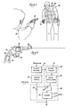
- FIGURE 1 illustrates a typical use of the present invention.
- FIGURE 1 shows two men engaged in a simulated gunfight. Each man operates a laser simulation weapon 12 and wears a receiver garment 14. As shown, the weapons 12 are in the form of handguns, specifically modified revolvers that weigh and handle in the same fashion as a standard law enforcement short range handgun.
- the receiver garments 14 are preferably in the form of vests fitting loosely over the upper body of the respective participants without hindering the participants' movements in any respect.
- each weapon 12 includes the parts necessary to permit operation of the weapon to emit a laser beam of characteristic qualities.
- the gun illustrated is a standard law enforcement revolver that has been modified to render it incapable of shooting live ammunition.
- the barrel has been plugged and the chamber modified to accept special blank cartridges for simulating the sound of live ammunition.
- the electronic circuitry for the weapon 12 is illustrated in FIGURE 3, with the physical disposition of the elements being illustrated in FIGURE 2.
- the major physical pieces of the laser system are a power supply 16, electronic circuitry 18, a trigger sensor 19, and a laser transmitter 20.
- the weapon 12 includes a trigger 22 for actuating the laser system.
- the trigger sensor 19 operates in response to the pulling of the trigger 22 to provide a trigger signal to a gating circuit 26 in the electronic circuitory 18.
- the gating circuit 26 supplies an enabling signal to a gated oscillator 28 in the electronic circuitory 18.
- the gated oscillator 28 then provides signals to a silicon controlled rectifier (SCR) 30 in the laser transmitter 20.
- SCR silicon controlled rectifier
- a capacitor 32 in the laser transmitter 20 is charged from the power supply 16 and discharged upon triggering of the SCR 30 to apply power to a laser 31 within the laser transmitter 20 in pulses in synchronism with the signals from the gated oscillator 28.
- the frequency of the gated oscillator 28 may be 500 Hz, thus producing a pulse every 2 milliseconds.
- the gating circuit 26 may enable the gated oscillator 28 for a predetermined number of cycles, or for a particular period.
- the gating circuit 26 may be a one shot multivibrator enabling the gated oscillator 28 to produce eight pulses 2 milliseconds apart.
- the laser transmitter 20 will thereupon produce a burst of coherent light in a series of eight pulses 2 milliseconds apart each time the trigger 22 is pulled.
- the light may be infrared.
- Each participant therefore, aims and fires his weapon 12 in a conventional manner, attempting to shoot his opponent in the upper body, trying either to "wound" him or to "kill” him, as the case may be. Meanwhile, of course, his opponent may be firing back.
- the receiver garment 14 worn by each participant provides a means for scoring or indicating how well his fellow participant is performing.
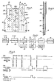
- the exterior of the receiver garment 14 is illustrated in FIGURE 4, and a partial cross section is illustrated in FIGURE 5.
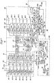
- a block diagram of the electronic circuitry of the weapons garment 14 is illustrated in FIGURE 6, with a more detailed circuit diagram being shown in FIGURE 7.
- the receiver garment 14 is formed of a fabric cover 34, which covers the upper body of each participant, both front and back.
- the cover 34 is divided on each of the front and the back into seven zones 36-1 to 36-7 and 36-8 to 36-14, respectively.
- Photosensitive detectors 38 are distributed relatively uniformly over the entire outside of the front and back of the cover 34 so as to provide relatively uniform detection of laser beams striking the upper body of the participant, wherever the beams might strike.
- a plurality of photosensitive detectors 38 are disposed in each zone 36. There are sufficient detectors placed sufficiently close together that a laser beam will strike one or other of the detectors 38, no matter where the beam strikes the garment 14.
- the photosensitive detectors 38 may comprise photodiodes at the surface of the receiver garment 14.
- the photosensitive detectors may comprise a fiber optics network which pipe the received laser emissions to respective photodiodes located within the body of the receiver garment 14.
- the distal ends of the fiber optics light conductors may be considered the light receptors of respective photosensitive detectors 38, and distribution of the photosensitive detectors 38 may be effected by appropriate distribution of the distal ends of such fiber optics light conductors.
- reference herein to photosensitive detectors distributed over each of a plurability of descrete zones on the outside of the garment includes the alternative wherein fiber optics couples receptors distributed over respective zones to respective photodiodes within the garment.
- the front and back of the garment 14 are essentially the same, with the two halves joined by shoulder pieces 40 and held together by straps 42.
- a visual indicator 44 which may be in the form of light emitting diodes (LED's) 44-1 to 44-7, there being corresponding indicators on the back.
- LED's light emitting diodes
- the visual indicator 44 in the respective zone 36 lights up, indicating a hit.
- a lamp 48 or a lamp 46 mounted on a shoulder piece 40 lights up, indicating whether the hit represents a lethal or incapacitating hit, or represents merely a lesser wound hit.
- a buzzer 50 is affixed to a shoulder piece 40 for providing an audible indication of a hit.
- the weapons garment 14 is self-contained in that it contains all of the electronics and power supplies as required to detect the incoming laser light signals, decode them, and provide appropriate output for driving the respective visual indicators 44, lamps 46 and 48 and buzzer 50.
- the electronics may be encapsulated in a module 52 attached internally of the receiver garment 14 by suitable attaching means.
- the garment 14 may include an inner lining 56 fastened to the cover 34 by sewing or other means, such as straps 58.
- the photosensitive detectors 38-1 to 38-7 in respective zones 36-1 to 36-7 respond to light striking them to produce signals which are amplified and applied to comparators 64 in the form of electrical detection pulses systematically related to the incident light. There the respective pulses, are compared with a reference level V-REF. Those signals exceeding the reference level produce discriminated detection pulses that are applied to hit detectors 66.
- the comparators 64 thus act to discriminate against background light.
- the discriminated detection signals that have passed the discrimination level of the comparators 64 are applied to a decoder 68 which responds to discriminated detection signals having an appropriate temporal pattern corresponding to that of the signals from the laser transmitter 20.
- the decoder 68 identifies such signals occurring at a particular time interval or at a particular frequency and applies an enabling signal to the hit detectors 66 to enable the hit detectors to accept respective discriminated signals from the comparator circuits 64 when such signals are validated by the decoder 68. This further discriminates in favor of signals arising from operation of the laser transmitter 20.
- the output signals from the hit detectors 66 are hit signals identifying hits in particular respective zones 36. These hit signals are applied to a priority circuit 70 which selects among the hit signals in accordance with a hierarchy or priority. That is, the respective zones 36 are assigned particular priority in accordance with a predetermined plan. More especially, the zones 36 are arranged generally in order of degree of damage likely to be produced by a bullet striking tl person wearing the vest 14 in particular respective zones 36. Highest priority is awarded to the zone 36-1 lying at the wearer's breastbone over his heart. The next highest priority is awarded zone 36-2 just above, near the throat and upper chest. The next lesser priorities go to zones 36-3 and 36-4 flanking the firs and second zones. The next is the zone 36-5 in the lower center of the vest 14.
- FIGURE 4 illustrates the respective zones 36 for the front of the receiver garment 14. Corresponding zones are on the back of the receiver garment 14.
- the priority circuit 70 thus selects the hit signal corresponding to a hit in the zone 36 of highest priority and applies it to latch circuits 72, setting latch corresponding to the respective zone.
- a latch signal from the latch circuits 72 is applied to a respective indicator 44-1 to 44-7, causin the respective indicator 44 to light up.
- signals from the priority circuit 70 are applied.
- a lamp circuit 74 to cause a respective lamp 46 or 48 light up, depending upon the priority. More particularly, the hit detection signals corresponding respective zones 36-1 to 36-5 cause the lamp 48, whicl may be red, to light up, indicating a kill or incapacitating wound, whereas a hit in the other zone: 36-6 and 36-7 causes the lamp 46, which may be yellow, to light up. Whichever lamp is lit, a signal is appl: to a buzzer circuit 76 to operate the buzzer 50.
- the photodetectors 38-1 to 38-7 may include respective photodiodes 77-1 to 77-7, there being a plurality of photodetectors 38 in each zone 36.
- the photodiodes 7 for each zone 36 are connected in parallel between a voltage source V+ and a respective resistor 78-l to 78-7.
- Light striking a photodiode 77 causes the flow of current through a respective resistor 78, generating an electrical pulse.
- These electrical pulses are amplified by respective amplifiers 79 of the photosensitive detectors 38 to produce amplified electrical detection pulses systematically related to the light striking the respective photodiodes.
- These amplified pulses which may be considered the detection pulses of the respective photosensitive detectors 38, are applied to respective comparators 64.
- Each comparator 64 compares the amplified electrical detection pulses arising from light striking a particular respective zone 36 with the voltage reference level V-REF and produces a low output discriminated detection pulse whenever an amplified electrical detection pulse exceeds the voltage reference level.
- the discriminated detection pulses are developed at respective output terminals Pl to P7 of the comparator 64 and are applied to the input terminals Pl to P7 of the decoder 68.
- Similar photodetectors 38 and comparators circuits 64 for the zones 36 on the back of the receiver garment 14 produce comparable discriminated detection pulses on terminals P8 through P14. As noted above, the respective terminals Pl to P14 go low whenever an amplified electrical detection pulse exceeds the voltage reference level. Otherwise the respective signal levels remain high.
- the signals at the terminals P8 through P14 are applied to a NAND gate 80 which thus produces a high output whenever the discrimination level is exceeded by the light striking the photodiodes of a respective zone 36 on the back of the receiver garment 14.
- This signal is inverted by an inverter 82 and applied to a NAND gate 84 along with the signals from the output terminals Pl to P7.
- the output of the NAND gate 84 goes high for the duration of such pulse.
- the signals at the output of the NAND gate 84 thus comprise the sum of the discrimination detection pulses and appear in the form illustrated by waveform 8A in FIGURE 8.
- the output of the NAND gate 84 goes high.
- This high signal is applied to one input of a two input AND gate 88, the other input being normally high.
- the high signal applied to the AND gate 88 causes the output thereof to go high.
- This signal is inverted by an inverter 90 and applied to one input of an AND gate 92. With the signal at this input low, the output of the AND gate 92 goes low irrespective of the other input to the AND gate 92.
- This signal from the AND gate 92 is inverted by an inverter 94 and applied to the R terminal of a 7 stage binary counter 96 (type 4024) which counts pulses applied from a clock 98.
- the clock 98 operates at a frequency of 40 KHz for the purpose of decoding a 500 Hz pulsed laser beam.
- the output of the NAND gate 84 is also applied to a NOR R-S latch 100 (type 4043).
- the Q output of the NOR R-S latch 100 is also applied to the AND gate 92.
- the quiescent state of the decoder 68 that is, the period between cycles, the input to the AND gate 88 from the NAND gate 84 is low, the other input to the AND gate 88 is high, the inputs to the R and S terminals of the NOR R-S latch 100 are low, and the Q output of the NOR R-S latch 100 is low.
- the latter holds the output of the AND gate 92 low, operating through the inverter 94 to apply a high signal to the R terminal of the counter 96, thus holding the counter 96 in its reset condition.
- the high signal to the S terminal of the NOR R-S latch 100 causes the Q output to go high.
- the high signal to the AND gate 88 causes its output to go high for the duration of the pulse, but the output thereafter goes low.
- This low signal is inverted by the inverter 90.
- both inputs to the AND gate 92 are then high, its output goes high.
- any high pulse applied to the AND gate 88 from the NAND gate 84 will cause the 7 stage binary counter 96 to be reset, with the counting beginning again at the end of the pulse.
- the output terminal Q6 of the 7 stage binary counter 96 will go high after 0.8 milliseconds and remain high for another 0.8 milliseconds, whereupon it will go low, and the output terminal Q7 will go high at 1.6 milliseconds.
- the terminal Q6 will again go high after another 0.8 milliseconds, the terminal Q7 remaining high.
- the outputs from terminals Q6 and Q7 are applied to an AND gate 102, the output of which thus goes high at 2.4 milliseconds after the starting of counting of the clock pulses by the seven stage binary counter 96.
- the output of the AND gate 102 is applied to the R terminal of the NOR R-S latch 100. Unless a subsequent pulse happens to be at the same time applied from the NAND gate 84, the S terminal of the NOR R-S latch 100 will be low. Even if the S terminal is coincidently high, it will go low at the end of the pulse. Consequently, the appearance of a high signal on the R terminal causes the Q terminal to go low. This operates through the AND gate 92 and the inverter 94 to reset, but not restart, the 7 stage binary counter 96.
- the output from the terminal Q7 of the NOR R-S latch 100 is applied through an inverter 104 to the AND gate 88 to disable the AND gate 88 for the interval between 1.6 milliseconds and 2.4 milliseconds. This prevents a signal from the NAND gate 84 from operating through the AND gate 88 to reset the NOR R-S latch 100 during this interval.
- the Q6 and Q7 output terminals from the seven stage binary counter 96 go low, thus driving the R terminal of the NOR R-S latch 100 low and operating through the inverter 104 to enable the AND gate 88.
- This places the NOR R-S latch 100 in the quiescent condition for restarting the 7 stage binary counter 96 as described above and enabling the AND gate 88 to permit a pulse from the NAND gate 84 to operate through the AND gate 88 to reset the 7 stage binary counter 96, as also described above.
- the decoder 68 is thus in condition for decoding the next received burst of discriminated detection pulses occasioned by a subsequent firing of the laser transmitter 20.
- the signal at the terminal Q7 of the seven stage binary counter 96 operates as an enabling signal for the hit detectors 66, which comprise NAND R-S latches 106-1 to 106-7 (type 4044). That is, the signal at the terminal Q7 provides a window in time during which signals applied to the S terminals of the respective NAND R-S latches 106-1 to 106-7 may operate to provide respective hit signal outputs at.their respective Q terminals. This valid signal window is shown by waveform 8B. Except during the window, the respective R terminals of the NAND R-S latches 106 are low.
- the inputs to the respective S terminals are high except upon the detection of light by the respective photodiodes 38-1 to 38-7 of sufficient intensity that the respective amplified electrical detection pulses exceed the reference level of the comparators 64, producing corresponding discriminated detection pulses. Even then the Q outputs will all remain low, irrespective of the S inputs, so long as the R terminals are low. This means that when the respective S terminals go low, there is no change in the respective Q terminals so long as the R terminals have not been enabled by the signal from the Q7 terminal of the 7 stage binary counter 96. When the R terminals go high upon the occurrence of such enabling window, the respective output terminals remain low while the S terminals are high.
- This decoding of the signals may be further understood by reference to the waveforms of FIGURE 8.
- the signals exceeding the discrimination level V-REF of the comparators 64 produce discriminated detection signals that are applied to the NAND gate 84 to produce signals in the form shown in waveform 8A.
- the first pulse operates through the NOR R-S latch 100 to start the 7 stage binary counter 96.
- Subsequent pulses reset and restart the 7 stage binary counter 96 by way of the AND gate 88, so long as such as pulses occur prior to the beginning of a window signal (waveform 8B) at the terminal Q7 of the 7 stage binary counter 96, as such window signal operates to disable the AND gate 88 and hence prevent resetting and restarting.
- a valid signal window signal is developed at the terminal Q7 of the 7 stage binary counter 96 in the form shown by waveform 8B.
- a hit signal appears at a respective terminal Q of a NAND R-S latch 106, as shown by waveform 8C. Pulses appearing at the output of the NAND gate 84 prior to a valid signal window operate to reset the timing of the 7 stage binary counter 96, and a pulse appearing after the end of a valid signal window operates to restart the counter 96, but none of these operate a NAND R-S latch 106.
- the hit signal outputs of the hit detectors 66 are applied in parallel to an 8 bit priority encoder 108 (type 4532) of the priority circuit 70.
- the 8 bit priority encoder 108 operates in response to applied high signals to indicate in octal code on outputs Q0, Ql and Q2 a high signal on the input line that has the highest priority. In this instance the priorities are assigned in numerical order for zones 36-1 to 36-7.
- These signals from terminals Q0, Ql and Q2 are applied to the input terminals of an 8 channel multiplexer 110 (type 4051) which applies signals to the S terminals of corresponding NOR R-S latches 112-1 to 112-7 (type 4043) of the latch circuits 72 when the 8 channel multiplexer 110 is not inhibited.
- the 8 channel multiplexer 110 is inhibited by a signal applied to its terminal INH.
- a signal is applied from the GS terminal of the 8 bit priority encoder 108 upon receipt of an input high signal to any of its input terminals.
- This signal from the GS terminal is a strobe signal applied to an 800 nanosecond one shot multivibrator 114, which thereupon produces a high output signal at its terminal Q.
- This signal is applied through a 100 nanosecond delay circuit to a two input AND gate 118, the other input to the AND gate 118 being normally high.
- the high signal thus applied to the AND gate 118 causes the output of the gate 118 to go high.
- This high is inverted to a low by an inverter 120 and applied to the INH terminal of the 8 channel multiplexer 110 to enable the multiplexer to transfer the signal identifying the hit zone to a respective NOR R-S latch 112.
- the 100 nanosecond delay in enabling the 8 channel multiplexer 110 is to assure that transients have cleared the lines connected to the terminals Q0, Ql and Q2 of the 8 bit priority encoder 108 before the signals are read out and transmitted by the 8 channel multiplexer 110.
- the output from the 800 nanosecond one shot multivibrator 114 is also applied to a 45 millisecond one shot multivibrator 122. This multivibrator is triggered by the turning off of the 800 nanosecond one shot multivibrator 114. Its normally high output is driven low for 45 milliseconds. This operates to drive the output of the AND gate 118 low and hence inhibits the 8 channel multiplexer 110 after the 800 nanosecond one shot for a period of 45 milloseconds thereafter.
- the purpose of this is to assure that no hit signals are transmitted to the NOR R-S latches l12 after the first decoded hit pulse of a group. This is because the pulses are transmitted in bursts of eight, and subsequent pulses may be passed by the decoder 68 for subsequent pairs of pulses in the same burst. It is not desired that such be effective to indicate hits; hence, the 45 microsecond one shot multivibrator 122 precludes the transmission of such information for the remainder of the length of time it takes for the burst of pulses.
- the NOR R-S latches 112-1 to 112-7 are placed in their reset condition by the momentary closing of a switch 124, which applies a high signal to the respective R terminals.
- the S terminals are normally low, being driven high only when a hit is decoded by the operation of the hit detectors 66, the decoder 68 and the priority circuit 70.
- the NOR R-S latches 112 thus normally provide a low output at their respective Q terminals.
- the respective NOR R-S latch 112 changes state and provides a high at its Q output terminal.
- This high operates through a respective resistor 126 to turn on a respective transistor 128 which in turn operates through a respective resistor 130 to turn on a respective visual indicator 44-1 to 44-27.
- These visual indicators 44-1 to 44-7 may be appropriate LED's connected to a power supply, not shown, so that when a respective transistor 128 is made conductive, the corresponding LED 44 emits light to indicate a hit in the zone 36 of highest priority amongst the zones 36 detecting the pulses from the laser transmitter 20.
- the respective visual indicators 44 remain lit until the switch 124 is again momentarily closed to reset the NOR R-S latches 112.
- the switch 124 may be a push-button switch. The visual indicators 44 thus remain lit until appropriate note is made of the respective hits, permitting scoring and evaluation.
- OR gate 132 receives its inputs from terminals Ql and Q2 of the 8 bit priority encoder 108.
- the output of the OR gate 132 thus goes high whenever there is a hit on any of zones 36-1 to 36-5, which hits are sufficient to exceed the discrimination level of the comparators 64 and are registered on the respective NAND R-S latches 106-1 to 106-5.
- OR gate 134 receives its inputs from the outputs of the 8 channel multiplexer 110 corresponding to zones 36-6 and 36-7. Hence, its output goes high whenever there is a hit in either of zones 36-6 and 36-7.
- the output of the OR gate 132 together with the output of a similar OR gate from circuitry related to the back of the receiver garment 14 is applied to the lamp circuit 74. More specifically, the two inputs from the OR gate 132 and its counterpart are applied to an OR gate 136 which provides a high output when there are hits in any of the higher priority zones 36-1 to 36-5 and the corresponding zones on the back. This high signal energizes a one second one shot multivibrator 138 to provide a low output for one second at its output terminal. This low is inverted by an inverter 140 and applied through a resistor 142 to turn on a transistor 144, thereby turning on the red lamp 48, indicating a hit in a high priority zone 36.
- the outputs from the OR gate 134 and its counterpart on the back are applied to an OR gate 146 which operates a one second one shot multivibrator 148.
- the output of the one shot multivibrator 148 is inverted by an inverter 150 and applied through a resistor 152 to operate a transistor 154, thereby turning on the yellow lamp 46, indicating a hit in a low priority zone 36-6 or 36-7 or one of their counterparts on the back.
- the outputs of the one second one shot multivibrators 1.38 and 148 are also applied through respective inverters 156 and 158, thence through respective resistors 160 and 162 to turn on respective transistors 164 and 166. These, in turn, turn on the buzzer 50 for the periods of the respective one second one shot multivibrators 138 and 148.
- the buzzer 50 may be disabled by opening a buzzer switch 168.
- a capacitor 170 is charged through a resistor 172 when power is first turned on. This develops a low signal which changes to a high signal as the capacitor 170 charges and is applied through an inverter 174 and thence through a resistor 176 to operate a transistor 178.
- the transistor 178 operates the buzzer 50 - momentarily upon turn-on of power, thus indicating that the power is turned on and that the buzzer is operating.
- the decoder 68, the lamp circuit 74 and the buzzer circuit 76 are common to the circuitry for both the front and the back of the receiver garment 14.
- the remainder of the elements illustrated in FIGURE 7, as shown for the front of the receiver garment 14, are duplicated for the back.
- the visual indicators 44-1 to 44-7 remain lit until turned off manually by the operation of the switch 124.
- the respective lamps 46 and 48 and the buzzer 50 remain operating only for the period of the respective one shot multivibrators 138 and 148.
- participants in a simulated gun fight each have a simulated weapon 12 including a laser transmitter 20 for transmitting pulses of directed coherent light in a characteristic temporal pattern.
- Each wears a receiver garment 14 having a cover 34 covering at least a substantial portion of his front upper body.
- the cover has a plurality of discreet zones 36 on the outside thereof.
- there are at least two participants in order that the simulated gunfight may be more realistic, particularly in matters of stress and defense.
- the participants shoot their respective simulated weapons by pulling the triggers 22 of their weapons 12, thereby causing the respective laser transmitters 20 to emit the pulses of directed coherent light in bursts in a characteristic temporal pattern.
- the decoder 68 responds to the discriminated detection pulses and compares their temporal pattern with a pattern characteristic of the laser transmitter. More particularly, when the laser transmitter 20 is operating at a frequency of 500 cycles, the decoder 68 senses when successive pulses are spaced by approximately two milliseconds, specifically, in the present example, by a time between 1.6 milliseconds and 2.4 milliseconds.
- the decoder 68 produces a valid signal window signal which enables the respective hit detectors 66 to produce a hit signal when a succeeding pulse comes within the window.
- the priority circuit 70 determines the zone 36 of highest priority in which a hit has been detected and applies a signal to an appropriate one of the latches 72, which in turn activates a corresponding visual indicator 44.
- the appropriate indicator 44 is thus a visual indicating means which is disposed in the respective zone 36 for providing a visual signal when actuated that identifies the zone 36 in which a hit has been made. Such actuation is, of course, occasioned by the actuating means comprising the priority circuit 70 and the latches 72.
- the lamp circuit 74 responds to particular outputs from the priority circuit 70, whereby one of the lamps is lit upon the occurrence of a hit signal corresponding to a zone 36 having at least a predetermined level of priority, for example, in the present invention, the priority of zones 36-1 to 36-5. The other lamp is lit when there is a hit in a zone 36 of lesser priority.
- the buzzer 50 sounds to provide an audible signal upon the occurrence of any hit signal.
- the buzzer 50 and the lamps 46 and 48 are automatically turned off after a short interval, the period of the respective one shot multivibrators 138, 148.
- the visual indicating means 44 are turned off manually at such later time as desired, thus permitting analysis of the hits.
- the simulated weapon may be other than a handgun, and the temporal pattern may be other than a particular frequency.
- the laser beam may be pulse-code-modulated.
- the receiver garment may be other than a vest. It may, for example, be in the nature of a bib, or it may be a more complete garment, such as a jacket with sleeves, or indeed coveralls with photodetectors over the entire garment.
- the photodetectors may be other than photodiodes. Other discrimination means may be used and other decoding circuits. Other visual indicating means may be used.
- the buzzer may be differently energized so as to produce different sounds, depending upon the priority of the hit. It is possible to arrange the priorities in a different manner.
Landscapes
- Engineering & Computer Science (AREA)
- General Engineering & Computer Science (AREA)
- Radar, Positioning & Navigation (AREA)
- Optical Radar Systems And Details Thereof (AREA)
- Aiming, Guidance, Guns With A Light Source, Armor, Camouflage, And Targets (AREA)
Applications Claiming Priority (2)
| Application Number | Priority Date | Filing Date | Title |
|---|---|---|---|
| US273774 | 1981-06-15 | ||
| US06/273,774 US4487583A (en) | 1981-06-15 | 1981-06-15 | Receiver garment for weapons engagement simulation system |
Publications (2)
| Publication Number | Publication Date |
|---|---|
| EP0067654A2 true EP0067654A2 (de) | 1982-12-22 |
| EP0067654A3 EP0067654A3 (de) | 1985-05-08 |
Family
ID=23045339
Family Applications (1)
| Application Number | Title | Priority Date | Filing Date |
|---|---|---|---|
| EP82302956A Withdrawn EP0067654A3 (de) | 1981-06-15 | 1982-06-08 | Empfangskleidung zum Simulieren eines Waffenkampfes |
Country Status (6)
| Country | Link |
|---|---|
| US (1) | US4487583A (de) |
| EP (1) | EP0067654A3 (de) |
| AU (1) | AU547179B2 (de) |
| CA (1) | CA1191258A (de) |
| ES (1) | ES8306871A1 (de) |
| ZA (1) | ZA823828B (de) |
Cited By (15)
| Publication number | Priority date | Publication date | Assignee | Title |
|---|---|---|---|---|
| FR2545204A1 (fr) * | 1983-04-26 | 1984-11-02 | Aubourg Philippe | Vetement autonome associe a un systeme laser de designation de personne |
| GB2153498A (en) * | 1984-01-31 | 1985-08-21 | Photon Marketing | Amusement shooting game |
| GB2169995A (en) * | 1985-01-11 | 1986-07-23 | John Francis Shortall | Portable electronic toy |
| FR2578042A1 (fr) * | 1985-02-27 | 1986-08-29 | Precitronic | Dispositif d'exercice de pointage avec une arme a feu |
| US4695058A (en) * | 1984-01-31 | 1987-09-22 | Photon Marketing Limited | Simulated shooting game with continuous transmission of target identification signals |
| DE3631081A1 (de) * | 1986-09-12 | 1988-03-24 | Helge Eichholz | Schiesssimulator fuer gebrauchs- und sportschuetzen, zielscheibenanordnung fuer einen schiesssimulator und verfahren zur anzeige des auftreffpunktes eines von einer waffenattrappe des schiesssimulators ausgesandten lichtstrahls |
| EP0232157A3 (de) * | 1986-02-07 | 1989-01-25 | Worlds Of Wonder, Inc. | Spiel mit Zielschiessen |
| WO1995030125A1 (en) * | 1994-04-29 | 1995-11-09 | Cubic Defense Systems, Inc. | Multiple integrated laser engagement system employing fiber optic detection signal transmission |
| FR2728335A1 (fr) * | 1994-12-16 | 1996-06-21 | Advanced Laser Ind Systems | Cible photosensible et application a la realisation d'un gilet pour l'entrainement par simulation de tir |
| EP0619130A3 (de) * | 1993-03-02 | 1996-08-21 | Golden Grid Ltd | Elektronisches Schiessspiel. |
| EP0854348A1 (de) * | 1997-01-13 | 1998-07-22 | SE Schweizerische Elektronikunternehmung | Akustisches Unterstützungssystem |
| WO2004102106A1 (en) * | 2003-05-15 | 2004-11-25 | Stefano Valentini | System for detecting and recording impacts produced by shock waves and projectiles on a target |
| US8517844B2 (en) * | 2008-11-26 | 2013-08-27 | Sgf Sueddeutsche Gelenkscheibenfabrik Gmbh & Co. Kg | Torque transmitting device |
| IT201600108710A1 (it) * | 2016-10-27 | 2018-04-27 | Lacs S R L | Un assieme di rilevamento di fasci elettromagnetici |
| WO2023143715A1 (de) | 2022-01-26 | 2023-08-03 | Wraneschitz Alfred | Flächensensor zum erfassen eines einfallenden lichtsignals |
Families Citing this family (60)
| Publication number | Priority date | Publication date | Assignee | Title |
|---|---|---|---|---|
| US4586715A (en) * | 1982-12-30 | 1986-05-06 | Life Light Systems | Toy laser pistol |
| US4754133A (en) * | 1986-04-25 | 1988-06-28 | Williams Electronics Games, Inc. | Transceiver circuit for modulated infrared signals |
| US4743030A (en) * | 1986-09-03 | 1988-05-10 | Buddy L Corporation | Water gun and target combat game set |
| US4823401A (en) * | 1987-12-04 | 1989-04-18 | Applied Solar Energy Corporation | "MILES" transceiver display controller unit |
| US4898391A (en) * | 1988-11-14 | 1990-02-06 | Lazer-Tron Company | Target shooting game |
| US4934937A (en) * | 1988-12-14 | 1990-06-19 | Tommy Judd | Combat training system and apparatus |
| US5194007A (en) * | 1991-05-20 | 1993-03-16 | The United States Of America As Represented By The Secretary Of The Navy | Semiconductor laser weapon trainer and target designator for live fire |
| US5222741A (en) * | 1992-01-08 | 1993-06-29 | Mark Redl Inc. | Tactical target system |
| US5354057A (en) * | 1992-09-28 | 1994-10-11 | Pruitt Ralph T | Simulated combat entertainment system |
| US5320358A (en) * | 1993-04-27 | 1994-06-14 | Rpb, Inc. | Shooting game having programmable targets and course for use therewith |
| EP0773699A1 (de) * | 1994-05-31 | 1997-05-14 | Capcom Co., Ltd. | Schallabtasteinrichtung, spielgerät, verfahren zu dessen steuerung, spielgerät mit lichtstrahl und akustisches gerät |
| GB9413203D0 (en) * | 1994-06-30 | 1994-08-24 | Rapidville Limited | Amusement apparatus |
| US5676548A (en) * | 1995-11-21 | 1997-10-14 | Mcalpin; Jim L. | Apparatus for target practice |
| US5788500A (en) * | 1995-12-04 | 1998-08-04 | Oerlikon-Contraves Ag | Continuous wave laser battlefield simulation system |
| US5785592A (en) * | 1996-08-12 | 1998-07-28 | Sarcos, Inc. | Interactive target game system |
| US6780014B1 (en) | 1996-11-26 | 2004-08-24 | Lightshot Systems, Inc. | Pattern testing board and system |
| US5984788A (en) * | 1997-06-09 | 1999-11-16 | Toymax Inc. | Interactive toy shooting game having a target with a feelable output |
| DE19729475C1 (de) * | 1997-07-10 | 1998-04-30 | C O E L Entwicklungsgesellscha | Schußsimulationsverfahren und Vorrichtung zur Durchführung des Verfahrens |
| US6261180B1 (en) * | 1998-02-06 | 2001-07-17 | Toymax Inc. | Computer programmable interactive toy for a shooting game |
| US6863532B1 (en) * | 1999-03-10 | 2005-03-08 | Franco Ambrosoli | Equipment for detecting that a target has received a direct hit from a simulated weapon |
| JP3249492B2 (ja) * | 1999-06-30 | 2002-01-21 | 株式会社スクウェア | コンピュータ読み取り可能な記録媒体、ゲームの制御方法およびゲーム装置 |
| US6293869B1 (en) | 1999-12-30 | 2001-09-25 | Toymax Inc. | Shooting game target with graphic image display device |
| US6482064B1 (en) * | 2000-08-02 | 2002-11-19 | Interlego Ag | Electronic toy system and an electronic ball |
| US6526688B1 (en) * | 2001-08-13 | 2003-03-04 | Lewis Danielson | Apparatus and method for actuating a weapon accessory by a laser sighting beam |
| US20030125110A1 (en) * | 2001-12-27 | 2003-07-03 | Lalley Timothy J. | Games utilizing electronic display strips and methods of making display strips |
| GB0202472D0 (en) * | 2002-02-02 | 2002-03-20 | Qinetiq Ltd | Device and methods for the calibration and control of thermal detectors |
| JP3888450B2 (ja) * | 2002-05-10 | 2007-03-07 | 日本電気株式会社 | 標的装置及び光検出装置 |
| AU2003291056A1 (en) * | 2002-11-18 | 2004-06-15 | Soft Play, L.L.C. | Interactive laser amusement systems |
| US20050206616A1 (en) * | 2004-03-17 | 2005-09-22 | Franz Harary | Video jacket, belt and badge and method of use |
| WO2006096192A1 (en) * | 2004-06-09 | 2006-09-14 | Honeywell International, Inc. | Communications system based on real-time neurophysiological characterization |
| US20060028430A1 (en) * | 2004-06-21 | 2006-02-09 | Franz Harary | Video device integratable with jacket, pants, belt, badge and other clothing and accessories and methods of use thereof |
| CH697725B1 (it) | 2004-11-05 | 2009-01-30 | Stefano Valentini | Impianto per il rilevamento di impatti. |
| US7284280B2 (en) * | 2005-04-05 | 2007-10-23 | Gregory Russell Schultz | Energy weapon protection device |
| US7499713B2 (en) * | 2005-04-28 | 2009-03-03 | Northrop Grumann Corporation | Systems and methods for condition and location monitoring of mobile entities |
| US20060287114A1 (en) * | 2005-06-03 | 2006-12-21 | Binh Luong | Electronic tag game |
| EP1737146B1 (de) * | 2005-06-22 | 2015-09-16 | Saab Ab | Vorrichtung und Verfahren zur Datenübertragung |
| US7980719B2 (en) * | 2006-03-08 | 2011-07-19 | Production Resource Group, L.L.C. | Digital light with target effects |
| US8128450B2 (en) | 2006-05-04 | 2012-03-06 | Mattel, Inc. | Thermochromic transformable toy |
| JP5042547B2 (ja) * | 2006-07-12 | 2012-10-03 | 株式会社日立国際電気 | 射撃シミュレーション装置の被弾現示装置 |
| DE102006039787A1 (de) * | 2006-08-24 | 2008-03-20 | Siemens Ag | Verfahren zur Detektion eines Objektes als passives Ziel einer Markierung mittels eines Lichtstrahls |
| US8157565B2 (en) * | 2007-02-01 | 2012-04-17 | Raytheon Company | Military training device |
| US8001999B2 (en) | 2008-09-05 | 2011-08-23 | Olive Tree Financial Group, L.L.C. | Energy weapon protection fabric |
| US20110126335A1 (en) * | 2009-12-01 | 2011-06-02 | Gregory Russell Schultz | Staple Fiber Conductive Fabric |
| KR101914314B1 (ko) * | 2010-12-09 | 2018-11-01 | 제임스 퀘일 제프리 | 전기 충격 스트레스 노출 훈련을 위한 컨트롤러 |
| US9429404B2 (en) | 2011-01-18 | 2016-08-30 | Larry E. Moore | Laser trainer target |
| WO2013002876A2 (en) * | 2011-05-23 | 2013-01-03 | Kangas Miikka M | Handheld laser small arm |
| US9163894B1 (en) | 2011-10-28 | 2015-10-20 | Lockheed Martin Corporation | Laser transmission system for use with a firearm in a battle field training exercise |
| CN102430241B (zh) * | 2011-12-05 | 2014-12-03 | 马卡里 | 一种真人cs用背心 |
| US9146078B2 (en) * | 2012-01-17 | 2015-09-29 | Jeffrey James Quail | Adapter for communicating between an anti-personnel training device and a user worn monitoring device |
| US10532275B2 (en) | 2012-01-18 | 2020-01-14 | Crimson Trace Corporation | Laser activated moving target |
| CN203208654U (zh) * | 2013-02-07 | 2013-09-25 | 马卡里 | 一种真人cs游戏道具 |
| US9182194B2 (en) | 2014-02-17 | 2015-11-10 | Larry E. Moore | Front-grip lighting device |
| US9644826B2 (en) | 2014-04-25 | 2017-05-09 | Larry E. Moore | Weapon with redirected lighting beam |
| US10436553B2 (en) | 2014-08-13 | 2019-10-08 | Crimson Trace Corporation | Master module light source and trainer |
| US10132595B2 (en) | 2015-03-20 | 2018-11-20 | Larry E. Moore | Cross-bow alignment sighter |
| US9829280B1 (en) * | 2016-05-26 | 2017-11-28 | Larry E. Moore | Laser activated moving target |
| US10209030B2 (en) | 2016-08-31 | 2019-02-19 | Larry E. Moore | Gun grip |
| US10436538B2 (en) | 2017-05-19 | 2019-10-08 | Crimson Trace Corporation | Automatic pistol slide with laser |
| US10209033B1 (en) | 2018-01-30 | 2019-02-19 | Larry E. Moore | Light sighting and training device |
| US12250099B2 (en) * | 2021-09-08 | 2025-03-11 | PassiveLogic, Inc. | External activation of quiescent device |
Family Cites Families (16)
| Publication number | Priority date | Publication date | Assignee | Title |
|---|---|---|---|---|
| US3549147A (en) * | 1968-06-06 | 1970-12-22 | Gene S Katter | Gunnery training apparatus |
| US3633285A (en) * | 1970-03-09 | 1972-01-11 | Litton Systems Inc | Laser markmanship trainer |
| GB1383564A (en) * | 1972-07-29 | 1974-02-12 | Solartron Electronic Group | Umpires ray gun for use in weapon training systems |
| US3792535A (en) * | 1972-12-11 | 1974-02-19 | Us Navy | Laser rifle simulator system |
| US3811204A (en) * | 1973-03-22 | 1974-05-21 | Us Navy | Programmable laser marksmanship trainer |
| US3898747A (en) * | 1974-06-24 | 1975-08-12 | Us Navy | Laser system for weapon fire simulation |
| US3938262A (en) * | 1974-10-17 | 1976-02-17 | Hughes Aircraft Company | Laser weapon simulator |
| US3995376A (en) * | 1975-04-03 | 1976-12-07 | Cerberonics, Inc. | Small arms laser training device |
| US4048489A (en) * | 1975-11-10 | 1977-09-13 | Carlo Giannetti | Light operated target shooting systems |
| DE2633042A1 (de) * | 1976-07-26 | 1978-01-26 | Nishi Nippon Denki Co | Zielanordnung fuer impulslichtstrahl mit kreuzweise angeordneten und gruppierten phototransistoren |
| US4063368A (en) * | 1976-08-16 | 1977-12-20 | Manned Systems Sciences, Inc. | Laser weapons simulation system |
| US4150824A (en) * | 1976-08-27 | 1979-04-24 | Walt Disney Productions | Optoelectronic communications system |
| US4195422A (en) * | 1976-12-20 | 1980-04-01 | Laspo Ag | System for simulating weapon firing |
| US4177580A (en) * | 1978-01-23 | 1979-12-11 | The United States Of America As Represented By The Secretary Of The Navy | Laser marksmanship target |
| FR2426479A1 (fr) * | 1978-05-22 | 1979-12-21 | Grandval Gerard | Jeu de tir au pistolet |
| DE2952608A1 (de) * | 1979-12-28 | 1981-07-02 | Heins AG, Glarus | Trainingsanzug |
-
1981
- 1981-06-15 US US06/273,774 patent/US4487583A/en not_active Expired - Fee Related
-
1982
- 1982-06-01 ZA ZA823828A patent/ZA823828B/xx unknown
- 1982-06-07 AU AU84631/82A patent/AU547179B2/en not_active Ceased
- 1982-06-08 EP EP82302956A patent/EP0067654A3/de not_active Withdrawn
- 1982-06-11 CA CA000404940A patent/CA1191258A/en not_active Expired
- 1982-06-14 ES ES513058A patent/ES8306871A1/es not_active Expired
Cited By (16)
| Publication number | Priority date | Publication date | Assignee | Title |
|---|---|---|---|---|
| FR2545204A1 (fr) * | 1983-04-26 | 1984-11-02 | Aubourg Philippe | Vetement autonome associe a un systeme laser de designation de personne |
| GB2153498A (en) * | 1984-01-31 | 1985-08-21 | Photon Marketing | Amusement shooting game |
| US4695058A (en) * | 1984-01-31 | 1987-09-22 | Photon Marketing Limited | Simulated shooting game with continuous transmission of target identification signals |
| GB2169995A (en) * | 1985-01-11 | 1986-07-23 | John Francis Shortall | Portable electronic toy |
| FR2578042A1 (fr) * | 1985-02-27 | 1986-08-29 | Precitronic | Dispositif d'exercice de pointage avec une arme a feu |
| EP0232157A3 (de) * | 1986-02-07 | 1989-01-25 | Worlds Of Wonder, Inc. | Spiel mit Zielschiessen |
| DE3631081A1 (de) * | 1986-09-12 | 1988-03-24 | Helge Eichholz | Schiesssimulator fuer gebrauchs- und sportschuetzen, zielscheibenanordnung fuer einen schiesssimulator und verfahren zur anzeige des auftreffpunktes eines von einer waffenattrappe des schiesssimulators ausgesandten lichtstrahls |
| EP0619130A3 (de) * | 1993-03-02 | 1996-08-21 | Golden Grid Ltd | Elektronisches Schiessspiel. |
| WO1995030125A1 (en) * | 1994-04-29 | 1995-11-09 | Cubic Defense Systems, Inc. | Multiple integrated laser engagement system employing fiber optic detection signal transmission |
| FR2728335A1 (fr) * | 1994-12-16 | 1996-06-21 | Advanced Laser Ind Systems | Cible photosensible et application a la realisation d'un gilet pour l'entrainement par simulation de tir |
| EP0854348A1 (de) * | 1997-01-13 | 1998-07-22 | SE Schweizerische Elektronikunternehmung | Akustisches Unterstützungssystem |
| WO2004102106A1 (en) * | 2003-05-15 | 2004-11-25 | Stefano Valentini | System for detecting and recording impacts produced by shock waves and projectiles on a target |
| US8517844B2 (en) * | 2008-11-26 | 2013-08-27 | Sgf Sueddeutsche Gelenkscheibenfabrik Gmbh & Co. Kg | Torque transmitting device |
| IT201600108710A1 (it) * | 2016-10-27 | 2018-04-27 | Lacs S R L | Un assieme di rilevamento di fasci elettromagnetici |
| EP3315894A1 (de) * | 2016-10-27 | 2018-05-02 | LACS S.r.l. | Anordnung zur detektion von elektromagnetischen strahlen |
| WO2023143715A1 (de) | 2022-01-26 | 2023-08-03 | Wraneschitz Alfred | Flächensensor zum erfassen eines einfallenden lichtsignals |
Also Published As
| Publication number | Publication date |
|---|---|
| ES513058A0 (es) | 1983-06-01 |
| EP0067654A3 (de) | 1985-05-08 |
| AU547179B2 (en) | 1985-10-10 |
| CA1191258A (en) | 1985-07-30 |
| AU8463182A (en) | 1982-12-23 |
| US4487583A (en) | 1984-12-11 |
| ZA823828B (en) | 1983-03-30 |
| ES8306871A1 (es) | 1983-06-01 |
Similar Documents
| Publication | Publication Date | Title |
|---|---|---|
| US4487583A (en) | Receiver garment for weapons engagement simulation system | |
| US3898747A (en) | Laser system for weapon fire simulation | |
| US4352665A (en) | Small arms laser training device | |
| US4662845A (en) | Target system for laser marksmanship training devices | |
| US3995376A (en) | Small arms laser training device | |
| ATE252718T1 (de) | Simulationssystem für schiesssport | |
| WO2001090676A1 (en) | A target shooting scoring and timing system | |
| CN111023893A (zh) | 一种实兵激光模拟对抗训练系统 | |
| US5291680A (en) | Grenade launching apparatus | |
| US4257612A (en) | Optoelectronic amusement device | |
| EP1405029B1 (de) | Verfahren und anordnung zur anzeige von treffern | |
| US6863532B1 (en) | Equipment for detecting that a target has received a direct hit from a simulated weapon | |
| US5199874A (en) | Apparatus and method for interfacing indirect-fire devices with MILES | |
| US20160071426A1 (en) | Target Device for Determining Received Hits in a Light Based Weapons Simulation System | |
| US9057582B2 (en) | Simulation system | |
| KR100222236B1 (ko) | 레이저를 이용한 교전훈련장비 | |
| USH1451H (en) | Audible explosive device simulator system for miles | |
| KR102265348B1 (ko) | 개인용 피해 표시 장치를 이용한 모의교전 훈련 시스템 | |
| KR20120083249A (ko) | 마일즈장비 착용하 모의교전훈련시 중상자 및 사망자 표시장치 | |
| FR2337872A1 (fr) | Simulateur de tir | |
| USH218H (en) | Weapon trainer using IR radiation emitted from target | |
| AU2004203546B2 (en) | Equipment for detecting that a target has received a direct hit from a simulated weapon | |
| WO1994017358A1 (en) | Apparatus and method for interfacing indirect fire devices with miles | |
| CA2223975C (en) | Laser identification system | |
| CA2525043A1 (en) | A transmitting unit |
Legal Events
| Date | Code | Title | Description |
|---|---|---|---|
| PUAI | Public reference made under article 153(3) epc to a published international application that has entered the european phase |
Free format text: ORIGINAL CODE: 0009012 |
|
| AK | Designated contracting states |
Designated state(s): BE CH DE FR GB IT LI NL |
|
| 17P | Request for examination filed |
Effective date: 19830510 |
|
| PUAL | Search report despatched |
Free format text: ORIGINAL CODE: 0009013 |
|
| AK | Designated contracting states |
Designated state(s): BE CH DE FR GB IT LI NL |
|
| 17Q | First examination report despatched |
Effective date: 19870224 |
|
| STAA | Information on the status of an ep patent application or granted ep patent |
Free format text: STATUS: THE APPLICATION IS DEEMED TO BE WITHDRAWN |
|
| 18D | Application deemed to be withdrawn |
Effective date: 19880506 |
|
| RIN1 | Information on inventor provided before grant (corrected) |
Inventor name: BRUCKER, STEPHEN ELLIOT Inventor name: BLANKENSHIP, LARRY KETRON |