EP0067733A2 - Vorrichtung mit doppeltem Sicherheitssystem zum Verteilen von infraroten Düppeln - Google Patents
Vorrichtung mit doppeltem Sicherheitssystem zum Verteilen von infraroten Düppeln Download PDFInfo
- Publication number
- EP0067733A2 EP0067733A2 EP82400860A EP82400860A EP0067733A2 EP 0067733 A2 EP0067733 A2 EP 0067733A2 EP 82400860 A EP82400860 A EP 82400860A EP 82400860 A EP82400860 A EP 82400860A EP 0067733 A2 EP0067733 A2 EP 0067733A2
- Authority
- EP
- European Patent Office
- Prior art keywords
- infrared
- ejection
- launching device
- block
- launcher
- Prior art date
- Legal status (The legal status is an assumption and is not a legal conclusion. Google has not performed a legal analysis and makes no representation as to the accuracy of the status listed.)
- Granted
Links
Images


Classifications
-
- F—MECHANICAL ENGINEERING; LIGHTING; HEATING; WEAPONS; BLASTING
- F42—AMMUNITION; BLASTING
- F42B—EXPLOSIVE CHARGES, e.g. FOR BLASTING, FIREWORKS, AMMUNITION
- F42B5/00—Cartridge ammunition, e.g. separately-loaded propellant charges
- F42B5/02—Cartridges, i.e. cases with charge and missile
- F42B5/145—Cartridges, i.e. cases with charge and missile for dispensing gases, vapours, powders, particles or chemically-reactive substances
- F42B5/15—Cartridges, i.e. cases with charge and missile for dispensing gases, vapours, powders, particles or chemically-reactive substances for creating a screening or decoy effect, e.g. using radar chaff or infrared material
-
- B—PERFORMING OPERATIONS; TRANSPORTING
- B64—AIRCRAFT; AVIATION; COSMONAUTICS
- B64D—EQUIPMENT FOR FITTING IN OR TO AIRCRAFT; FLIGHT SUITS; PARACHUTES; ARRANGEMENT OR MOUNTING OF POWER PLANTS OR PROPULSION TRANSMISSIONS IN AIRCRAFT
- B64D1/00—Dropping, ejecting, releasing or receiving articles, liquids, or the like, in flight
- B64D1/02—Dropping, ejecting, or releasing articles
- B64D1/04—Dropping, ejecting, or releasing articles the articles being explosive, e.g. bombs
- B64D1/06—Bomb releasing; Bomb doors
Definitions
- the present invention relates to countermeasures of the infrared decoy type, in particular for aircraft.
- the present invention solves this problem in an elegant manner, which allows the large dimension of the infrared decoy to be arranged transversely to the direction of ejection which is itself substantially perpendicular to the axis of the plane, two decoys of this type - or more - can be superimposed in the ejection device.
- Sophisticated safety devices allow rapid implementation, at short distances, without risks for the aircraft to be protected.
- the proposed infrared decoy launching device is of the type comprising a launcher box having at least one large dimension, as well as at least one infrared decoy body which can be accommodated in this box, and provided with a pyrotechnic ejection and setting chain. fire.
- the pyrotechnic chain ejects the lures transversely to their large dimension. It is included in an actuating block adjacent to at least one charge of infrared decoy.
- This block includes a cell receiving slidingly an ejection charge container which must break a pressure safety constituted by a veil. to initiate a pyrotechnic delay and initiation set relay contained in a mobile drawer under the effect of an elastic recall.
- the initial position - non-aligned drawer - is defined by a finger (first inhibitor) in lateral support on the starter unit.
- the final position - aligned drawer - is defined by a stop so that the relay initiator is opposite a perforable veil produced in the block upstream of a longitudinal channel of fire transmission at the initiation of infrared charges .
- the block also contains a second inhibiting member normally blocking the slide in the chain-breaking position, if the acceleration does not exceed a predetermined threshold.
- This inhibiting member as a function of the acceleration comprises a counterweight whose initial position is defined by a finger moved by the pressure of the gases coming from the ejection charge.
- a longitudinal rod forming a beam passes through the actuating block and the infrared charges.
- This rod is linked to the block by punching.
- the infrared charges are fixed to the assembly by bolting on the rod behind the cups.
- the block comprises a second fire transmission chain, separated from the first, and ending at the vertical of the ejection charge cell, on the opposite face of the block, which makes it possible to activate a second infrared lure body, similar to the first, and placed downstream of the latter in the launcher box.
- the second fire transmission chain is provided in parallel with a calibrated valve member, which bi-passes this second chain when the first infrared lure body has been ejected.
- the device according to the invention is inserted in a launcher module of the type defined in patent application No. 81 filed on behalf of the applicant, under the title: "Device of fixing for on-board modules, in particular for lighting modules ".
- the launcher box is an elongated parallelipipedic module, provided with male gripping members capable of cooperating in the manner of dovetails with female gripping organs of a support rule, and the gripping organs are separated from each other in the same geometric progression along the main dimension of the module.
- the launcher box comprises pairs of pyrotechnic channels, independently initiable, staggered on either side along the axis of the launcher box, and arranged in each pair to cooperate respectively with the two transmission chains of fire of an associated actuation block.
- the pyrotechnic channels of the launcher box can then cooperate with the respective electrical initiators.
- the launcher box is designated by the general reference 2.
- This launcher box is advantageously a module of the type described in the French patent application already cited, in the name of the applicant, and will therefore not be described here. only briefly.
- the upper part 200 of the casing launcher 2 defines a generally planar wall, provided on either side with male gripping members 20, capable of cooperating in the manner of dovetails with female gripping members of a rule -support (described in the aforementioned patent application).
- the gripping members are spaced from each other in the same geometric progression along the main dimension of the module and its upper face 200.
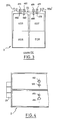
- These gripping members are designated by the references 20a to 20f in the upper part of FIG. 2 , and by the same references assigned the prime symbol in the lower part of this same figure. We recognize on the left of the figures a handle 29.
- the interior of the module is divided longitudinally into two parts. At the level of the section line AA in FIG. 2, six locations of the body of the infrared lure, noted E01 to E06 ( Figure 1). An equal number of lures can be placed in the lower part, and we distinguish the first two of them, E07 and E08, in Figure 3.
- the upper part 200 of the module 2 carries ribs 201, 202, 203 and 204, on which the primary pyrotechnic channels are supported, each having an inlet such as 410 (FIG. 1), a main part such as 411 (FIG. 2) , and an outlet to the interior of the module, such as 412 ( Figure 4).
- these channels will be designated by their intermediate part, whose numerical reference ends in 1.
- Figures 1 to 4 show that one of these primary channels, for example 410 to 412, terminates inside the module on a slightly hollow part, such as 452, and arranged symmetrically with respect to the location.
- module such as E05.
- the other primary pyrotechnic channel of the same pair, such as 461 terminates by a projection inside the module, numbered 462 here, the latter being asymmetrically arranged with respect to the location of the body of the infrared decoy. E05.
- the projections such as 462, and the recesses, such as 452 are intended to produce a tight fitting.
- the decoy body 5 comprises two charges of infrared decoy 51 and 52, placed on either side of an actuating block 6, and connected to the latter by a mechanical connection 53, terminated by bolt heads.
- the lure charges are placed in suitable envelope cups 510 and 520.
- the device 60 comprises a container 601 of charge of ejection 603, provided with a reinforcing primer 602. While burning, the ejection charge 603 must first of all perforate a veil 604, before imparting the required thrust to the assembly constituted by the rest of the block 6 and the two infrared charges 51 and 52. As a variant, the veil 604 is placed in block 6.
- the first pyrotechnic chain (channel 411 for example) continues through a channel 606 drilled in block 6.
- a relay charge 610 is provided, with delay, followed by a primer 611, this assembly being contained in a drawer 61, movable transversely to block 6, under the effect of an elastic return 612.
- this movement takes place in the transverse direction which is oriented not towards the loads 51 and 52, but towards the walls of the module 2.
- the primer 611 has come in line with a veil 630. After drilling of this, the fire is transmitted by channel 631 to the two infrared charges 51 and 52, respectively equipped with the ignition charges 511 and 521.
- the arrival of the drawer 61 in the fire transmission position is subject to several conditions.
- a rod 614 is mounted in abutment, against the elastic return 612, between the slide 61 and an opening made in a wall 615 facing a wall of the launcher box.
- the drawer can therefore only be released after the lure body has left the launcher box.
- the bore 605 communicates with an open transverse bore 623, where a piston 622 provided with an O-ring 621 frictionally slides.
- the piston will only move to the right (FIG. 6) sufficient gas pressure after firing the charge 603 (remember that the ballistics are reversed).
- the piston 622 receives in a radial hole passing through a counterweight 620, which in turn is slidably mounted in a bore 625, parallel to the direction of ejection.
- the counterweight 620 is provided in the middle part with a section restriction 626 between two shoulders, then downwards, with another shoulder, finally followed by a head 627.
- the shoulder 627A placed just before the head 627 abuts on a corresponding shape of the bore 625 formed in the block 6.
- the shoulder 626A is immobilized by a stop of the radial bore 624 of the piston 622.
- the counterweight 620 is therefore blo and the drawer 61 cannot come into the fire transmission position, because the head 627 projects into the bore of this drawer 61.
- the piston 621 moves in abutment to the right. Its radial bore 624 then offers a cross section sufficient for the passage of the counterweight 620.
- the preferred implementation of the invention uses two infrared decoy bodies mounted superimposed in the launcher module 2.
- Block 6 includes a second pyrotechnic channel, which starts with a cell 650, capable of receiving, for example, the projection 422 of the location of the lure body E01 in FIG. 1.
- the fire will then be transmitted by a channel 651, then an elbow 652, and an end of channel 653, the latter ending on the opposite face of the block, vertical to the cell 605 of ejection charge.
- the fire can then be transmitted to a block similar to block 6, and arranged just in below it.
- this lower lure body will have to be actuated beforehand, which will happen under the same conditions as before.
- the lower lure body placed for example in the location E02 of FIG. 1, can be equipped in exactly the same way as that of FIGS. 5 and 6, with a geometry corresponding to that which is illustrated on the figure 1.
- a simple way to do this is to take common blocks 6 and give the infrared charges (51 or 52) a rectangular section close to the square, so that, fixed in one direction, they enter the top location , and that fixed in the perpendicular direction they go in the low location.
- the actuation block of the bodies of lower lures may be simplified, or slightly modified, since it does not require the provision of a second pyrotechnic transmission chain.
- FIGS. 1 to 4 it can be seen that these make it possible to eject in sequence, in a precisely controlled manner, and with very reduced risks for the aircraft, up to 12 bodies of infrared decoy.
- pyrotechnic channels are independently initiated by the pairs of pyrotechnic channels illustrated in FIG. 2. These pyrotechnic channels are in turn initiated by electrical initiators, which are placed in the central corridor of the upper part 202 ( Figure 2), and can be controlled by individual connections from the connector placed at 28, and not shown. The initiators are enclosed under a cover, provided with a flat seal.
- electrical initiators are placed in the central corridor of the upper part 202 ( Figure 2), and can be controlled by individual connections from the connector placed at 28, and not shown.
- the initiators are enclosed under a cover, provided with a flat seal.
- Such initiators are described in the patent application in the name of the applicant entitled “Embedded vehicle launcher module with general reversible safety", filed under under No. 81, whose descriptive content is to be incorporated herein.
- the security bar used in this other patent application is added with advantage to the arrangements according to the present invention.
Landscapes
- Engineering & Computer Science (AREA)
- Aviation & Aerospace Engineering (AREA)
- Radar, Positioning & Navigation (AREA)
- Remote Sensing (AREA)
- General Engineering & Computer Science (AREA)
- Aiming, Guidance, Guns With A Light Source, Armor, Camouflage, And Targets (AREA)
- Radiation-Therapy Devices (AREA)
- Processing Of Solid Wastes (AREA)
- Fire-Detection Mechanisms (AREA)
- Catching Or Destruction (AREA)
- Drying Of Solid Materials (AREA)
- Glass Compositions (AREA)
- Inorganic Insulating Materials (AREA)
- Air Bags (AREA)
- Resistance Heating (AREA)
- Toys (AREA)
- Pretreatment Of Seeds And Plants (AREA)
- Processing And Handling Of Plastics And Other Materials For Molding In General (AREA)
Priority Applications (1)
| Application Number | Priority Date | Filing Date | Title |
|---|---|---|---|
| AT82400860T ATE14927T1 (de) | 1981-06-03 | 1982-05-10 | Vorrichtung mit doppeltem sicherheitssystem zum verteilen von infraroten dueppeln. |
Applications Claiming Priority (2)
| Application Number | Priority Date | Filing Date | Title |
|---|---|---|---|
| FR8110976A FR2507304A1 (fr) | 1981-06-03 | 1981-06-03 | Dispositif lance-leurre infrarouge a mise en oeuvre rapide avec double securite |
| FR8110976 | 1981-06-03 |
Publications (3)
| Publication Number | Publication Date |
|---|---|
| EP0067733A2 true EP0067733A2 (de) | 1982-12-22 |
| EP0067733A3 EP0067733A3 (en) | 1983-02-02 |
| EP0067733B1 EP0067733B1 (de) | 1985-08-14 |
Family
ID=9259141
Family Applications (1)
| Application Number | Title | Priority Date | Filing Date |
|---|---|---|---|
| EP82400860A Expired EP0067733B1 (de) | 1981-06-03 | 1982-05-10 | Vorrichtung mit doppeltem Sicherheitssystem zum Verteilen von infraroten Düppeln |
Country Status (8)
| Country | Link |
|---|---|
| US (1) | US4498392A (de) |
| EP (1) | EP0067733B1 (de) |
| AT (1) | ATE14927T1 (de) |
| DE (1) | DE3265387D1 (de) |
| DK (1) | DK157415C (de) |
| ES (1) | ES8303677A1 (de) |
| FR (1) | FR2507304A1 (de) |
| NO (1) | NO156427C (de) |
Cited By (4)
| Publication number | Priority date | Publication date | Assignee | Title |
|---|---|---|---|---|
| US4682529A (en) * | 1983-12-07 | 1987-07-28 | R. Alkan & Cie | Modular devices for loading cartridges on board aircraft |
| EP0190800A3 (en) * | 1985-02-04 | 1988-07-20 | Philips Norden Ab | Arrangements for dispensing chaff or the like |
| FR2710738A1 (fr) * | 1993-09-28 | 1995-04-07 | Poudres & Explosifs Ste Nale | Dispositif pyrotechnique de sécurité pour la transmission d'une détonation. |
| US6482390B1 (en) | 1995-04-13 | 2002-11-19 | Smithkline Beecham Corporation | Aerosol formulations and method |
Families Citing this family (16)
| Publication number | Priority date | Publication date | Assignee | Title |
|---|---|---|---|---|
| US4791870A (en) * | 1983-04-05 | 1988-12-20 | Haley & Weller Limited | Pyrotechnic assembly |
| DE3421708A1 (de) * | 1984-06-12 | 1985-12-12 | Buck Chemisch-Technische Werke GmbH & Co, 7347 Bad Überkingen | Einrichtung zur erzeugung einer scheinzielwolke, insbesondere einer infrarot-scheinzielwolke |
| DE3515166A1 (de) * | 1985-04-26 | 1986-10-30 | Buck Chemisch-Technische Werke GmbH & Co, 7347 Bad Überkingen | Wurfkoerper zur darstellung eines infrarot-flaechenstrahlers |
| US5074216A (en) * | 1987-09-03 | 1991-12-24 | Loral Corporation | Infrared signature enhancement decoy |
| US5456455A (en) * | 1994-02-01 | 1995-10-10 | Thiokol Corporation | Flare pellet and process for making same |
| US5561259A (en) * | 1994-10-13 | 1996-10-01 | Alliant Techsystems Inc. | Decoy flare with sequencer ignition |
| US5750918A (en) * | 1995-10-17 | 1998-05-12 | Foster-Miller, Inc. | Ballistically deployed restraining net |
| US5895882A (en) * | 1997-12-08 | 1999-04-20 | The United States Of America As Represented By The Secretary Of The Navy | Air-delivered remotely-activated infrared anti-ship missile decoy and deployment method |
| US6055909A (en) | 1998-09-28 | 2000-05-02 | Raytheon Company | Electronically configurable towed decoy for dispensing infrared emitting flares |
| DE10061748C1 (de) * | 2000-12-12 | 2002-06-13 | Dornier Gmbh | Schleppkörper zur Flugzieldarstellung |
| US6662700B2 (en) * | 2002-05-03 | 2003-12-16 | Raytheon Company | Method for protecting an aircraft against a threat that utilizes an infrared sensor |
| US7028947B2 (en) * | 2004-04-30 | 2006-04-18 | Mlho, Inc. | Self-powered tethered decoy for heat-seeking transport aircraft missile defense |
| US20110285088A1 (en) * | 2010-05-19 | 2011-11-24 | GREGG Richard | Pyrotechnic cassette |
| FR2991666B1 (fr) * | 2012-06-07 | 2015-02-27 | Mbda France | Procede, dispositif et systeme de leurrage pour la protection d'un aeronef |
| GB2601782B (en) * | 2020-12-10 | 2024-09-11 | Bae Systems Plc | Countermeasure device |
| EP4544261A1 (de) * | 2022-06-22 | 2025-04-30 | Orica International Pte Ltd | Systeme und verfahren/prozesse |
Family Cites Families (10)
| Publication number | Priority date | Publication date | Assignee | Title |
|---|---|---|---|---|
| US2459687A (en) * | 1937-06-22 | 1949-01-18 | Josef B Decker | Aerial signal |
| US2476117A (en) * | 1944-10-21 | 1949-07-12 | Short Frank | Antimine bomb |
| US3841219A (en) * | 1964-08-12 | 1974-10-15 | Gen Dynamics Corp | Decoy rounds for counter measures system |
| US3511457A (en) * | 1968-09-06 | 1970-05-12 | All American Eng Co | Aerial cargo dispenser |
| FR2036520A5 (de) * | 1969-03-24 | 1970-12-24 | Thomson Csf | |
| US3724385A (en) * | 1971-09-20 | 1973-04-03 | Us Navy | Fuze having a pneumatic and inertia arming system |
| GB1534134A (en) * | 1975-12-12 | 1978-11-29 | Lacroix Soc E | Lure launching cartridges |
| US4171669A (en) * | 1978-02-13 | 1979-10-23 | The United States Of America As Represented By The Secretary Of The Navy | Decoy flare |
| US4266462A (en) * | 1979-01-22 | 1981-05-12 | Western Gear Corporation | Airborne stores arming trigger unit |
| FR2490333B1 (fr) * | 1980-09-12 | 1986-05-02 | Lacroix E Tous Artifices | Cartouche a actionnement pyrotechnique de charge utile avec securite |
-
1981
- 1981-06-03 FR FR8110976A patent/FR2507304A1/fr active Granted
-
1982
- 1982-05-10 DE DE8282400860T patent/DE3265387D1/de not_active Expired
- 1982-05-10 EP EP82400860A patent/EP0067733B1/de not_active Expired
- 1982-05-10 AT AT82400860T patent/ATE14927T1/de not_active IP Right Cessation
- 1982-05-25 DK DK236282A patent/DK157415C/da not_active IP Right Cessation
- 1982-05-25 ES ES512505A patent/ES8303677A1/es not_active Expired
- 1982-05-25 NO NO821723A patent/NO156427C/no unknown
- 1982-06-01 US US06/384,098 patent/US4498392A/en not_active Expired - Lifetime
Cited By (4)
| Publication number | Priority date | Publication date | Assignee | Title |
|---|---|---|---|---|
| US4682529A (en) * | 1983-12-07 | 1987-07-28 | R. Alkan & Cie | Modular devices for loading cartridges on board aircraft |
| EP0190800A3 (en) * | 1985-02-04 | 1988-07-20 | Philips Norden Ab | Arrangements for dispensing chaff or the like |
| FR2710738A1 (fr) * | 1993-09-28 | 1995-04-07 | Poudres & Explosifs Ste Nale | Dispositif pyrotechnique de sécurité pour la transmission d'une détonation. |
| US6482390B1 (en) | 1995-04-13 | 2002-11-19 | Smithkline Beecham Corporation | Aerosol formulations and method |
Also Published As
| Publication number | Publication date |
|---|---|
| EP0067733B1 (de) | 1985-08-14 |
| DK157415B (da) | 1990-01-02 |
| FR2507304A1 (fr) | 1982-12-10 |
| NO156427B (no) | 1987-06-09 |
| NO821723L (no) | 1982-12-06 |
| ATE14927T1 (de) | 1985-08-15 |
| ES512505A0 (es) | 1983-03-01 |
| DK157415C (da) | 1990-05-28 |
| EP0067733A3 (en) | 1983-02-02 |
| ES8303677A1 (es) | 1983-03-01 |
| NO156427C (no) | 1987-09-16 |
| DK236282A (da) | 1983-02-10 |
| US4498392A (en) | 1985-02-12 |
| DE3265387D1 (en) | 1985-09-19 |
| FR2507304B1 (de) | 1984-12-07 |
Similar Documents
| Publication | Publication Date | Title |
|---|---|---|
| EP0067733A2 (de) | Vorrichtung mit doppeltem Sicherheitssystem zum Verteilen von infraroten Düppeln | |
| EP0048204B1 (de) | Patrone mit pyrotechnisch betätigter Nutzladung und mit Sicherheitseinrichtungen | |
| EP0389358B1 (de) | Leitwerkausspreizungssystem für ein Geschoss | |
| EP0324688B1 (de) | Von der Schulter abzufeuernder Raketenwerfer | |
| EP0067731A2 (de) | Vorrichtung zum Befestigen von einem am Flugzeug angeordneten Element, insbesondere von einer Leuchtkörperabschusseinrichtung | |
| CA2912652C (fr) | Generateur de gaz pyrotechnique pour actionner un verin | |
| CA2220892C (fr) | Systeme d'obturation pour un orifice d'entree d'air dans la chambre de combustion d'un statoreacteur | |
| EP0072261B1 (de) | Vorrichtung zum Verteilen elektromagnetischer Düppel, insbesondere für Flugzeuge | |
| EP3325795B1 (de) | Vorrichtung zur abänderung eines gasausstossabschnitts | |
| FR2724907A1 (fr) | Lanceur de leurres electromagnetiques a ejection differee | |
| EP1714105B1 (de) | Gesicherte vorrichtung zur zuführung und zündung von patronen wie zum beispiel scheinpatronen | |
| FR2729749A1 (fr) | Cartouche de leurrage infrarouge et dispositif de leurrage comportant une telle cartouche | |
| FR2559069A1 (fr) | Dispositif et procede de securite contre les incendies et les explosions pour le stockage des matieres combustibles ou explosives | |
| EP0597750B1 (de) | Gerät zum Halten und Auswerfen eines Objekts bezüglich eines Trägers, mit einer kontrollierten Ablauffolge | |
| EP0230196B1 (de) | Geschoss mit pyrotechnischer Ladung | |
| FR2649194A1 (fr) | Dispositif d'ejection pour munition amphibie et propulseur independant en faisant partie | |
| EP2029956B1 (de) | Sicherheitszünder für pyrotechnische vorrichtung | |
| WO2005098346A1 (fr) | Dispositif emetteur de rayonnement notamment infrarouge | |
| FR2519784A1 (fr) | Dispositif de transmission multivoies d'un ordre pyrotechnique comportant un ensemble relais a relevement de pieces | |
| EP0233431B1 (de) | Patrone mit einem eine pyrotechnische Ladung tragenden Geschosskörper | |
| FR2530332A1 (fr) | Dispositif d'ouverture de l'empennage d'un projectile | |
| FR2652644A2 (en) | Device for unconfining a military charge containing an explosive | |
| EP2769168B1 (de) | Gasgenerator mit einer sicherheitsvorrichtung für langsame erhitzung | |
| EP2153162B1 (de) | Pyrotechnische kette zur zündung einer hauptantriebsladung für eine rakete | |
| WO2003040645A1 (fr) | Engin explosif a plusieurs elements unitaires |
Legal Events
| Date | Code | Title | Description |
|---|---|---|---|
| PUAI | Public reference made under article 153(3) epc to a published international application that has entered the european phase |
Free format text: ORIGINAL CODE: 0009012 |
|
| PUAL | Search report despatched |
Free format text: ORIGINAL CODE: 0009013 |
|
| AK | Designated contracting states |
Designated state(s): AT BE CH DE FR GB IT LI LU NL SE |
|
| AK | Designated contracting states |
Designated state(s): AT BE CH DE FR GB IT LI LU NL SE |
|
| 17P | Request for examination filed |
Effective date: 19830422 |
|
| ITF | It: translation for a ep patent filed | ||
| GRAA | (expected) grant |
Free format text: ORIGINAL CODE: 0009210 |
|
| AK | Designated contracting states |
Designated state(s): AT BE CH DE FR GB IT LI LU NL SE |
|
| REF | Corresponds to: |
Ref document number: 14927 Country of ref document: AT Date of ref document: 19850815 Kind code of ref document: T |
|
| REF | Corresponds to: |
Ref document number: 3265387 Country of ref document: DE Date of ref document: 19850919 |
|
| BECN | Be: change of holder's name |
Effective date: 19850814 |
|
| RAP2 | Party data changed (patent owner data changed or rights of a patent transferred) |
Owner name: ETIENNE LACROIX - TOUS ARTIFICES SA |
|
| PLBE | No opposition filed within time limit |
Free format text: ORIGINAL CODE: 0009261 |
|
| STAA | Information on the status of an ep patent application or granted ep patent |
Free format text: STATUS: NO OPPOSITION FILED WITHIN TIME LIMIT |
|
| 26N | No opposition filed | ||
| NLT2 | Nl: modifications (of names), taken from the european patent patent bulletin |
Owner name: ETIENNE LACROIX - TOUS ARTIFICES S.A. TE MURET, FR |
|
| ITTA | It: last paid annual fee | ||
| EPTA | Lu: last paid annual fee | ||
| EAL | Se: european patent in force in sweden |
Ref document number: 82400860.1 |
|
| PGFP | Annual fee paid to national office [announced via postgrant information from national office to epo] |
Ref country code: CH Payment date: 19950517 Year of fee payment: 14 |
|
| PGFP | Annual fee paid to national office [announced via postgrant information from national office to epo] |
Ref country code: AT Payment date: 19950526 Year of fee payment: 14 |
|
| PGFP | Annual fee paid to national office [announced via postgrant information from national office to epo] |
Ref country code: NL Payment date: 19950531 Year of fee payment: 14 |
|
| PGFP | Annual fee paid to national office [announced via postgrant information from national office to epo] |
Ref country code: LU Payment date: 19950701 Year of fee payment: 14 |
|
| PG25 | Lapsed in a contracting state [announced via postgrant information from national office to epo] |
Ref country code: LU Free format text: LAPSE BECAUSE OF NON-PAYMENT OF DUE FEES Effective date: 19960510 Ref country code: AT Effective date: 19960510 |
|
| PG25 | Lapsed in a contracting state [announced via postgrant information from national office to epo] |
Ref country code: LI Effective date: 19960531 Ref country code: CH Effective date: 19960531 |
|
| PG25 | Lapsed in a contracting state [announced via postgrant information from national office to epo] |
Ref country code: NL Effective date: 19961201 |
|
| REG | Reference to a national code |
Ref country code: CH Ref legal event code: PL |
|
| NLV4 | Nl: lapsed or anulled due to non-payment of the annual fee |
Effective date: 19961201 |
|
| PGFP | Annual fee paid to national office [announced via postgrant information from national office to epo] |
Ref country code: FR Payment date: 19990429 Year of fee payment: 18 |
|
| PGFP | Annual fee paid to national office [announced via postgrant information from national office to epo] |
Ref country code: GB Payment date: 19990504 Year of fee payment: 18 |
|
| PGFP | Annual fee paid to national office [announced via postgrant information from national office to epo] |
Ref country code: SE Payment date: 19990512 Year of fee payment: 18 |
|
| PGFP | Annual fee paid to national office [announced via postgrant information from national office to epo] |
Ref country code: DE Payment date: 19990514 Year of fee payment: 18 |
|
| PGFP | Annual fee paid to national office [announced via postgrant information from national office to epo] |
Ref country code: BE Payment date: 19990611 Year of fee payment: 18 |
|
| PG25 | Lapsed in a contracting state [announced via postgrant information from national office to epo] |
Ref country code: GB Free format text: LAPSE BECAUSE OF NON-PAYMENT OF DUE FEES Effective date: 20000510 |
|
| PG25 | Lapsed in a contracting state [announced via postgrant information from national office to epo] |
Ref country code: SE Free format text: LAPSE BECAUSE OF NON-PAYMENT OF DUE FEES Effective date: 20000511 |
|
| PG25 | Lapsed in a contracting state [announced via postgrant information from national office to epo] |
Ref country code: BE Free format text: LAPSE BECAUSE OF NON-PAYMENT OF DUE FEES Effective date: 20000531 |
|
| BERE | Be: lapsed |
Owner name: ETIENNE LACROIX - TOUS ARTIFICES S.A. Effective date: 20000531 |
|
| GBPC | Gb: european patent ceased through non-payment of renewal fee |
Effective date: 20000510 |
|
| EUG | Se: european patent has lapsed |
Ref document number: 82400860.1 |
|
| PG25 | Lapsed in a contracting state [announced via postgrant information from national office to epo] |
Ref country code: FR Free format text: LAPSE BECAUSE OF NON-PAYMENT OF DUE FEES Effective date: 20010131 |
|
| PG25 | Lapsed in a contracting state [announced via postgrant information from national office to epo] |
Ref country code: DE Free format text: LAPSE BECAUSE OF NON-PAYMENT OF DUE FEES Effective date: 20010301 |
|
| REG | Reference to a national code |
Ref country code: FR Ref legal event code: ST |