EP0067923A1 - Installation de freinage pour trains routiers - Google Patents
Installation de freinage pour trains routiers Download PDFInfo
- Publication number
- EP0067923A1 EP0067923A1 EP82100792A EP82100792A EP0067923A1 EP 0067923 A1 EP0067923 A1 EP 0067923A1 EP 82100792 A EP82100792 A EP 82100792A EP 82100792 A EP82100792 A EP 82100792A EP 0067923 A1 EP0067923 A1 EP 0067923A1
- Authority
- EP
- European Patent Office
- Prior art keywords
- trailer
- brake
- valve
- braking device
- solenoid valve
- Prior art date
- Legal status (The legal status is an assumption and is not a legal conclusion. Google has not performed a legal analysis and makes no representation as to the accuracy of the status listed.)
- Granted
Links
- 238000009434 installation Methods 0.000 title 1
- 230000008878 coupling Effects 0.000 claims abstract description 10
- 238000010168 coupling process Methods 0.000 claims abstract description 10
- 238000005859 coupling reaction Methods 0.000 claims abstract description 10
- 230000001419 dependent effect Effects 0.000 claims description 5
- 238000009530 blood pressure measurement Methods 0.000 abstract 1
- 230000004048 modification Effects 0.000 description 3
- 238000012986 modification Methods 0.000 description 3
- 238000010276 construction Methods 0.000 description 1
- 239000000725 suspension Substances 0.000 description 1
- 230000001360 synchronised effect Effects 0.000 description 1
- 238000009423 ventilation Methods 0.000 description 1
Images


Classifications
-
- B—PERFORMING OPERATIONS; TRANSPORTING
- B60—VEHICLES IN GENERAL
- B60T—VEHICLE BRAKE CONTROL SYSTEMS OR PARTS THEREOF; BRAKE CONTROL SYSTEMS OR PARTS THEREOF, IN GENERAL; ARRANGEMENT OF BRAKING ELEMENTS ON VEHICLES IN GENERAL; PORTABLE DEVICES FOR PREVENTING UNWANTED MOVEMENT OF VEHICLES; VEHICLE MODIFICATIONS TO FACILITATE COOLING OF BRAKES
- B60T17/00—Component parts, details, or accessories of power brake systems not covered by groups B60T8/00, B60T13/00 or B60T15/00, or presenting other characteristic features
- B60T17/18—Safety devices; Monitoring
-
- B—PERFORMING OPERATIONS; TRANSPORTING
- B60—VEHICLES IN GENERAL
- B60T—VEHICLE BRAKE CONTROL SYSTEMS OR PARTS THEREOF; BRAKE CONTROL SYSTEMS OR PARTS THEREOF, IN GENERAL; ARRANGEMENT OF BRAKING ELEMENTS ON VEHICLES IN GENERAL; PORTABLE DEVICES FOR PREVENTING UNWANTED MOVEMENT OF VEHICLES; VEHICLE MODIFICATIONS TO FACILITATE COOLING OF BRAKES
- B60T13/00—Transmitting braking action from initiating means to ultimate brake actuator with power assistance or drive; Brake systems incorporating such transmitting means, e.g. air-pressure brake systems
- B60T13/10—Transmitting braking action from initiating means to ultimate brake actuator with power assistance or drive; Brake systems incorporating such transmitting means, e.g. air-pressure brake systems with fluid assistance, drive, or release
- B60T13/66—Electrical control in fluid-pressure brake systems
- B60T13/68—Electrical control in fluid-pressure brake systems by electrically-controlled valves
- B60T13/683—Electrical control in fluid-pressure brake systems by electrically-controlled valves in pneumatic systems or parts thereof
Definitions
- the invention relates to a train brake system according to the preamble of the main claim.
- Such a train brake system is known (CH-PS 32 60 46).
- This known brake system solves the problem of exhaustion in single-line brake systems that were customary in the past.
- the problem of coordinating the use of towing vehicles and suspension brakes cannot be solved with such a brake system.
- the wagon train brake system with the characterizing features of the main claim has the advantage that a very precise coordination of the use of the wagon and trailer brake is possible with a few additional components. According to a further feature of the invention it is also advantageous that a modulated signal can be sent to the hanger brake via the stop light line, which is necessary anyway.
- a modulator on the trailer can be integrated into an electronic control device of an anti-lock device.
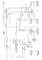
- FIG. 1 shows a wagon train brake system
- FIG. 2 shows a detail according to FIG. 1
- FIG. 3 shows a modification of the embodiment according to FIG. 2
- FIGS. 4 to 6 show further modifications of the embodiment according to FIG. 2
- FIG. 7 shows another wagon train brake system.
- a compressed air wagon train brake system is provided in part on a wagon 1 and in part on a trailer 2.
- Essential parts of the brake system on the tractor 1 are a compressor 3, two reservoirs 4 and 5, a dual-circuit brake valve 6, four brake cylinders 7, 8, 9, 10 and a trailer control valve 11 and two coupling heads 12 and 13, one for one Brake line 14 and one for a supply line 15.
- a pressure sensor 16 and 17 is provided for each brake circuit on the output side of the dual-circuit brake valve 6. which are connected to an electronic control unit 18. Of these, three electrical lines 19, 20 and 21 lead to an electrical line coupling head 22 at the end of the towing vehicle 1.
- the trailer 2 has a supply line coupling head 23, a brake line coupling head 24 and an electric line coupling head 25, furthermore a trailer brake valve 26, a storage container 27, a relay valve as a load-dependent brake force regulator 28, and four brake cylinders 29, 30, 31 and 32.
- a control connection 33 of the brake force regulator 28 is connected to a two-way valve 34 which is connected on one side to a line 35 from the trailer brake valve 26 and on the other side to a control line 36 which is brought up from the reservoir 27.
- a solenoid valve device 37 which consists of two solenoid valves 38 and 39 in FIG.
- the solenoid valve device 37 can be designed differently, it can, as FIG. 2 shows, consist of a 2/2 and a 3/2-way solenoid valve arranged directly behind it, it can have the two-way valve 34 integrated (FIG. 3) can consist of two 3/2-way solenoid valves (Figure 4), it can be constructed as a 3/2-way solenoid valve with a 2/2-way solenoid valve immediately behind it ( Figure 5) or it is simply in the simplest way designed as a 2/2 Weje solenoid valve ( Figure 6), but then a throttle 40 should be provided in line 35.
- a pressure sensor 41 is connected to the control connection 33 of the load-dependent brake force regulator 28 and is connected to the coupling head 25 via an electrical line 42.
- one or the two solenoid valves 38 and 39 each have an electrical line 43 or 44 connected to the coupling head 25.
- the pressure controlled by the dual-circuit brake valve 6 gives a signal to the electronic control unit 18 via the two pressure transducers 16 and 17. Since the brake valve pressure has not yet reached the trailer 2 at the same time, pressure from the trailer via line 42 becomes pressure Reported "zero".
- the electronic control unit 18 then gives an electrical signal to the solenoid valve device 37 on the trailer 2, which give control pressure from the trailer reservoir 27 to the control connection 33 of the brake force regulator 28.
- the brake force regulator 28 controls the brake pressure on the trailer brake cylinders 29 to 32. In this way, the trailer 2 is already electronically braked before the brake pressure from the towing vehicle 1 is applied to the load-dependent brake force regulator 28 via the trailer control valve 11.
- the solenoid valve device 37 is constructed in a similar way to the solenoid valve device of an anti-lock device, that is, with the corresponding design according to FIGS.
- control during pressure increase and pressure drop is possible.
- the designs according to Figures 5 to 6 leave a controller only in the pressure rise phase, ie when the brake pressure builds up, because ventilation is carried out in line 35 here.
- the one-valve design according to FIG. 6 it is possible to work with only one solenoid valve by deliberately flowing control connection 33 into line 35.
- the design according to FIG. 2 only allows the control connection 33 to be vented via the solenoid valve device 37 if the trailer brake valve pressure applied to the two-way valve 34 is still low.
- the electronic control unit 18 can also be arranged on the trailer 2.
- FIG. 7 shows a modification of the embodiment according to FIG. 1; corresponding parts therefore have the same reference numbers.
- a stop light line 45 with stop light 50 on the trailer 2 which runs anyway between the towing vehicle 1 and trailer 2, is used to transmit an additional signal between the two vehicles 1 and 2.
- an electronic control unit 46 with a modulator 47 is provided on the towing vehicle 1 and an electronic control unit 48 with a demodulator U9 on the trailer 2.
- the throttle 40 of the embodiment according to FIG. 6 is replaced by a throttle check valve 51.
- the largest pressure rise signal is forwarded in each case in the electronic control unit 46 of the towing vehicle.
- the stop light current is impressed on an identifier of the determined pressure level, which can be carried out, for example, frequency modulated.
- the stop light 50 on the trailer 2 is illuminated via the stop light line 45.
- the modulated portion of the stop light current is further processed in the electronic control unit 48 of the trailer, i.e. demodulated in demodulator 49.
- a yes / no control of the solenoid valve device 37 is derived by comparison with the pressure signal at the load-dependent brake force controller 28.
- the brake pressure is continuously measured at the outlet thereof.
- the passage through the solenoid valve device 37 is opened if the brake pressure has not yet reached the trailer 2 via the trailer control valve 11 through the air line connection. If a synchronous or a predetermined pressure difference between the towing vehicle and the trailer is reached, the solenoid valve device switches off again. The direct pneumatic control remains unaffected by the electronic control.
- Any vehicle combination can be operated with the device according to the invention.
- E.g. vehicles with changing equipment (with or without electronically controlled advance) can be coupled.
- the brake light 50 is actuated in any case, even if the trailer 2 is not provided with the device according to the invention.
- the towing vehicle 1 is not provided with the device according to the invention but the trailer 2, a magnetic valve which is possibly arranged on the trailer 2 is not actuated by the missing identifier. If there is no such identification, the solenoid valve can replacement design can be controlled for a short time, possibly also clocked in order to simulate an advance. However, this is only possible for small pressure ranges, e.g. brake systems, since the level of pressure control on the towing vehicle 1 on the electrical control side is unknown. A compensation with the actuation pressure from the towing vehicle 1 is given in any case.
Landscapes
- Engineering & Computer Science (AREA)
- Transportation (AREA)
- Mechanical Engineering (AREA)
- Regulating Braking Force (AREA)
Applications Claiming Priority (2)
| Application Number | Priority Date | Filing Date | Title |
|---|---|---|---|
| DE3124480 | 1981-06-23 | ||
| DE19813124480 DE3124480A1 (de) | 1981-06-23 | 1981-06-23 | "wagenzugbremseinrichtung" |
Publications (2)
| Publication Number | Publication Date |
|---|---|
| EP0067923A1 true EP0067923A1 (fr) | 1982-12-29 |
| EP0067923B1 EP0067923B1 (fr) | 1986-05-14 |
Family
ID=6135108
Family Applications (1)
| Application Number | Title | Priority Date | Filing Date |
|---|---|---|---|
| EP82100792A Expired EP0067923B1 (fr) | 1981-06-23 | 1982-02-04 | Installation de freinage pour trains routiers |
Country Status (2)
| Country | Link |
|---|---|
| EP (1) | EP0067923B1 (fr) |
| DE (2) | DE3124480A1 (fr) |
Cited By (4)
| Publication number | Priority date | Publication date | Assignee | Title |
|---|---|---|---|---|
| GB2131508A (en) * | 1982-12-08 | 1984-06-20 | Saab Scania Ab | Braking system for a trailer |
| EP0120143A1 (fr) * | 1983-02-23 | 1984-10-03 | Rockwell International Corporation | Système de freinage pour remorques |
| US4585278A (en) * | 1983-12-24 | 1986-04-29 | Robert Bosch Gmbh | Brake system for vehicle combinations |
| EP0586203A3 (fr) * | 1992-09-03 | 1994-10-19 | Grau Ltd | Systèmes de freinage. |
Families Citing this family (2)
| Publication number | Priority date | Publication date | Assignee | Title |
|---|---|---|---|---|
| DE3703639A1 (de) * | 1987-02-06 | 1988-08-18 | Bosch Gmbh Robert | Elektro-pneumatische bremsanlage fuer zugfahrzeuge |
| DE3936726A1 (de) * | 1989-11-04 | 1991-05-08 | Wabco Westinghouse Fahrzeug | Verfahren zur abbremsung eines mit druckbetaetigten bremsen ausgeruesteten fahrzeugzuges |
Citations (4)
| Publication number | Priority date | Publication date | Assignee | Title |
|---|---|---|---|---|
| US3768870A (en) * | 1972-03-15 | 1973-10-30 | D Howard | Electrically actuated trailer brake control system |
| DE2420665B2 (de) * | 1974-04-29 | 1976-10-28 | Cermak, Eduard, Dipl.-Ing., 7100 Heilbronn | Elektropneumatische bremssteuereinrichtung fuer fahrzeugzuege |
| US4072362A (en) * | 1976-06-14 | 1978-02-07 | Lambert Brake Corporation | Trailer brake system |
| US4109968A (en) * | 1977-07-28 | 1978-08-29 | Rollin L. Wood | Tractor-trailer brake system with improved means for assuring application of trailer brakes concomitantly with tractor brakes |
Family Cites Families (3)
| Publication number | Priority date | Publication date | Assignee | Title |
|---|---|---|---|---|
| CH326046A (de) * | 1954-01-20 | 1957-11-30 | Westinghouse Bremsen Ges Mbh | Ein-Leitungs-Bremse an Anhängern von Lastzügen |
| US3232674A (en) * | 1963-02-13 | 1966-02-01 | Kelsey Hayes Co | Tractor trailer brake system |
| FR2133591B1 (fr) * | 1971-04-16 | 1977-06-17 | Bendix Corp |
-
1981
- 1981-06-23 DE DE19813124480 patent/DE3124480A1/de not_active Ceased
-
1982
- 1982-02-04 EP EP82100792A patent/EP0067923B1/fr not_active Expired
- 1982-02-04 DE DE8282100792T patent/DE3271089D1/de not_active Expired
Patent Citations (4)
| Publication number | Priority date | Publication date | Assignee | Title |
|---|---|---|---|---|
| US3768870A (en) * | 1972-03-15 | 1973-10-30 | D Howard | Electrically actuated trailer brake control system |
| DE2420665B2 (de) * | 1974-04-29 | 1976-10-28 | Cermak, Eduard, Dipl.-Ing., 7100 Heilbronn | Elektropneumatische bremssteuereinrichtung fuer fahrzeugzuege |
| US4072362A (en) * | 1976-06-14 | 1978-02-07 | Lambert Brake Corporation | Trailer brake system |
| US4109968A (en) * | 1977-07-28 | 1978-08-29 | Rollin L. Wood | Tractor-trailer brake system with improved means for assuring application of trailer brakes concomitantly with tractor brakes |
Cited By (5)
| Publication number | Priority date | Publication date | Assignee | Title |
|---|---|---|---|---|
| GB2131508A (en) * | 1982-12-08 | 1984-06-20 | Saab Scania Ab | Braking system for a trailer |
| EP0120143A1 (fr) * | 1983-02-23 | 1984-10-03 | Rockwell International Corporation | Système de freinage pour remorques |
| US4585278A (en) * | 1983-12-24 | 1986-04-29 | Robert Bosch Gmbh | Brake system for vehicle combinations |
| EP0586203A3 (fr) * | 1992-09-03 | 1994-10-19 | Grau Ltd | Systèmes de freinage. |
| US5549362A (en) * | 1992-09-03 | 1996-08-27 | Grau Limited | Braking systems |
Also Published As
| Publication number | Publication date |
|---|---|
| DE3124480A1 (de) | 1983-01-05 |
| EP0067923B1 (fr) | 1986-05-14 |
| DE3271089D1 (en) | 1986-06-19 |
Similar Documents
| Publication | Publication Date | Title |
|---|---|---|
| DE4227084B4 (de) | Druckregelmodul einer Druckluft-Fahrzeugbremsanlage | |
| DE3219140C2 (de) | Wagenzug-Bremsanlage | |
| DE3230970C2 (fr) | ||
| EP0146769B1 (fr) | Installation de freinage pour trains routiers | |
| DE19581733B4 (de) | Bremssteueranordnung für einen Fahrzeugverbund | |
| DE3514949A1 (de) | Druckmittel-bremsanlage fuer den anhaenger eines fahrzeuges | |
| DE4016463A1 (de) | Bremsanlage mit wenigstens einem bremskreis | |
| DE3501179A1 (de) | Elektrische bremsanlage | |
| DE3207793A1 (de) | Wagenzugbremsanlage | |
| DE1910987A1 (de) | Vorrichtung zur Anzeige von AEnderungen der Winkelgeschwindigkeit und Fahrzeugbremssystem mit einem derartigen Anzeigegeraet | |
| DE102018123750A1 (de) | Elektropneumatische Anhängersteuerventileinheit für Nordamerika | |
| WO1995016594A1 (fr) | Systeme de freinage electropneumatique pour vehicules automobiles | |
| DE102015119135A1 (de) | Pneumatische Bremseinrichtung | |
| EP3840992A1 (fr) | Arrangement de frein de stationnement électropneumatique avec vanne d'arrêt et procédé de commande d'un système de freinage pneumatique à commande électronique | |
| DE3149110A1 (de) | Elektro-druckmittel-bremsanlage | |
| DE2655951A1 (de) | Bremsblockierschutzeinrichtung | |
| EP0250738A2 (fr) | Installation électrique de freinage à fluide sous pression | |
| DE19907667C1 (de) | Vorrichtung zur Befestigung von pneumatischen und/oder elektropneumatischen Einrichtungen eines Fahrzeugs | |
| EP0345203A2 (fr) | Installation de freinage avec moyen de pression régulé électroniquement | |
| EP0067923B1 (fr) | Installation de freinage pour trains routiers | |
| DE3545021A1 (de) | Elektro-pneumatische bremsanlage | |
| DE3239970A1 (de) | Wagenzug-bremsanlage | |
| EP0205928A1 (fr) | Dispositif de circuit pour détection d'une rupture de conduite dans un système électro-pneumatique de freinage de véhicule équipé d'un frein de remorque commandé à partir du tracteur | |
| EP0404780B1 (fr) | Systeme de reglage antiblocage | |
| DE3628681A1 (de) | Luftfederung fuer fahrzeug mit doppelachse |
Legal Events
| Date | Code | Title | Description |
|---|---|---|---|
| PUAI | Public reference made under article 153(3) epc to a published international application that has entered the european phase |
Free format text: ORIGINAL CODE: 0009012 |
|
| 17P | Request for examination filed |
Effective date: 19820204 |
|
| AK | Designated contracting states |
Designated state(s): DE FR GB IT NL SE |
|
| ITF | It: translation for a ep patent filed | ||
| GRAA | (expected) grant |
Free format text: ORIGINAL CODE: 0009210 |
|
| AK | Designated contracting states |
Kind code of ref document: B1 Designated state(s): DE FR GB IT NL SE |
|
| REF | Corresponds to: |
Ref document number: 3271089 Country of ref document: DE Date of ref document: 19860619 |
|
| ET | Fr: translation filed | ||
| PLBI | Opposition filed |
Free format text: ORIGINAL CODE: 0009260 |
|
| 26 | Opposition filed |
Opponent name: WABCO WESTINGHOUSE FAHRZEUGBREMSEN GMBH Effective date: 19861216 |
|
| NLR1 | Nl: opposition has been filed with the epo |
Opponent name: WABCO WESTINGHOUSE FAHRZEUGBREMSEN GMBH |
|
| PGFP | Annual fee paid to national office [announced via postgrant information from national office to epo] |
Ref country code: FR Payment date: 19890227 Year of fee payment: 8 |
|
| ITTA | It: last paid annual fee | ||
| PGFP | Annual fee paid to national office [announced via postgrant information from national office to epo] |
Ref country code: SE Payment date: 19890228 Year of fee payment: 8 Ref country code: NL Payment date: 19890228 Year of fee payment: 8 Ref country code: GB Payment date: 19890228 Year of fee payment: 8 |
|
| PGFP | Annual fee paid to national office [announced via postgrant information from national office to epo] |
Ref country code: DE Payment date: 19890426 Year of fee payment: 8 |
|
| RDAG | Patent revoked |
Free format text: ORIGINAL CODE: 0009271 |
|
| STAA | Information on the status of an ep patent application or granted ep patent |
Free format text: STATUS: PATENT REVOKED |
|
| 27W | Patent revoked |
Effective date: 19890819 |
|
| GBPR | Gb: patent revoked under art. 102 of the ep convention designating the uk as contracting state | ||
| NLR2 | Nl: decision of opposition | ||
| EUG | Se: european patent has lapsed |
Ref document number: 82100792.9 Effective date: 19900110 |